4WD OPEL FRONTERA 1998 Workshop Manual
[x] Cancel search | Manufacturer: OPEL, Model Year: 1998, Model line: FRONTERA, Model: OPEL FRONTERA 1998Pages: 6000, PDF Size: 97 MB
Page 534 of 6000
4B1–1 DRIVE LINE CONTROL SYSTEM (SHIFT ON THE FLY)
DRIVELINE/AXLE
DRIVELINE CONTROL SYSTEM (SHIFT ON THE FLY)
CONTENTS
Service Precaution 4B1–1. . . . . . . . . . . . . . . . . . . . . .
Shift on the Fly System (Lever Type) 4B1–2. . . . . . .
Outline of Shift on the Fly System
(Lever Type) 4B1–2. . . . . . . . . . . . . . . . . . . . . . . . . . .
Shift on the Fly Vacuum Piping and Electric
Equipment (For Lever Control Type) 4B1–3. . . . . .
Vacuum Piping Diagram 4B1–3. . . . . . . . . . . . . . . .
Inspection and Repair 4B1–4. . . . . . . . . . . . . . . . . .
Shift on the Fly System (Push Button Type) 4B1–7.
Outline of Shift on the Fly System
(Push Button Type) 4B1–7. . . . . . . . . . . . . . . . . . . . Functions of Indicator Lamp 4B1–11. . . . . . . . . . . . . . .
Diagnosis 4B1–11. . . . . . . . . . . . . . . . . . . . . . . . . . . . .
Front Axle Diagnosis 4B1–30. . . . . . . . . . . . . . . . . . .
Shift on the Fly Vacuum Piping and Electric
Equipment (For Push Button Type) 4B1–32. . . . . . . .
Vacuum Piping Diagram 4B1–32. . . . . . . . . . . . . . . .
Inspection and Repair 4B1–33. . . . . . . . . . . . . . . . . .
4WD Control Unit (For Push Button Type) 4B1–36. .
4WD Control Unit Associated Parts 4B1–36. . . . . .
Removal 4B1–37. . . . . . . . . . . . . . . . . . . . . . . . . . . . .
Installation 4B1–37. . . . . . . . . . . . . . . . . . . . . . . . . . . .
Service Precaution
WARNING: IF SO EQUIPPED WITH A
SUPPLEMENTAL RESTRAINT SYSTEM (SRS),
REFER TO THE SRS COMPONENT AND WIRING
LOCATION VIEW IN ORDER TO DETERMINE
WHETHER YOU ARE PERFORMING SERVICE ON OR
NEAR THE SRS COMPONENTS OR THE SRS
WIRING. WHEN YOU ARE PERFORMING SERVICE
ON OR NEAR THE SRS COMPONENTS OR THE SRS
WIRING, REFER TO THE SRS SERVICE
INFORMATION. FAILURE TO FOLLOW WARNINGS
COULD RESULT IN POSSIBLE AIR BAG
DEPLOYMENT, PERSONAL INJURY, OR
OTHERWISE UNNEEDED SRS SYSTEM REPAIRS.
CAUTION: Always use the correct fastener in the
proper location. When you replace a fastener, use
ONLY the exact part number for that application.
ISUZU will call out those fasteners that require a
replacement after removal. ISUZU will also call out
the fasteners that require thread lockers or thread
sealant. UNLESS OTHERWISE SPECIFIED, do not
use supplemental coatings (Paints, greases, or other
corrosion inhibitors) on threaded fasteners or
fastener joint interfaces. Generally, such coatings
adversely affect the fastener torque and the joint
clamping force, and may damage the fastener. When
you install fasteners, use the correct tightening
sequence and specifications. Following these
instructions can help you avoid damage to parts and
systems.
Page 535 of 6000

4B1–2
DRIVE LINE CONTROL SYSTEM (SHIFT ON THE FLY)
Shift on the Fly System (Lever Type)
Outline of Shift on the Fly System
(Lever Type)
The shift on the fly system (Lever type) switches between
2 wheel drive (2WD) and 4 wheel drive (4WD) by driver’s
shifting the transfer control lever on the floor.
This system controls below operations.
1. Connecting front wheels to, and disconnecting them
from, the front axles by vacuum actuator.
2. Indicator on instrument panel.
3. 4WD signal to Electronic Hydraulic Control Unit for
brake system (If anti–lock brake system is equipped).
Page 540 of 6000
4B1–7 DRIVE LINE CONTROL SYSTEM (SHIFT ON THE FLY)
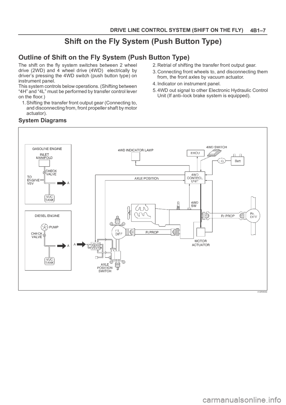
Shift on the Fly System (Push Button Type)
Outline of Shift on the Fly System (Push Button Type)
The shift on the fly system switches between 2 wheel
drive (2WD) and 4 wheel drive (4WD) electrically by
driver’s pressing the 4WD switch (push button type) on
instrument panel.
This system controls below operations. (Shifting between
“4H” and “4L” must be performed by transfer control lever
on the floor.)
1. Shifting the transfer front output gear (Connecting to,
and disconnecting from, front propeller shaft by motor
actuator).2. Retrial of shifting the transfer front output gear.
3. Connecting front wheels to, and disconnecting them
from, the front axles by vacuum actuator.
4. Indicator on instrument panel.
5. 4WD out signal to other Electronic Hydraulic Control
Unit (If anti–lock brake system is equipped).
System Diagrams
412RW050
Page 541 of 6000
4B1–8
DRIVE LINE CONTROL SYSTEM (SHIFT ON THE FLY)
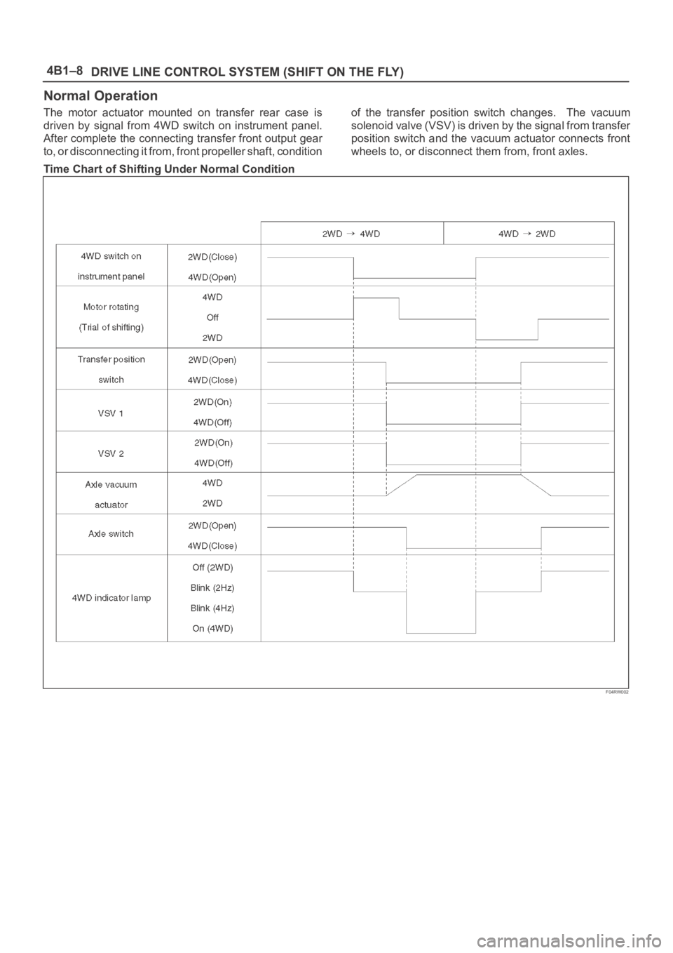
Normal Operation
The motor actuator mounted on transfer rear case is
driven by signal from 4WD switch on instrument panel.
After complete the connecting transfer front output gear
to, or disconnecting it from, front propeller shaft, conditionof the transfer position switch changes. The vacuum
solenoid valve (VSV) is driven by the signal from transfer
position switch and the vacuum actuator connects front
wheels to, or disconnect them from, front axles.
Time Chart of Shifting Under Normal Condition
F04RW002
Page 542 of 6000
4B1–9 DRIVE LINE CONTROL SYSTEM (SHIFT ON THE FLY)
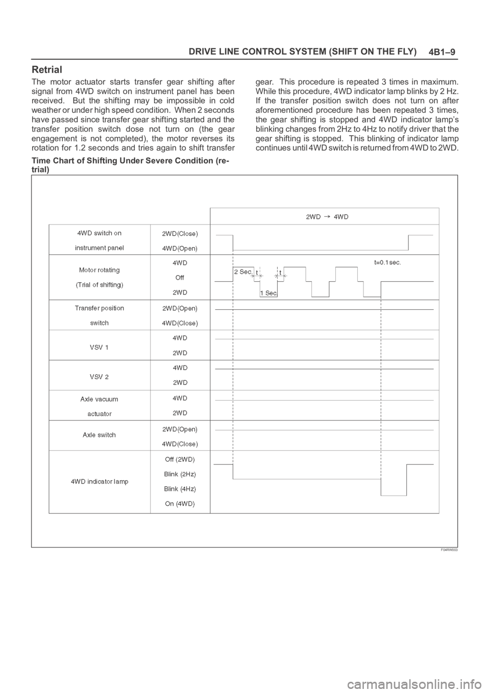
Retrial
The motor actuator starts transfer gear shifting after
signal from 4WD switch on instrument panel has been
received. But the shifting may be impossible in cold
weather or under high speed condition. When 2 seconds
have passed since transfer gear shifting started and the
transfer position switch dose not turn on (the gear
engagement is not completed), the motor reverses its
rotation for 1.2 seconds and tries again to shift transfergear. This procedure is repeated 3 times in maximum.
While this procedure, 4WD indicator lamp blinks by 2 Hz.
If the transfer position switch does not turn on after
aforementioned procedure has been repeated 3 times,
the gear shifting is stopped and 4WD indicator lamp’s
blinking changes from 2Hz to 4Hz to notify driver that the
gear shifting is stopped. This blinking of indicator lamp
continues until 4WD switch is returned from 4WD to 2WD.
Time Chart of Shifting Under Severe Condition (re-
trial)
F04RW003
Page 543 of 6000
4B1–10
DRIVE LINE CONTROL SYSTEM (SHIFT ON THE FLY)
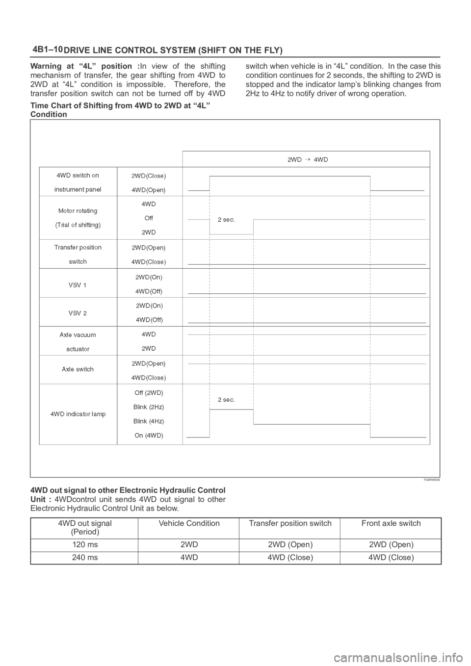
Warning at “4L” position :In view of the shifting
mechanism of transfer, the gear shifting from 4WD to
2WD at “4L” condition is impossible. Therefore, the
transfer position switch can not be turned off by 4WDswitch when vehicle is in “4L” condition. In the case this
condition continues for 2 seconds, the shifting to 2WD is
stopped and the indicator lamp’s blinking changes from
2Hz to 4Hz to notify driver of wrong operation.
Time Chart of Shifting from 4WD to 2WD at “4L”
Condition
F04RW005
4WD out signal to other Electronic Hydraulic Control
Unit : 4WDcontrol unit sends 4WD out signal to other
Electronic Hydraulic Control Unit as below.
4WD out signal
(Period)
Vehicle ConditionTransfer position switchFront axle switch
120 ms2WD2WD (Open)2WD (Open)
240 ms4WD4WD (Close)4WD (Close)
Page 544 of 6000
4B1–11 DRIVE LINE CONTROL SYSTEM (SHIFT ON THE FLY)
Functions of Indicator Lamp
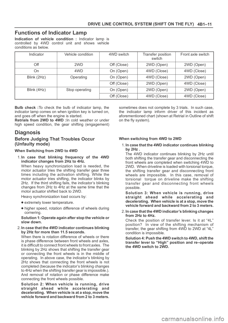
Indication of vehicle condition : Indicator lamp is
controlled by 4WD control unit and shows vehicle
conditions as below.
Indicator
Vehicle condition4WD switchTransfer position
switchFront axle switch
Off2WDOff (Close)2WD (Open)2WD (Open)
On4WDOn (Open)4WD (Close)4WD (Close)
Blink (2Hz)OperatingOn (Open)4WD (Close)2WD (Open)
Off (Close)2WD (Open)4WD (Close)
Blink (4Hz)Stop operatingOn (Open)2WD (Open)2WD (Open)
Off (Close)4WD (Close)4WD (Close)
Bulb check :To check the bulb of indicator lamp, the
indicator lamp comes on when ignition key is turned on,
and goes off when the engine is started.
Retrials from 2WD to 4WD :In cold weather or under
high speed condition, the gear shifting (engagement)sometimes does not complete by 3 trials. In such case,
the indicator lamp inform driver of this incident as
aforementioned chart (shown at Retrial in Outline of shift
on the fly system).
Diagnosis
Before Judging That Troubles Occur
(Unfaulty mode)
When Switching from 2WD to 4WD
1.In case that blinking frequency of the 4WD
indicator changes from 2Hz to 4Hz.
When heavy synchronization load is needed, the
motor actuator tries the shifting transfer gear three
times including the activation shifting. While the
motor actuator tries shifting, the indicator blinks by
2Hz. If the third shifting fails, the indicator’s blinking
changes from 2Hz to 4Hz at the same time that the
motor actuator shifted back to 2WD.
Heavy synchronization load occurs by:
extremely lower temperature.
higher speed, rotation difference of wheels during
cornering.
Solution 1: Operate again after stop the vehicle or
slow down.
2.In case that the 4WD indicator continues blinking
by 2Hz for more than 11.5 seconds.
When there is rotation difference of wheels or there
is phase difference between front wheels and axles,
it is difficult to connect front wheels to front axles. The
blinking by 2Hz shows that shifting the transfer gear
or connecting the front wheels is in the middle of
operating. In above case, the indicator’s blinking by
2Hz shows that connecting the front wheels is not
completed (because the indicator’s blinking changes
to 4Hz when the shifting transfer gear is impossible.).
And removal of rotation or phase difference make
connecting the front wheels possible.
Solution 2: When vehicle is running, drive
straight ahead while accelerating and
decelerating. When vehicle is at a stop, move the
vehicle forward and backward from 2 to 3 meters.When switching from 4WD to 2WD
1.In case that the 4WD indicator continues blinking
by 2Hz .
The 4WD indicator continues blinking by 2Hz until
both shifting the transfer gear and disconnecting the
front wheels are completed when switching 4WD to
2WD. When driveline is loaded with torsional torque,
the shifting transfer gear and disconnecting front
wheels are impossible. In this case, removal of
torsional torque on driveline make the shifting
transfer gear and disconnecting front wheels
possible.
Solution 3: When vehicle is running, drive
straight ahead while accelerating and
decelerating. When vehicle is at a stop, move the
vehicle forward and backward from 2 to 3 meters.
2.In case that the 4WD indicator’s blinking changes
from 2Hz to 4Hz.
Check the position of transfer lever. Is it at “4L”
position? In view of the shifting mechanism of
transfer, the gear shifting from 4WD to 2WD at “4L”
condition is impossible.
Solution 4: Push the 4WD switch to 4WD, shift the
transfer lever to “High” position and re–operate
the 4WD switch to 2WD.
Page 558 of 6000
4B1–25 DRIVE LINE CONTROL SYSTEM (SHIFT ON THE FLY)
Diagnosis of the Faults Based on the
Status of 4WD Indicator Lamp, 4WD
Switch and T/F Change Lever
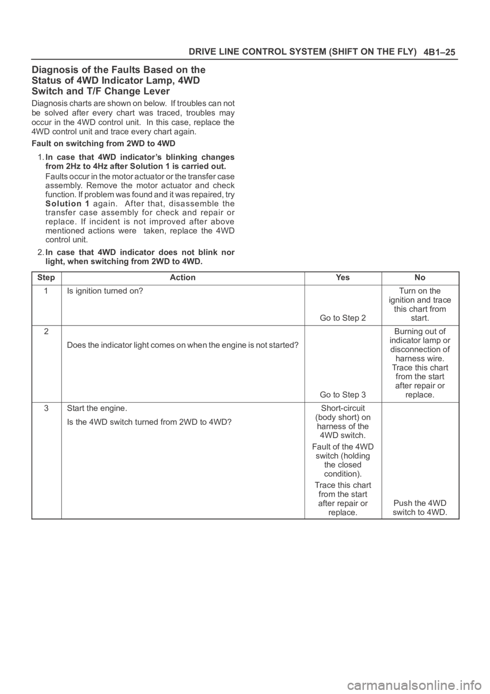
Diagnosis charts are shown on below. If troubles can not
be solved after every chart was traced, troubles may
occur in the 4WD control unit. In this case, replace the
4WD control unit and trace every chart again.
Fault on switching from 2WD to 4WD
1.In case that 4WD indicator’s blinking changes
from 2Hz to 4Hz after Solution 1 is carried out.
Faults occur in the motor actuator or the transfer case
assembly. Remove the motor actuator and check
function. If problem was found and it was repaired, try
Solution 1 again. After that, disassemble the
transfer case assembly for check and repair or
replace. If incident is not improved after above
mentioned actions were taken, replace the 4WD
control unit.
2.In case that 4WD indicator does not blink nor
light, when switching from 2WD to 4WD.
Step
ActionYe sNo
1Is ignition turned on?
Go to Step 2
Turn on the
ignition and trace
this chart from
start.
2
Does the indicator light comes on when the engine is not started?
Go to Step 3
Burning out of
indicator lamp or
disconnection of
harness wire.
Trace this chart
from the start
after repair or
replace.
3Start the engine.
Is the 4WD switch turned from 2WD to 4WD?Short-circuit
(body short) on
harness of the
4WD switch.
Fault of the 4WD
switch (holding
the closed
condition).
Trace this chart
from the start
after repair or
replace.
Push the 4WD
switch to 4WD.
Page 559 of 6000

4B1–26
DRIVE LINE CONTROL SYSTEM (SHIFT ON THE FLY)
3.Case that the indicator keeps blinking by 2Hz
after aforementioned Solution 2 is carried out.
Step
ActionYe sNo
1Check the air pressure and wear of all tires.
Were problems found?Try Solution 2
after adjust the
air pressure and
replace worn
tires.
Go to Step 2
2
Can the transfer lever be operated from High to 4L or vice versa?
Go to Step 3
Disconnection of
the motor
actuator harness
wiring. Trace this
chart from the
start after repair
or replace.
Faults on the
motor actuator.
Trace this chart
from the start
after replace.
Internal faults of
transfer case.
Disassemble the
transfer case for
check. Trace this
chart from the
start after repair
or replace.
3Pull out the hoses from vacuum actuator and operate 4WD
switch.
Is there negative pressure on either of hoses?
Go to Step 4
Faults on the
transfer position
switch or its
harness. Trace
this chart from
the start after
repair or replace.
Faults on the
VSV main body,
its harness or
vacuuming
system. Trace
the front axle
diagnosis chart in
this section.
After that, trace
this chart from
the start.
4Check the axle switch.
Were problems found?
Internal faults on
axle switch.
Trace this chart
from the start
after replace.
Disconnection on
the axle harness.
Trace this chart
from the start
after repair or
replace.
Faults on Front
Axle ASM. Trace
the front axle
diagnosis chart in
this section.
After that, trace
this chart from
the start.
Page 560 of 6000

4B1–27 DRIVE LINE CONTROL SYSTEM (SHIFT ON THE FLY)
Fault on switching from 4WD to 2WD
1.Case that indicator does not blink nor turn out.
Step
ActionYe sNo
1
Does the indicator turn out by ignition off?Go to Step 2
Short circuit of
the indicator
harness.
2
Is the 4WD switch on 2WD position?
Disconnection on
the 4WD switch
harness or
breakdown of the
4WD switch in
open state.
Trace this chart
from the start
after repair or
replace.
Turn the 4WD
switch to 2WD
position. Trace
this chart from
the start.