sensor OPEL FRONTERA 1998 Workshop Manual
[x] Cancel search | Manufacturer: OPEL, Model Year: 1998, Model line: FRONTERA, Model: OPEL FRONTERA 1998Pages: 6000, PDF Size: 97 MB
Page 1187 of 6000
6E–70
ENGINE DRIVEABILITY AND EMISSIONS
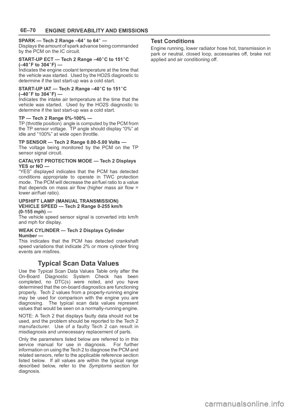
SPARK — Tech 2 Range –64 to 64 —
Displays the amount of spark advance being commanded
by the PCM on the IC circuit.
START-UP ECT — Tech 2 Range –40
C to 151C
(–40
F to 304F) —
Indicates the engine coolant temperature at the time that
the vehicle was started. Used by the HO2S diagnostic to
determine if the last start-up was a cold start.
START-UP IAT — Tech 2 Range –40
C to 151C
(–40
F to 304F) —
Indicates the intake air temperature at the time that the
vehicle was started. Used by the HO2S diagnostic to
determine if the last start-up was a cold start.
TP — Tech 2 Range 0%-100% —
TP (throttle position) angle is computed by the PCM from
the TP sensor voltage. TP angle should display “0%” at
idle and “100%” at wide open throttle.
TP SENSOR — Tech 2 Range 0.00-5.00 Volts —
The voltage being monitored by the PCM on the TP
sensor signal circuit.
CATALYST PROTECTION MODE — Tech 2 Displays
YES or NO —
“YES” displayed indicates that the PCM has detected
conditions appropriate to operate in TWC protection
mode. The PCM will decrease the air/fuel ratio to a value
that depends on mass air flow (higher mass air flow =
lower air/fuel ratio).
UPSHIFT LAMP (MANUAL TRANSMISSION)
VEHICLE SPEED — Tech 2 Range 0-255 km/h
(0-155 mph) —
The vehicle speed sensor signal is converted into km/h
and mph for display.
WEAK CYLINDER — Tech 2 Displays Cylinder
Number —
This indicates that the PCM has detected crankshaft
speed variations that indicate 2% or more cylinder firing
events are misfires.
Typical Scan Data Values
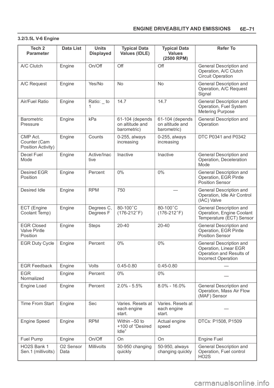
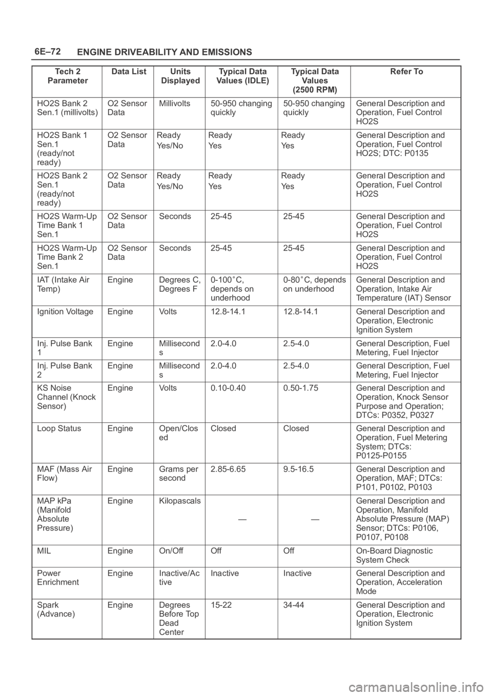
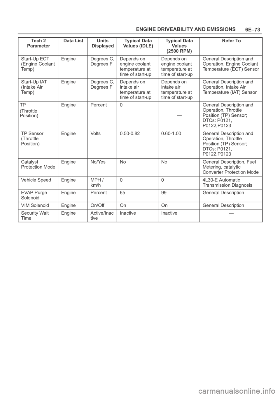
Use the Typical Scan Data Values Table only after the
On-Board Diagnostic System Check has been
completed, no DTC(s) were noted, and you have
determined that the on-board diagnostics are functioning
properly. Tech 2 values from a properly-running engine
may be used for comparison with the engine you are
diagnosing. The typical scan data values represent
values that would be seen on a normally-running engine.
NOTE: A Tech 2 that displays faulty data should not be
used, and the problem should be reported to the Tech 2
manufacturer. Use of a faulty Tech 2 can result in
misdiagnosis and unnecessary replacement of parts.
Only the parameters listed below are referred to in this
service manual for use in diagnosis. For further
information on using the Tech 2 to diagnose the PCM and
related sensors, refer to the applicable reference section
listed below. If all values are within the typical range
described below, refer to the
Symptoms section for
diagnosis.
Test Conditions
Engine running, lower radiator hose hot, transmission in
park or neutral, closed loop, accessaries off, brake not
applied and air conditioning off.
Page 1188 of 6000
6E–71 ENGINE DRIVEABILITY AND EMISSIONS
3.2/3.5L V-6 Engine
Te c h 2
Parameter
Data ListUnits
DisplayedTypical Data
Values (IDLE)Typical Data
Va l u e s
(2500 RPM)Refer To
A/C ClutchEngineOn/OffOffOffGeneral Description and
Operation, A/C Clutch
Circuit Operation
A/C RequestEngineYe s / N oNoNoGeneral Description and
Operation, A/C Request
Signal
Air/Fuel RatioEngineRatio: _ to
114.714.7General Description and
Operation, Fuel System
Metering Purpose
Barometric
PressureEnginekPa61-104 (depends
on altitude and
barometric)61-104 (depends
on altitude and
barometric)General Description and
Operation
CMP Act.
Counter (Cam
Position Activity)EngineCounts0-255, always
increasing0-255, always
increasingDTC P0341 and P0342
Decel Fuel
ModeEngineActive/Inac
tiveInactiveInactiveGeneral Description and
Operation, Deceleration
Mode
Desired EGR
PositionEnginePercent0%0%General Description and
Operation, EGR Pintle
Position Sensor
Desired IdleEngineRPM750—General Description and
Operation, Idle Air Control
(IAC) Valve
ECT (Engine
Coolant Temp)EngineDegrees C,
Degrees F80-100C
(176-212
F)
80-100C
(176-212
F)
General Description and
Operation, Engine Coolant
Temperature (ECT) Sensor
EGR Closed
Valve Pintle
PositionEngineSteps20-4020-40General Description and
Operation, EGR Pintle
Position Sensor
EGR Duty CycleEnginePercent0%0%General Description and
Operation, Linear EGR
Operation and Results of
Incorrect Operation
EGR FeedbackEngineVo l t s0.45-0.800.45-0.80—
EGR
NormalizedEnginePercent0%0%—
Engine LoadEnginePercent2.0% - 5.5%8.0% - 16.0%General Description and
Operation, Mass Air Flow
(MAF) Sensor
Time From StartEngineSecVaries. Resets at
each engine
start.Varies. Resets at
each engine
start.
—
Engine SpeedEngineRPMWithin –50 to
+100 of “Desired
Idle”Actual engine
speedDTCs: P1508, P1509
Fuel PumpEngineOn/OffOnOnEngine Fuel
HO2S Bank 1
Sen.1 (millivolts)O2 Sensor
DataMillivolts50-950 changing
quickly50-950, always
changing quicklyGeneral Description and
Operation, Fuel control
HO2S
Page 1189 of 6000
6E–72
ENGINE DRIVEABILITY AND EMISSIONS
Te c h 2
ParameterRefer To Typical Data
Va l u e s
(2500 RPM) Typical Data
Values (IDLE) Units
Displayed Data List
HO2S Bank 2
Sen.1 (millivolts)O2 Sensor
DataMillivolts50-950 changing
quickly50-950 changing
quicklyGeneral Description and
Operation, Fuel Control
HO2S
HO2S Bank 1
Sen.1
(ready/not
ready)O2 Sensor
DataReady
Ye s / N oReady
Ye sReady
Ye sGeneral Description and
Operation, Fuel Control
HO2S; DTC: P0135
HO2S Bank 2
Sen.1
(ready/not
ready)O2 Sensor
DataReady
Ye s / N oReady
Ye sReady
Ye sGeneral Description and
Operation, Fuel Control
HO2S
HO2S Warm-Up
Time Bank 1
Sen.1O2 Sensor
DataSeconds25-4525-45General Description and
Operation, Fuel Control
HO2S
HO2S Warm-Up
Time Bank 2
Sen.1O2 Sensor
DataSeconds25-4525-45General Description and
Operation, Fuel Control
HO2S
IAT (Intake Air
Te m p )EngineDegrees C,
Degrees F0-100C,
depends on
underhood0-80C, depends
on underhoodGeneral Description and
Operation, Intake Air
Temperature (IAT) Sensor
Ignition VoltageEngineVo l t s12.8-14.112.8-14.1General Description and
Operation, Electronic
Ignition System
Inj. Pulse Bank
1EngineMillisecond
s2.0-4.02.5-4.0General Description, Fuel
Metering, Fuel Injector
Inj. Pulse Bank
2EngineMillisecond
s2.0-4.02.5-4.0General Description, Fuel
Metering, Fuel Injector
KS Noise
Channel (Knock
Sensor)EngineVo l t s0.10-0.400.50-1.75General Description and
Operation, Knock Sensor
Purpose and Operation;
DTCs: P0352, P0327
Loop StatusEngineOpen/Clos
edClosedClosedGeneral Description and
Operation, Fuel Metering
System; DTCs:
P0125-P0155
MAF (Mass Air
Flow)EngineGrams per
second2.85-6.659.5-16.5General Description and
Operation, MAF; DTCs:
P101, P0102, P0103
MAP kPa
(Manifold
Absolute
Pressure)EngineKilopascals
——
General Description and
Operation, Manifold
Absolute Pressure (MAP)
Sensor; DTCs: P0106,
P0107, P0108
MILEngineOn/OffOffOffOn-Board Diagnostic
System Check
Power
EnrichmentEngineInactive/Ac
tiveInactiveInactiveGeneral Description and
Operation, Acceleration
Mode
Spark
(Advance)EngineDegrees
Before Top
Dead
Center15-2234-44General Description and
Operation, Electronic
Ignition System
Page 1190 of 6000
6E–73 ENGINE DRIVEABILITY AND EMISSIONS
Te c h 2
ParameterRefer To Typical Data
Va l u e s
(2500 RPM) Typical Data
Values (IDLE) Units
Displayed Data List
Start-Up ECT
(Engine Coolant
Te m p )EngineDegrees C,
Degrees FDepends on
engine coolant
temperature at
time of start-upDepends on
engine coolant
temperature at
time of start-upGeneral Description and
Operation, Engine Coolant
Temperature (ECT) Sensor
Start-Up IAT
(Intake Air
Te m p )EngineDegrees C,
Degrees FDepends on
intake air
temperature at
time of start-upDepends on
intake air
temperature at
time of start-upGeneral Description and
Operation, Intake Air
Temperature (IAT) Sensor
TP
(Throttle
Position)EnginePercent0
—
General Description and
Operation, Throttle
Position (TP) Sensor;
DTCs: P0121,
P0122,P0123
TP Sensor
(Throttle
Position)EngineVo l t s0.50-0.820.60-1.00General Description and
Operation, Throttle
Position (TP) Sensor;
DTCs: P0121,
P0122,P0123
Catalyst
Protection ModeEngineNo/YesNoNoGeneral Description, Fuel
Metering, catalytic
Converter Protection Mode
Vehicle SpeedEngineMPH /
km/h004L30-E Automatic
Transmission Diagnosis
EVAP Purge
SolenoidEnginePercent6599General Description
VIM SolenoidEngineOn/OffOnOnGeneral Description
Security Wait
TimeEngineActive/Inac
tiveInactiveInactive—
Page 1197 of 6000
6E–80
ENGINE DRIVEABILITY AND EMISSIONS
Circuit Description
The electronic Ignition system uses a coil-at-plug method
of spark distribution. In this type of ignition system, the
powertrain control module (PCM) triggers the correct
driver inside the ignition coil, which then triggers the
correct ignition coil based on the 58X signal received from
the crankshaft position sensor (CKP). The spark plug
connected to the coil fires when the ICM opens the ground
circuit for the coil’s primary circuit.
During crank, the PCM monitors the CKP 58X signal. The
CKP signal is used to determine which cylinder will fire
first. After the CKP 58X signal has been processed by the
PCM, it will command all six injectors to allow a priming
shot of fuel for all the cylinders. After the priming, the
injectors are left “OFF” during the next six 58X reference
pulses from the CKP. This allows each cylinder a chance
to use the fuel from the priming shot. During this waiting
period, a camshaft position (CMP) signal pulse will have
been received by the PCM. The CMP signal allows the
PCM to operate the injectors sequentially based on
camshaft position. If the camshaft position signal is not
present at start-up, the PCM will begin sequential fuel
delivery with a 1-in-6 chance that fuel delivery is correct.
The engine will run without a CMP signal, but will set a
DTC code.
Diagnostic Aids
An intermittent problem may be caused by a poor
connection, rubbed-through wire insulation or a wire
broken inside the insulation. Check for the following
items:
Poor connection or damaged harness – Inspect the
PCM harness and connectors for improper mating,
broken locks, improperly formed or damaged
terminals, poor terminal-to-wire connection, and
damaged harness.
Faulty engine coolant temperature sensor – Using
Tech 2, compare engine coolant temperature with
intake air temperature on a completely cool engine.
Engine coolant temperature should be within 10
C of
intake air temperature. If not, replace the ECT sensor.
Test Description
Number(s) below refer to the step number(s) on the
Diagnostic Chart.
5. An obvious cause of low fuel pressure would be an
empty fuel tank.
6. The engine will easily start and run if a few injectors
are disabled. It is not necessary to test all injectors
at this time since this step is only a test to verify that
all of the injectors have not been disabled by fuel
contamination.
7. A blinking test light verifies that the PCM is
monitoring the 58X crankshaft reference signal and
is capable of activating the injectors. If there is an
open or shorted driver circuit, DTCs 201-206 should
be set.
19.By using a spark tester, each ignition coil’s ability to
produce 25,000 volts is verified.
25.If there is an open or shorted driver circuit, DTCs
201-206 should be set. All six injector driver circuits
can be checked at one time without removing the
intake manifold if a 5-8840-2636-0 test light is
available. This is the alternative procedure:
With the ignition “OFF,” disconnect the gray
connector located at the rear of the air filter, attached
to a bracket on the purge canister.
Connect test light 5-8840-2636-0 to the connector.
Do any of the light constantly illuminate or fail to blink
when the engine is cranked? If so, repair the short or
open circuit, or replace the PCM if indicated.
This procedure only tests the driver circuit as far as the
test connection, so step 31 is added to test the circuit all
the way to the injector.
Page 1199 of 6000
6E–82
ENGINE DRIVEABILITY AND EMISSIONS
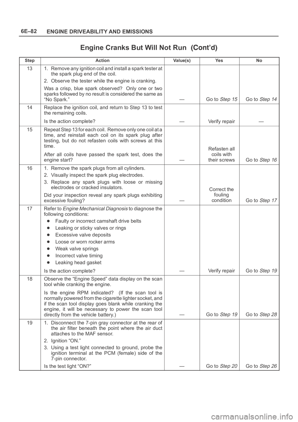
Engine Cranks But Will Not Run
StepNo Ye s Va l u e ( s ) Action
131. Remove any ignition coil and install a spark tester at
the spark plug end of the coil.
2. Observe the tester while the engine is cranking.
Was a crisp, blue spark observed? Only one or two
sparks followed by no result is considered the same as
“No Spark.”
—Go to Step 15Go to Step 14
14Replace the ignition coil, and return to Step 13 to test
the remaining coils.
Is the action complete?
—Verify repair—
15Repeat Step 13 for each coil. Remove only one coil at a
time, and reinstall each coil on its spark plug after
testing, but do not refasten coils with screws at this
time.
After all coils have passed the spark test, does the
engine start?
—
Refasten all
coils with
their screws
Go to Step 16
161. Remove the spark plugs from all cylinders.
2. Visually inspect the spark plug electrodes.
3. Replace any spark plugs with loose or missing
electrodes or cracked insulators.
Did your inspection reveal any spark plugs exhibiting
excessive fouling?
—
Correct the
fouling
condition
Go to Step 17
17Refer to Engine Mechanical Diagnosis to diagnose the
following conditions:
Faulty or incorrect camshaft drive belts
Leaking or sticky valves or rings
Excessive valve deposits
Loose or worn rocker arms
Weak valve springs
Incorrect valve timing
Leaking head gasket
Is the action complete?
—Verify repairGo to Step 19
18Observe the “Engine Speed” data display on the scan
tool while cranking the engine.
Is the engine RPM indicated? (If the scan tool is
normally powered from the cigarette lighter socket, and
if the scan tool display goes blank while cranking the
engine, it will be necessary to power the scan tool
directly from the vehicle battery.)
—Go to Step 19Go to Step 28
191. Disconnect the 7-pin gray connector at the rear of
the air filter beneath the point where the air duct
attaches to the MAF sensor.
2. Ignition “ON.”
3. Using a test light connected to ground, probe the
ignition terminal at the PCM (female) side of the
7-pin connector.
Is the test light “ON?”
—Go to Step 20Go to Step 26
Page 1200 of 6000
6E–83 ENGINE DRIVEABILITY AND EMISSIONS
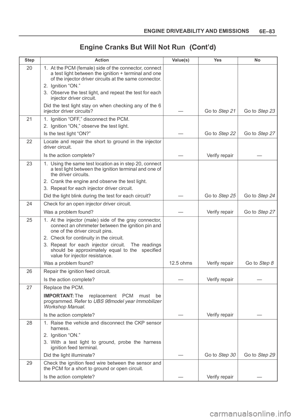
Engine Cranks But Will Not Run
StepNo Ye s Va l u e ( s ) Action
201. At the PCM (female) side of the connector, connect
a test light between the ignition + terminal and one
of the injector driver circuits at the same connector.
2. Ignition “ON.”
3. Observe the test light, and repeat the test for each
injector driver circuit.
Did the test light stay on when checking any of the 6
injector driver circuits?
—Go to Step 21Go to Step 23
211. Ignition “OFF,” disconnect the PCM.
2. Ignition “ON,” observe the test light.
Is the test light “ON?”
—Go to Step 22Go to Step 27
22Locate and repair the short to ground in the injector
driver circuit.
Is the action complete?
—Verify repair—
231. Using the same test location as in step 20, connect
a test light between the ignition terminal and one of
the driver circuits.
2. Crank the engine and observe the test light.
3. Repeat for each injector driver circuit.
Did the light blink during the test for each circuit?
—Go to Step 25Go to Step 24
24Check for an open injector driver circuit.
Was a problem found?
—Verify repairGo to Step 27
251. At the injector (male) side of the gray connector,
connect an ohmmeter between the ignition pin and
one of the driver circuit pins.
2. Check for continuity in the circuit.
3. Repeat for each injector circuit. The readings
should be approximately equal to the specified
value for injector resistance.
Was a problem found?
12.5 ohmsVerify repairGo to Step 8
26Repair the ignition feed circuit.
Is the action complete?
—Verify repair—
27Replace the PCM.
IMPORTANT:The replacement PCM must be
programmed. Refer to
UBS 98model year Immobilizer
Workshop Manual.
Is the action complete?—Verify repair—
281. Raise the vehicle and disconnect the CKP sensor
harness.
2. Ignition “ON.”
3. With a test light to ground, probe the harness
ignition feed terminal.
Did the light illuminate?
—Go to Step 30Go to Step 29
29Check the ignition feed wire between the sensor and
the PCM for a short to ground or open circuit.
Is the action complete?
—Verify repair—
Page 1201 of 6000
6E–84
ENGINE DRIVEABILITY AND EMISSIONS
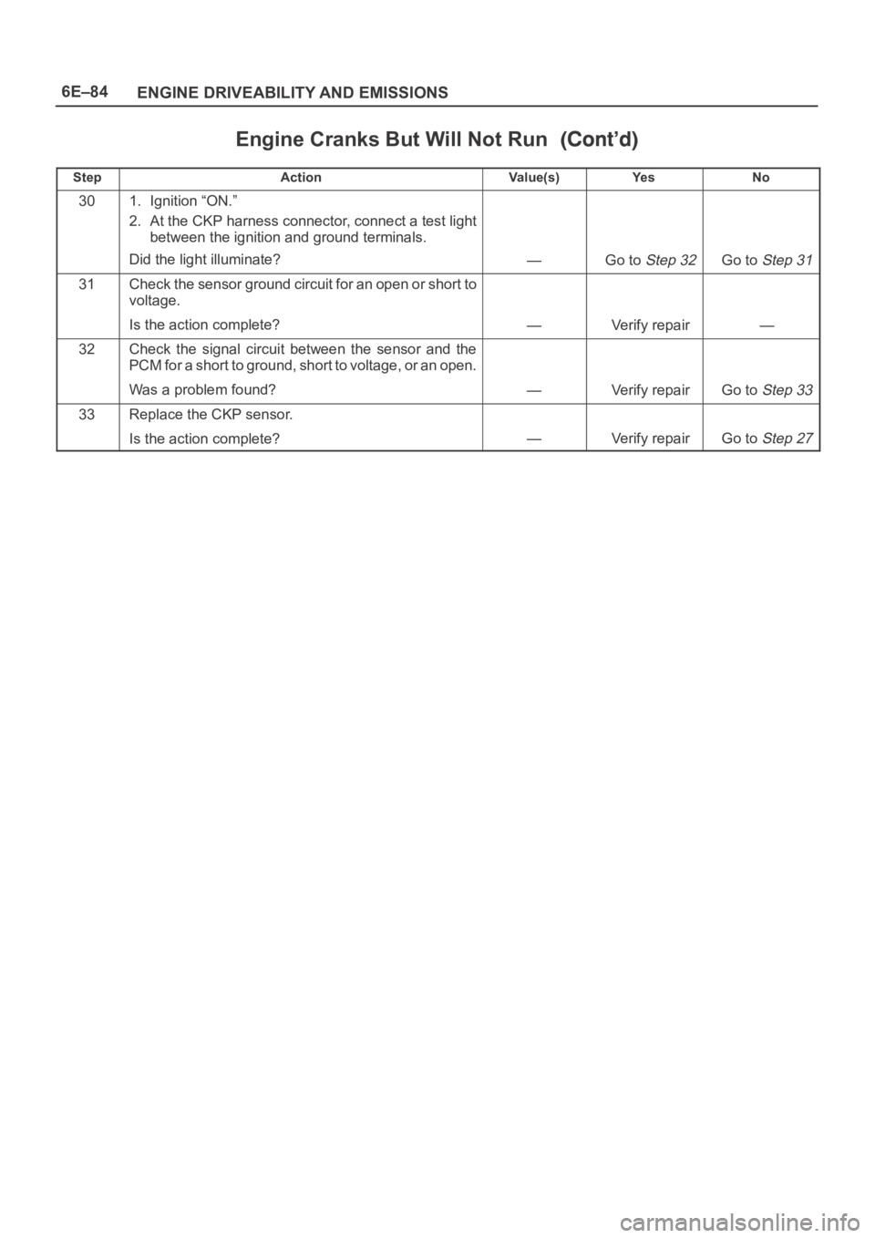
Engine Cranks But Will Not Run
StepNo Ye s Va l u e ( s ) Action
301. Ignition “ON.”
2. At the CKP harness connector, connect a test light
between the ignition and ground terminals.
Did the light illuminate?
—Go to Step 32Go to Step 31
31Check the sensor ground circuit for an open or short to
voltage.
Is the action complete?
—Verify repair—
32Check the signal circuit between the sensor and the
PCM for a short to ground, short to voltage, or an open.
Was a problem found?
—Verify repairGo to Step 33
33Replace the CKP sensor.
Is the action complete?
—Verify repairGo to Step 27
Page 1206 of 6000
6E–89 ENGINE DRIVEABILITY AND EMISSIONS
The valve or valve seat within the fuel pressure
regulator.
The fuel injector(s).
4. Fuel pressure that drops off during acceleration,
cruise, or hard cornering may case a lean condition.
A lean condition can cause a loss of power, surging,
or misfire. A lean condition can be diagnosed using
a Tech II Tech 2. If an extremely lean condition
occurs, the oxygen sensor(s) will stop toggling. The
oxygen sensor output voltage(s) will drop below 500
mV. Also, the fuel injector pulse width will increase.
IMPORTANT:Make sure the fuel system is not
operating in the “Fuel Cut-Off Mode.”
When the engine is at idle, the manifold pressure is
low (high vacuum). This low pressure (high vacuum)
is applied to the fuel pressure regulator diaphragm.
The low pressure (high vacuum) will offset the
pressure being applied to the fuel pressure regulator
diaphragm by the spring inside the fuel pressure
regulator. When this happens, the result is lower fuel
pressure. The fuel pressure at idle will vary slightly as
the barometric pressure changes, but the fuel
pressure at idle should always be less than the fuel
pressure noted in step 2 with the engine “OFF.”
16.Check the spark plug associated with a particular
fuel injector for fouling or saturation in order to
determine if that particular fuel injector is leaking. If
checking the spark plug associated with a particular
fuel injector for fouling or saturation does not
determine that a particular fuel injector is leaking,
use the following procedure:
Remove the fuel rail, but leave the fuel lines and
injectors connected to the fuel rail. Refer to
Fuel Rail
Assembly
in On-Vehicle Service.
Lift the fuel rail just enough to leave the fuel injector
nozzles in the fuel injector ports.
CAUTION: In order to reduce the risk of fire and
personal injury that may result from fuel spraying on
the engine, verify that the fuel rail is positioned over
the fuel injector ports and verify that the fuel injector
retaining clips are intact.
Pressurize the fuel system by connecting a 10 amp
fused jumper between B+ and the fuel pump relay
connector.
Visually and physically inspect the fuel injector
nozzles for leaks.
17.A rich condition may result from the fuel pressure
being above 376 kPa (55 psi). A rich condition may
cause a DTC P0132 or a DTC P0172 to set.
Driveability conditions associated with rich
conditions can include hard starting (followed by
black smoke) and a strong sulfur smell in the
exhaust.20.This test determines if the high fuel pressure is due
to a restricted fuel return line or if the high fuel
pressure is due to a faulty fuel pressure regulator.
21.A lean condition may result from fuel pressure
below 333 kPa (48 psi). A lean condition may
cause a DTC P0131 or a DTC P0171 to set.
Driveability conditions associated with lean
conditions can include hard starting (when the
engine is cold ), hesitation, poor driveability, lack of
power, surging , and misfiring.
22.Restricting the fuel return line causes the fuel
pressure to rise above the regulated fuel pressure.
Command the fuel pump “ON” with Tech 2. The fuel
pressure should rise above 376 kPa (55 psi) as the
fuel return line becomes partially closed.
NOTE: Do not allow the fuel pressure to exceed 414 kPa
( 6 0 p s i ) . F u e l p r e s s u r e i n e x c e s s o f 4 1 4 k P a ( 6 0 p s i ) m a y
damage the fuel pressure regulator.
CAUTION: To reduce the risk of fire and personal
injury:
It is necessary to relieve fuel system pressure
before connecting a fuel pressure gauge. Refer to
Fuel Pressure Relief Procedure, below.
A small amount of fuel may be released when
disconnecting the fuel lines. Cover fuel line
fittings with a shop towel before disconnecting, to
catch any fuel that may leak out. Place the towel in
an approved container when the disconnect is
completed.
Fuel Pressure Relief Procedure
1. Remove the fuel cap.
2. Remove the fuel pump relay from the underhood
relay center.
3. Start the engine and allow it to stall.
4. Crank the engine for an additional 3 seconds.
Fuel Gauge Installation
1. Remove the shoulder fitting cap.
2. Install fuel gauge 5-8840-0378-0 to the fuel feed line
located in front of and above the right side valve train
cover.
3. Reinstall the fuel pump relay.
Page 1210 of 6000
6E–93 ENGINE DRIVEABILITY AND EMISSIONS
Idle Air Control (IAC) System Check
Circuit Description
The powertrain control module (PCM) controls engine
idle speed with the idle air control (IAC) valve. To increase
idle speed, the PCM retracts the IAC valve pintle away
from its seat, allowing more air to bypass the throttle bore.
To decrease idle speed, it extends the IAC valve pintle
towards its seat, reducing by pass air flow. Tech 2 will
read the PCM commands to the IAC valve in counts.
Higher counts indicate more air bypass (higher idle).
Lower counts indicate less air is allowed to bypass (lower
idle).
Diagnostic Aids
A slow, unstable, or fast idle may be caused by a non-IAC
system problem that cannot be overcome by the IAC
valve. Out of control range IAC Tech 2 counts will be
above 60 if idle is too low, and zero counts if idle is too
high. The following checks should be made to repair a
non-IAC system problem:
Vacuum leak (high idle) – If idle is too high, stop the
engine. Fully extend (low) IAC with the Tech 2. Start
the engine. If idle speed is above 800 RPM, locate and
correct the vacuum leak, including the PCV system.
Check for binding of the throttle blade or linkage.
Lean heated oxygen sensor signal (high air/fuel ratio) –
The idle speed may be too high or too low. Engine
speed may vary up and down, and disconnecting the
IAC valve does not help. Diagnostic trouble codes
P0131, P0151, P0171, or P0174 may be set. Tech 2
oxygen (O2) voltage will be less than 100 mV (0.1 V).
Check for low regulated fuel pressure, water in fuel, or
a restricted injector.
Rich heated oxygen sensor signal (low air/fuel ratio) –
The idle speed will be too low. Tech 2 IAC counts will
usually be above 80. The system is obviously rich and
may exhibit black smoke in the exhaust.
Tech 2 O2 voltage will be fixed at about 750 mV (0.75
V). Check for high fuel pressure, or a leaking or
sticking injector. A silicon-contaminated heated
oxygen sensor will show an O2 voltage slow to
respond on Tech 2.
Throttle body – Remove the IAC valve and inspect the
bore for foreign material.
IAC valve electrical connections – IAC valve
connections should be carefully checked for proper
contact.
PCV valve – An incorrect or faulty PCV valve may
result in an incorrect idle speed. Refer to
Diagnosis,
Rough Idle, Stalling.
If intermittent poor driveability or
idle symptoms are resolved by disconnecting the IAC,
carefully recheck the connections and valve terminal
resistance, or replace the IAC.
Test Description
Number(s) below refer to the step number(s) on the
Diagnostic Chart.
1. The Tech 2 is used to extend and retract the IAC
valve. Valve movement is verified by an engine
speed change. If no change in engine speed
occurs, the valve can be resettled when removed
from the throttle body.
2. This step checks the quality of the IAC movement in
step 1. Between 700 revolutions per minute (RPM)
and about 1500 RPM, the engine speed should
change smoothly with each flash of the tester light
in both extend and retract. If the IAC valve is
retracted beyond the control range (about 1500
RPM), it may take many flashes to extend the IAC
valve before engine speed will begin to drop. This
is normal on certain engines. Fully extending the
IAC may cause engine stall. This may be normal.