ground clearance OPEL FRONTERA 1998 User Guide
[x] Cancel search | Manufacturer: OPEL, Model Year: 1998, Model line: FRONTERA, Model: OPEL FRONTERA 1998Pages: 6000, PDF Size: 97 MB
Page 5004 of 6000

6E–347 ENGINE DRIVEABILITY AND EMISSIONS
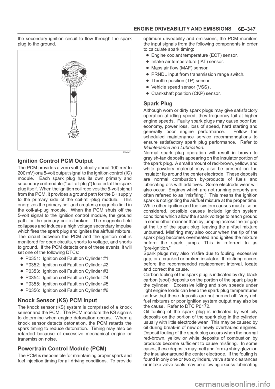
the secondary ignition circuit to flow through the spark
plug to the ground.
TS24047
Ignition Control PCM Output
The PCM provides a zero volt (actually about 100 mV to
200 mV) or a 5-volt output signal to the ignition control (IC)
module. Each spark plug has its own primary and
secondary coil module (”coil-at-plug”) located at the spark
plug itself. When the ignition coil receives the 5-volt signal
from the PCM, it provides a ground path for the B+ supply
to the primary side of the coil-at -plug module. This
energizes the primary coil and creates a magnetic field in
the coil-at-plug module. When the PCM shuts off the
5-volt signal to the ignition control module, the ground
path for the primary coil is broken. The magnetic field
collapses and induces a high voltage secondary impulse
which fires the spark plug and ignites the air/fuel mixture.
The circuit between the PCM and the ignition coil is
monitored for open circuits, shorts to voltage, and shorts
to ground. If the PCM detects one of these events, it will
set one of the following DTCs:
P0351: Ignition coil Fault on Cylinder #1
P0352: Ignition coil Fault on Cylinder #2
P0353: Ignition coil Fault on Cylinder #3
P0354: Ignition coil Fault on Cylinder #4
P0355: Ignition coil Fault on Cylinder #5
P0356: Ignition coil Fault on Cylinder #6
Knock Sensor (KS) PCM Input
The knock sensor (KS) system is comprised of a knock
sensor and the PCM. The PCM monitors the KS signals
to determine when engine detonation occurs. When a
knock sensor detects detonation, the PCM retards the
spark timing to reduce detonation. Timing may also be
retarded because of excessive mechanical engine or
transmission noise.
Powertrain Control Module (PCM)
The PCM is responsible for maintaining proper spark and
fuel injection timing for all driving conditions. To provideoptimum driveability and emissions, the PCM monitors
the input signals from the following components in order
to calculate spark timing:
Engine coolant temperature (ECT) sensor.
Intake air temperature (IAT) sensor.
Mass air flow (MAF) sensor.
PRNDL input from transmission range switch.
Throttle position (TP) sensor.
Vehicle speed sensor (VSS) .
Crankshaft position (CKP) sensor.
Spark Plug
Although worn or dirty spark plugs may give satisfactory
operation at idling speed, they frequency fail at higher
engine speeds. Faulty spark plugs may cause poor fuel
economy, power loss, loss of speed, hard starting and
generally poor engine performance. Follow the
scheduled maintenance service recommendations to
ensure satisfactory spark plug performance. Refer to
Maintenance and Lubrication.
Normal spark plug operation will result in brown to
grayish-tan deposits appearing on the insulator portion of
the spark plug. A small amount of red-brown, yellow, and
white powdery material may also be present on the
insulator tip around the center electrode. These deposits
are normal combustion by-products of fuels and
lubricating oils with additives. Some electrode wear will
also occur. Engines which are not running properly are
often referred to as “misfiring.” This means the ignition
spark is not igniting the air/fuel mixture at the proper time.
While other ignition and fuel system causes must also be
considered, possible causes include ignition system
conditions which allow the spark voltage to reach ground
in some other manner than by jumping across the air gap
at the tip of the spark plug, leaving the air/fuel mixture
unburned. Misfiring may also occur when the tip of the
spark plug becomes overheated and ignites the mixture
before the spark jumps. This is referred to as
“pre-ignition.”
Spark plugs may also misfire due to fouling, excessive
gap, or a cracked or broken insulator. If misfiring occurs
before the recommended replacement interval, locate
and correct the cause.
Carbon fouling of the spark plug is indicated by dry, black
carbon (soot) deposits on the portion of the spark plug in
the cylinder. Excessive idling and slow speeds under
light engine loads can keep the spark plug temperatures
so low that these deposits are not burned off. Very rich
fuel mixtures or poor ignition system output may also be
the cause. Refer to DTC P0172.
Oil fouling of the spark plug is indicated by wet oily
deposits on the portion of the spark plug in the cylinder,
usually with little electrode wear. This may be caused by
oil during break-in of new or newly overhauled engines.
Deposit fouling of the spark plug occurs when the normal
red-brown, yellow or white deposits of combustion by
products become sufficient to cause misfiring. In some
c a s e s , t h e s e d e p o s i t s m a y m e l t a n d f o r m a s h i n y g l a z e o n
the insulator around the center electrode. If the fouling is
found in only one or two cylinders, valve stem clearances
or intake valve seals may be allowing excess lubricating
Page 5275 of 6000

6A – 2 ENGINE MECHANICAL
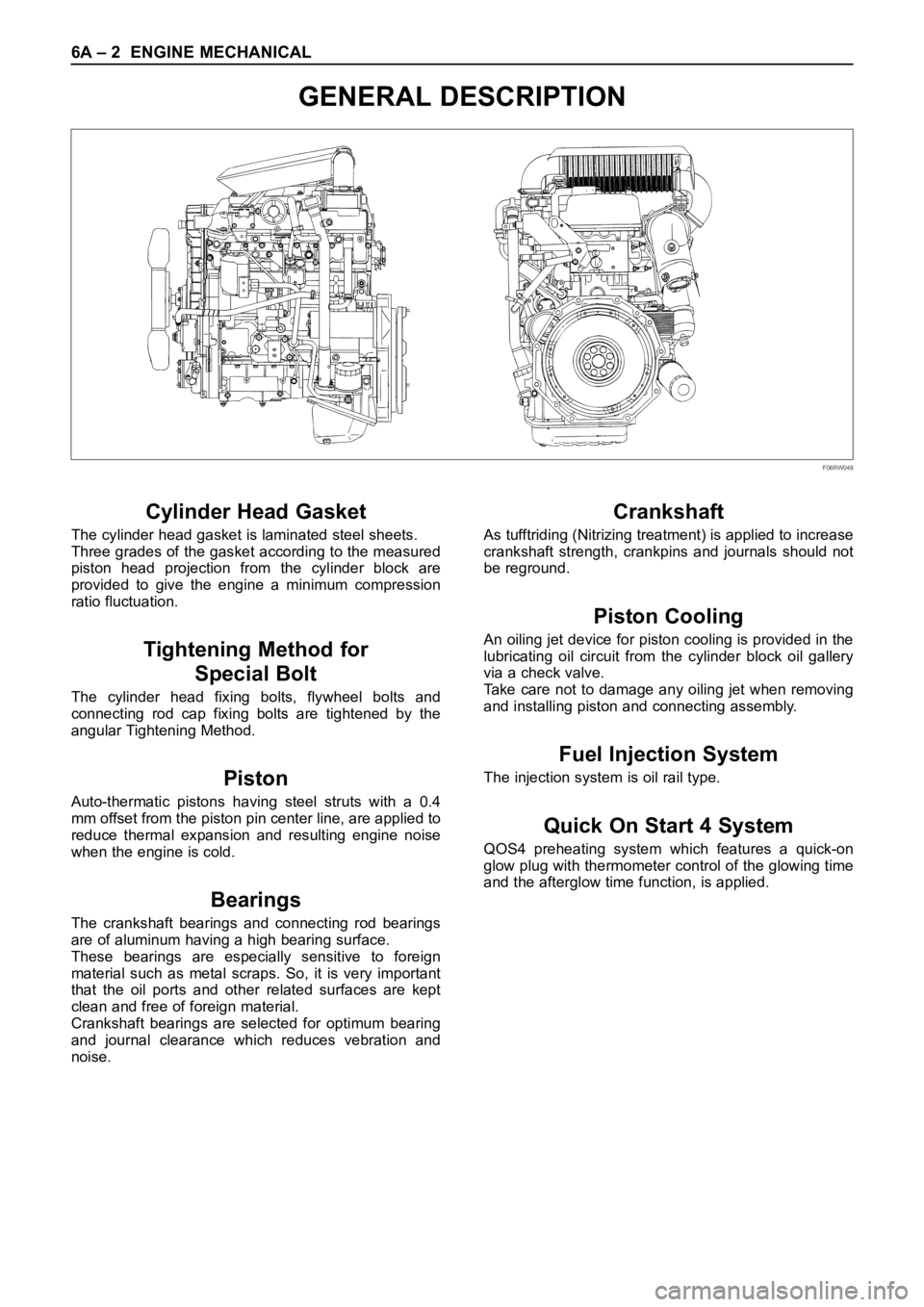
GENERAL DESCRIPTION
Cylinder Head Gasket
The cylinder head gasket is laminated steel sheets.
Three grades of the gasket according to the measured
piston head projection from the cylinder block are
provided to give the engine a minimum compression
ratio fluctuation.
Tightening Method for
Special Bolt
The cylinder head fixing bolts, flywheel bolts and
connecting rod cap fixing bolts are tightened by the
angular Tightening Method.
Piston
Auto-thermatic pistons having steel struts with a 0.4
mm offset from the piston pin center line, are applied to
reduce thermal expansion and resulting engine noise
when the engine is cold.
Bearings
The crankshaft bearings and connecting rod bearings
are of aluminum having a high bearing surface.
These bearings are especially sensitive to foreign
material such as metal scraps. So, it is very important
that the oil ports and other related surfaces are kept
clean and free of foreign material.
Crankshaft bearings are selected for optimum bearing
and journal clearance which reduces vebration and
noise.
Crankshaft
As tufftriding (Nitrizing treatment) is applied to increase
crankshaft strength, crankpins and journals should not
be reground.
Piston Cooling
An oiling jet device for piston cooling is provided in the
lubricating oil circuit from the cylinder block oil gallery
via a check valve.
Take care not to damage any oiling jet when removing
and installing piston and connecting assembly.
Fuel Injection System
The injection system is oil rail type.
Quick On Start 4 System
QOS4 preheating system which features a quick-on
glow plug with thermometer control of the glowing time
and the afterglow time function, is applied.
F06RW048
Page 5279 of 6000

6A – 6 ENGINE MECHANICAL
SERVICE STANDARD
Enginemm (in)
Parts Items Service standard Service limit Remarks
Cylinder Head
Va l v e S p r i n g
Valve and
Valve guide
Camshaft0.075 (0.0030) or less
95.0 (3.740)
45.7 (1.8)
—
241 (54.2)
6.959 – 6.977
(0.27 – 0.272)
6.692 – 6.970
(0.271 – 0.272)
0.023 – 0.056
(0.0009 – 0.0022)
0.03 – 0.063
(0.0011 – 0.0024)
8.0 (0.312)
1.1 (0.0433)
1.2 (0.0472)
1.2 (0.0472)
45°
2.1 (0.0827)
2.1 (0.0827)
0.08 (0.00314)
46.67 (1.8374)
46.77 (1.8413)
29.939 – 29.960
(1.167 – 1.168)
0.02 (0.0008) or less
0.40 – 0.082
(0.0016 – 0.0032)0.50 (0.0197)
—
44.8 (1.765)
1.6 (0.063)
210 (47.22)
6.92 (0.270)
6.90 (0.269)
0.19 (0.0074)
0.20 (0.0079)
—
1.6 (0.0630)
1.1 (0.0433)
1.1 (0.0433)
—
2.6 (0.1024)
2.6 (0.1024)
2.0 (0.00797)
46.57 (1.8335)
46.67 (1.8374)
29.84 (1.1748)
0.10 (0.0039)
0.12 (0.0047)Cannot be
reground Cylinder head lower surface for flatness
Cylinder head height
Free height
Squareness
Spring tension (when assembled) N(lb)
Diameter of Valve stem IN
EX
Valve and valve guide clearance IN
EX
Valve guide upper end height
(Measured from the Cylinder head upper
face)
Valve guide margin
Valve thickness IN
EX
Valve seat contact surface angle
Valve seat contact width IN
EX
End play
Cam lobe height IN
EX
Journal diameter
Runout
Camshaft oil clearance