Seat OPEL FRONTERA 1998 Workshop Manual
[x] Cancel search | Manufacturer: OPEL, Model Year: 1998, Model line: FRONTERA, Model: OPEL FRONTERA 1998Pages: 6000, PDF Size: 97 MB
Page 5349 of 6000

6A – 76 ENGINE MECHANICAL
3. Piston and Connecting Rod Assembly
1) Apply engine oil to the cylinder bores, the
connecting rod bearings and the crankshaft pins
and each piston ring and piston.
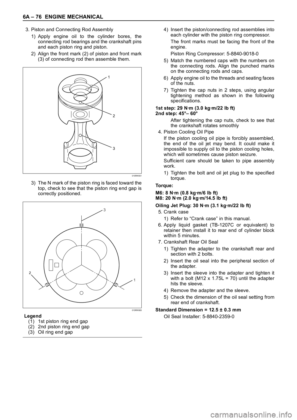
2) Align the front mark (2) of piston and front mark
(3) of connecting rod then assemble them.
3) The N mark of the piston ring is faced toward the
top, check to see that the piston ring end gap is
correctly positioned.
Legend
(1) 1st piston ring end gap
(2) 2nd piston ring end gap
(3) Oil ring end gap4) Insert the piston/connecting rod assemblies into
each cylinder with the piston ring compressor.
The front marks must be facing the front of the
engine.
Piston Ring Compressor: 5-8840-9018-0
5) Match the numbered caps with the numbers on
the connecting rods. Align the punched marks
on the connecting rods and caps.
6) Apply engine oil to the threads and seating faces
of the nuts.
7) Tighten the cap nuts in 2 steps, using angular
tightening method as shown in the following
specifications.
1st step: 29 Nꞏm (3.0 kgꞏm/22 lb ft)
2nd step: 45°– 60°
After tightening the cap nuts, check to see that
the crankshaft rotates smoothly
4. Piston Cooling Oil Pipe
If the piston cooling oil pipe is forcibly assembled,
the end of the oil jet may bend. It could make it
impossible to supply oil to the piston cooling holes,
which will sometimes cause piston seizure.
Sufficient care should be taken to pipe assembly
work.
1) Tighten the bolt and oil jet plug to the specified
torque.
To r q u e :
M6: 8 Nꞏm (0.8 kgꞏm/6 lb ft)
M8: 20 Nꞏm (2.0 kgꞏm/14.5 lb ft)
Oiling Jet Plug: 30 Nꞏm (3.1 kgꞏm/22 lb ft)
5. Crank case
1) Refer to “Crank case” in this manual.
6. Apply liquid gasket (TB-1207C or equivalent) to
retainer then install it to rear end of cylinder block
within 5 minutes.
7. Crankshaft Rear Oil Seal
1) Tighten the adapter to the crankshaft rear and
section with 2 bolts.
2) Insert the oil seal into the peripheral section of
the adapter.
3) Insert the sleeve into the adapter and tighten it
with a bolt (M12 x 1.75L = 70) until the adapter
hits the sleeve.
4) Remove the adapter and the sleeve.
5) Check the dimension of the oil seal setting from
rear end of crankshaft.
Standard Dimension = 12.5 ± 0.3 mm
Oil Seal Installer: 5-8840-2359-0
2
3
1
015RW051
3
1
2
015RW083
Page 5360 of 6000

ENGINE MECHANICAL 6A – 87
Legend
(1) 1st compressor ring gap
(2) 2nd compressor ring gap
(3) Oil ring gap
3) Insert the piston/connecting rod assemblies into
each cylinder with the piston ring compressor.
4) The front marks must be facing the front of the
engine.
Piston Ring Compressor : 5-8840-9018-0
7. Connecting Rod Bearing Cap
1) Apply engine oil to thread and seat of bearing
cap bolts.
2) Tighten the cap bolts in 2 steps, using angular
tightening method as shown in the following
specifications.
1st step: 29 Nꞏm (3.0 kgꞏm/22 lb ft)
2nd step: 45°– 60°
After tightening the cap bolts, check to see that
the crankshaft rotates smoothly.
8. Crank Case Assembly
1) Refer to “Crank Case” in this manual.
9. Cylinder Head Assembly
1) Refer to “Cylinder head” in this manual.
3
1
2
015RW083
Page 5378 of 6000

ENGINE COOLING 6B – 9
RADIATOR
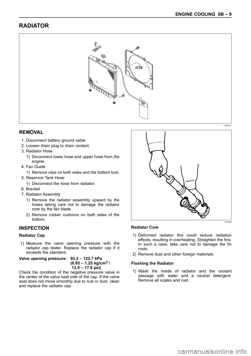
REMOVAL
1. Disconnect battery ground cable
2. Loosen drain plug to drain coolant.
3. Radiator Hose
1) Disconnect lower hose and upper hose from the
engine.
4. Fan Guide
1) Remove clips on both sides and the bottom lock.
5. Reservoir Tank Hose
1) Disconnect the hose from radiator.
6. Bracket
7. Radiator Assembly
1) Remove the radiator assembly upward by the
hoses taking care not to damage the radiator
core by the fan blade.
2) Remove rubber cushions on both sides of the
bottom.
INSPECTION
Radiator Cap
1) Measure the valve opening pressure with the
radiator cap tester. Replace the radiator cap if it
exceeds the standard.
Valve opening pressure: 93.2 – 122.7 kPa
(0.95 – 1.25 kg/cm
2/
13.5 – 17.8 psi)
Check the condition of the negative pressure valve in
the center of the valve seat side of the cap. If the valve
seat does not move smoothly due to rust or dust, clean
and replace the radiator cap.Radiator Core
1) Deformed radiator fins could reduce radiation
effects, resulting in overheating. Straighten the fins.
In such a case, take care not to damage the fin
roots.
2) Remove dust and other foreign materials.
Flushing the Radiator
1) Wash the inside of radiator and the coolant
passage with water and a neutral detergent.
Remove all scales and rust.
110RW017
110RS006
Page 5397 of 6000

6C – 16 ENGINE FUEL
INSPECTION AND REPAIR
The high pressure oil pump is made precisely,
therefore, disassembly is not recommended to repair,
only replace special parts.
Special parts
1. Reservoir
2. Fuel pump assembly
3. Bearing
4. Oil Rail Pressure Control Valve
5. High pressure oil pump
6. Repair kit
INSTALLATION
1. Set O-ring to high pressure oil pump assembly.
Install the pump assembly into the rear of timing
gear case.
Tighten nut to specified torque.
Torque: 20 Nꞏm (2.0 kgꞏm/14.5 lb ft)
Legend
(1) O-ring
(2) High Pressure Oil Pump Assembly
(3) Nuts
(4) O-ring
2. Tighten high pressure oil pump assembly bracket
together with two way valve bracket.
Torque: 27 Nꞏm (2.8 kgꞏm/20.2 lb ft)Legend
(1) High Pressure Oil Pump Assembly
(2) Nut
(3) Two Way Valve Bracket
(4) Bolt
3. Install the pump gear to align timing mark with idle
gear A.
Tighten high pressure pump gear fixing bolt to the
specified torque.
Apply engine oil to thread and seat of bolt.
Torque: 75 Nꞏm (7.6 kgꞏm/55 lb ft)
Legend
(1) O-ring
(2) Pump Gear
(3) Bolt
(4) Timing Mark
1
2
43
040RW007
2
3
4 1
040RW006
4
GEAR:O/PUMP
IDLE GEAR A
1
2
3
040RW005
Page 5605 of 6000

6E–176
4JX1–TC ENGINE DRIVEABILITY AND EMISSIONS
Symptom Diagnosis
Preliminary Checks
Before using this section, perform the “On–Board
Diagnostic (OBD) System Check” and verify all of the
following items:
The powertrain control module (ECM) and
malfunction indicator lamp (MIL) (CHECK ENGINE
lamp) are operating correctly.
There are no DTC(s) stored.
Tech–2 data is within normal operating range. Refer
to
Typical Scan Data Values.
Verify the customer complaint and locate the correct
symptom in the table of contents. Perform the
procedure included in the symptom chart.
Visual/Physical Check
Several of the symptom procedures call for a careful
visual/physical check. This can lead to correcting a
problem without further checks and can save valuable
time.
This check should include the following items:
ECM grounds for cleanliness, tightness and proper
location.
Vacuum hoses for splits, kinks, and proper
connections, as shown on the “Vehicle Emission
Control Information” label. Check thoroughly for any
type of leak or restriction.
Air intake ducts for collapsed or damaged areas.
Injector wires for cracking, hardness, and carbon
tracking.
Wiring for proper connections, pinches and cuts.
Intermittents
IMPORTANT:An intermittent problem may or may not
turn on the malfunction indicator lamp (MIL) or store a
DTC. DO NOT use the Diagnostic Trouble Code (DTC)
charts for intermittent problems. The fault must be
present to locate the problem.
Most intermittent problems are caused by faulty electrical
connections or wiring. Perform a careful visual/physical
check for the following conditions:
Poor mating of the connector halves or a terminal not
fully seated in the connector (backed out).
Improperly formed or damaged terminal.
All connector terminals in the problem circuit should
be carefully checked for proper contact tension.
Poor terminal–to–wire connection. This requires
removing the terminal from the connector body to
check.
Road test the vehicle with a Digital Multimeter
(5-8840-0285-0) connected to a suspected circuit. An
abnormal voltage when the malfunction occurs is a good
indication that there is a fault in the circuit being
monitored.
Use a scan tool to help detect intermittent conditions. The
scan tools have several features that can be used to
locate an intermittent condition. Use the following feature
to find intermittent faults:
Using a Tech–2 “Freeze Frame” buffer or “Failure
Records” buffer can aid in locating an intermittent
condition. Review and record the information in the
freeze frame or failure record associated with the
intermittent DTC being diagnosed. The vehicle can
be driven within the conditions that were present
when the DTC originally set.
To check for loss of diagnostic code memory, disconnect
the MAP sensor and idle the engine until the MIL (CHECK
ENGINE lamp) comes on. DTC P0107 should be stored
and kept in memory when the ignition is turned “OFF.” If
not, the ECM is faulty. When this test is completed, make
sure that you clear the DTC P0107 from memory.
An intermittent MIL (CHECK ENGINE lamp) with no
stored DTC may be caused by the following:
MIL (CHECK ENGINE lamp) wire to ECM shorted to
ground.
Poor ECM grounds. Refer to the ECM wiring
diagrams.
Check for improper installation of electrical options such
as lights, cellular phones, etc.
Check for an open diode across the A/C compressor
clutch and check for other open diodes (refer to wiring
diagrams in
Electrical Diagnosis).
If problem has not been found, refer to
ECM Connector
Symptom
tables.
Page 5635 of 6000

6E–206
4JX1–TC ENGINE DRIVEABILITY AND EMISSIONS
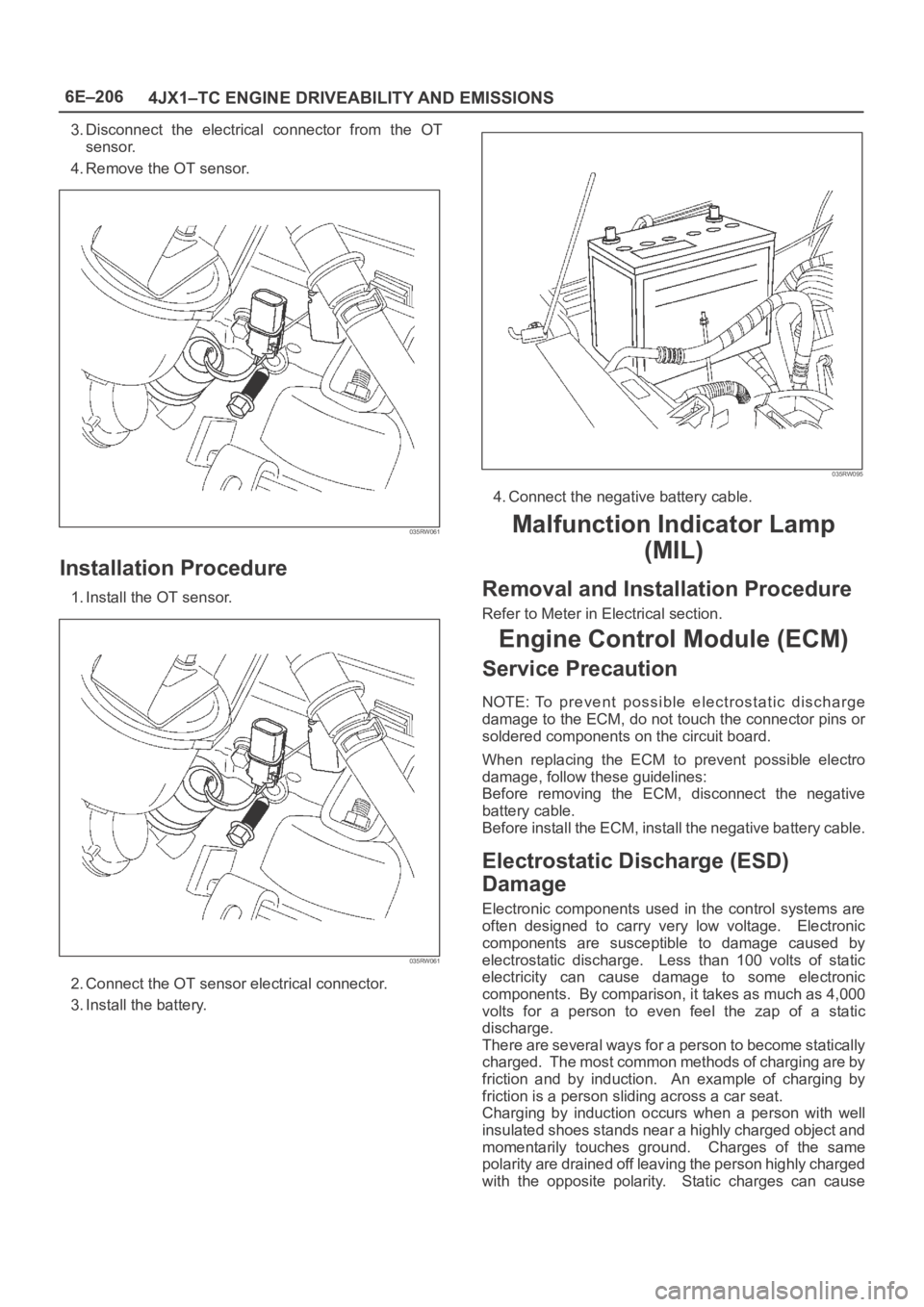
3. Disconnect the electrical connector from the OT
sensor.
4. Remove the OT sensor.
035RW061
Installation Procedure
1. Install the OT sensor.
035RW061
2. Connect the OT sensor electrical connector.
3. Install the battery.
035RW095
4. Connect the negative battery cable.
Malfunction Indicator Lamp
(MIL)
Removal and Installation Procedure
Refer to Meter in Electrical section.
Engine Control Module (ECM)
Service Precaution
NOTE: To prevent possible electrostatic discharge
damage to the ECM, do not touch the connector pins or
soldered components on the circuit board.
When replacing the ECM to prevent possible electro
damage, follow these guidelines:
Before removing the ECM, disconnect the negative
battery cable.
Before install the ECM, install the negative battery cable.
Electrostatic Discharge (ESD)
Damage
Electronic components used in the control systems are
often designed to carry very low voltage. Electronic
components are susceptible to damage caused by
electrostatic discharge. Less than 100 volts of static
electricity can cause damage to some electronic
components. By comparison, it takes as much as 4,000
volts for a person to even feel the zap of a static
discharge.
There are several ways for a person to become statically
charged. The most common methods of charging are by
friction and by induction. An example of charging by
friction is a person sliding across a car seat.
Charging by induction occurs when a person with well
insulated shoes stands near a highly charged object and
momentarily touches ground. Charges of the same
polarity are drained off leaving the person highly charged
with the opposite polarity. Static charges can cause
Page 5636 of 6000

6E–207 4JX1–TC ENGINE DRIVEABILITY AND EMISSIONS
damage, therefore, it is important to use care when
handling and testing electronic components.
NOTE: To prevent possible Electrostatic Discharge
damage, follow these guidelines:
Do not touch the control module connector pins or
soldered components on the control module circuit
board.
Do not open the replacement part package until the
part is ready to be installed.
Before removing the part from the package, ground
the package to a known good ground on the vehicle.
If the part has been handled while sliding across the
seat, or while sitting down from a standing position, or
while walking a distance, touch a known good ground
before installing the part.
NOTE: To prevent internal ECM damage, the ignition
must be in the “OFF” position in order to disconnect or
reconnect power to the ECM (for example: battery cable,
ECM pigtail, ECM fuse, jumper cables, etc.).
IMPORTANT:When replacing the production ECM
with a service ECM, it is important to transfer the
broadcast code and production ECM number to the
service ECM label. This will allow positive identification of
ECM parts throughout the service life of the vehicle. Do
not record this information on the metal ECM cover.
IMPORTANT:The ignition should always be in the
“OFF” position in order to install or remove the ECM
connectors.
Service of the ECM should normally consist of either re-
placement of the ECM. If the diagnostic procedures call
for the ECM to be replaced, the ECM should be checked
first to ensure it is the correct part. If it is, remove the
faulty ECM and install the new service ECM.
DTC P0601 indicates the check sum error.
Removal Procedure
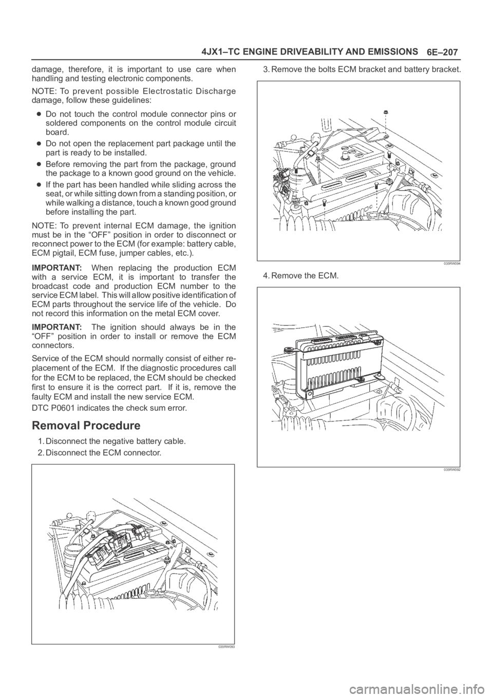
1. Disconnect the negative battery cable.
2. Disconnect the ECM connector.
035RW093
3. Remove the bolts ECM bracket and battery bracket.
035RW094
4. Remove the ECM.
035RW092
Page 5652 of 6000

6E–223 4JX1–TC ENGINE DRIVEABILITY AND EMISSIONS
Weather-Pack Connector
To o l s R e q u i r e d
5-8840-0388-0 Weather-Pack II Terminal Remover
Removal Procedure
A Weather-Pack connector can be identified by a rubber
seal at the rear of the connector. This engine room
connector protects against moisture and dirt, which could
from oxidation and deposits on the terminals. This
protection is important, because of the low voltage and
the low amperage found in the electronic systems.
1. Open the secondary lock hinge on the connector.
070
2. Use tool 5-8840-0388-0 or the equivalent to remove
the pin and the sleeve terminals. Push on
5-8840-0388-0 to release.
NOTE: Do the use an ordinary pick or the terminal may
be bent or deformed. Unlike standard blade terminals,
these terminals cannot be straightened after they have
been improperly bent.
071
3. Cut the wire immediately behind the cable seal.
072
Installation Procedure
Make certain the connectors are properly seated and all
of the sealing rings are in place when you reconnect the
leads. The secondary lock hinge provides a backup
locking feature for the connector. The secondary lock
hinge is used for added reliability. This flap should retain
the terminals even if the small terminal lock tangs are not
positioned properly.
Do not replace the Weather-Pack connections with
standard connections. Read the instructions provided
with the Weather-Pack connector and terminal packages.
1. Replace the terminal.
2. Slip the new seal onto the wire.
3. Strip 5 mm (0.2”) of insulation from the wire.
4. Crimp the terminal over the wire and the seal.
073
Page 5653 of 6000

6E–224
4JX1–TC ENGINE DRIVEABILITY AND EMISSIONS
5. Push the terminal and the connector to engage the
locking tangs.
070
6. Close the secondary locking hinge.
Com-Pack III
General Information
The Com-Pack III terminal looks similar to some
Weather-Pack terminals. This terminal is not sealed and
is used where resistance to the environment is not
required. Use the standard method when repairing a
terminal. Do not use the Weather-Pack terminal tool
5-8840-0388-0 or equivalent. These will damage the
terminals.
Metri-Pack
To o l s R e q u i r e d
5-8840-0632-0 Terminal Remover
Removal Procedure
S o m e c o n n e c t o r s u s e t e r m i n a l s c a l l e d M e t r i - P a c k S e r i e s
150. These may be used at the engine coolant
temperature (ECT) sensor.
1. Slide the seal (1) back on the wire.2. Insert the 5-8840-0632-0 tool or equivalent (3) in
order to release the terminal locking tang (2).
060
3. Push the wire and the terminal out through the
connector. If you reuse the terminal, reshape the
locking tang.
Installation Procedure
Metri-Pack terminals are also referred to as “pull-to-seat”
terminals.
1. In order to install a terminal on a wire, the wire must be
inserted through the seal (2) and through the
connector (3).
2. The terminal (1) is then crimped onto the wire.
061
3. Then the terminal is pulled back into the connector to
seat it in place.
Page 5656 of 6000

6E–227 4JX1–TC ENGINE DRIVEABILITY AND EMISSIONS
QOS
Diagnostics
– Malfunction Indicator Lamp (Service Engine
Soon lamp)
– Data Link Connector (DLC)
– Data Output
ECM Service Precautions
The ECM is designed to withstand normal current draws
associated with vehicle operation. Avoid overloading any
circuit. When testing for opens and shorts, do not ground
or apply voltage to any of the ECM’s circuits unless
instructed to do so. These circuits should only be tested
using digital voltmeter. The ECM should remain
connected to the ECM or to a recommended breakout
box.
Intake Throttle Position (ITP) Sensor
ITP sensor is a potentiometer type and installed to the
intake throttle valve body. A voltage of 5V is applied
constantly from ECM to ITP sensor thereby to determine
by change in voltage the opening of the intake throttle
valve during warming up.
Transmission Range Switch
IMPORTANT:The vehicle should not be driven with the
transmission range switch disconnected; idle quality will
be affected.
The four inputs from the transmission range switch
indicate to the ECM which position is selected by the
transmission selector lever.
For more information on the transmission on the
transmission range switch, refer to
Automatic
Tr a n s m i s s i o n
.
Accelerator Position Sensor (AP)
AP sensor is a potentiometer type and installed to
accelerator pedal bracket. A voltage of 5V constantly
applied from ECM to the sensor thereby to determine the
accelerator pedaling angle by change in voltage. Further,
this sensor is provided with an accelerator switch, which
is set off only when the accelerator pedal is stepped on.
Aftermarket Electrical and Vacuum
Equipment
Aftermarket (add-on) electrical and vacuum equipment is
defined as any equipment which connects to the vehicle’s
electrical or vacuum systems that is installed on a vehicle
after it leaves the factory. No allowances have been
made in the vehicle design for this type of equipment.
NOTE: No add-on vacuum equipment should be added
to this vehicle.
NOTE: Add-on electrical equipment must only be
connected to the vehicle’s electrical system at the battery
(power and ground).
Add-on electrical equipment, even when installed to
these guidelines, may still cause the powertrain system to
malfunction. This may also include equipment not
connected to the vehicle electrical system such asportable telephones and radios. Therefore, the first step
in diagnosing any powertrain problem is to eliminate all
aftermarket electrical equipment from the vehicle. After
this is done, if the problem still exists, it may be diagnosed
in the normal manner.
Electrostatic Discharge Damage
Electronic components used in the ECM are often
designed to carry very low voltage. Electronic
components are susceptible to damage caused by
electrostatic discharge. Less than 100 volts of static
electricity can cause damage to some electronic
components. By comparison, it takes as much as 4000
volts for a person to feel even the zap of a static
discharge.
TS23793
There are several ways for a person to become statically
charged. The most common methods of charging are by
friction and induction.
An example of charging by friction is a person sliding
across a vehicle seat.
Charge by induction occurs when a person with well
insulated shoes stands near a highly charged object
and momentary touches ground. Charges of the
same polarity are drained off leaving the person
highly charged with the opposite polarity. Static
charges can cause damage, therefore it is important
to use care when handling and testing electronic
components.
NOTE: To prevent possible electrostatic discharge
damage, follow these guidelines:
Do not touch the ECM connector pins or soldered
components on the ECM circuit board.
Do not open the replacement part package until the
part is ready to be installed.
Before removing the part from the package, ground
the package to a known good ground on the vehicle.
If the part has been handled while sliding across the
seat, while sitting down from a standing position, or
while walking a distance, touch a known good ground
before installing the part.