compression ratio OPEL FRONTERA 1998 Owner's Manual
[x] Cancel search | Manufacturer: OPEL, Model Year: 1998, Model line: FRONTERA, Model: OPEL FRONTERA 1998Pages: 6000, PDF Size: 97 MB
Page 4586 of 6000

6A–90
ENGINE MECHANICAL
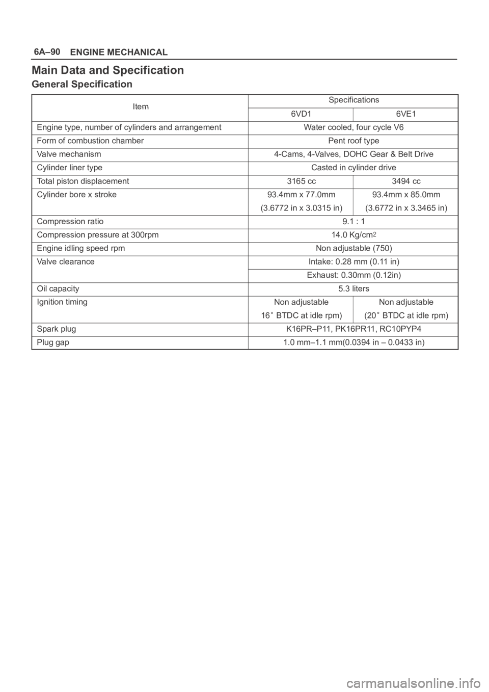
Main Data and Specification
General Specification
ItemSpecificationsItem6VD16VE1
Engine type, number of cylinders and arrangementWater cooled, four cycle V6
Form of combustion chamberPent roof type
Valve mechanism4-Cams, 4-Valves, DOHC Gear & Belt Drive
Cylinder liner typeCasted in cylinder drive
Total piston displacement3165 cc3494 cc
Cylinder bore x stroke93.4mm x 77.0mm93.4mm x 85.0mm
(3.6772 in x 3.0315 in)(3.6772 in x 3.3465 in)
Compression ratio9.1 : 1
Compression pressure at 300rpm14.0 Kg/cm
Engine idling speed rpmNon adjustable (750)
Valve clearanceIntake: 0.28 mm (0.11 in)
Exhaust: 0.30mm (0.12in)
Oil capacity5.3 liters
Ignition timingNon adjustableNon adjustable
16 BTDC at idle rpm)(20 BTDC at idle rpm)
Spark plugK16PR–P11, PK16PR11, RC10PYP4
Plug gap1.0 mm–1.1 mm(0.0394 in – 0.0433 in)
Page 4921 of 6000

6E–264
ENGINE DRIVEABILITY AND EMISSIONS
Hard Start Symptom
StepNo Ye s Va l u e ( s ) Action
121. Remove spark plugs. Check for wet plugs, cracks,
wear, improper gap, burned electrodes, or heavy
deposits. Refer to
Electronic Ignition System.
NOTE: If spark plugs are gas or oil fouled, the cause of
the fouling must be determined before replacing the
spark plugs.
2. If a problem is found, repair as necessary.
Was a problem found?
—Verify repairGo to Step 13
131. Check for a loose ignition coil ground.
Refer to
Electronic Ignition System.
2. If a problem is found, repair as necessary.
Was a problem found?
—Verify repairGo to Step 14
141. Remove the ignition coils and check the ignition
coils for cracks or carbon tracking.
2. If a problem is found, replace affected coil(s) as
necessary.
Was a problem found?
—Verify repairGo to Step 15
151. Check IAC operation. Perform the procedure in the
DTC P0506, Step 6 diagnostic table.
2. If a problem is found, repair as necessary.
Was a problem found?
—Verify repairGo to Step 16
161. Check for the following engine mechanical
problems (refer to
Engine Mechanical):
Low compression
Leaking cylinder head gaskets
Worn or incorrect camshaft
Camshaft drive belt slipped or stripped
2. If a problem is found, repair as necessary.
Was a problem found?
—Verify repairGo to Step 17
171. Review all diagnostic procedures within this table.
2. If all procedures have been completed and no
malfunctions have been found, review/inspect the
following:
Visual/physical inspection
Te c h 2 d a t a
Freeze Frame data/Failure Records buffer
All electrical connections within a suspected
circuit and/or system.
3. If a problem is found, repair as necessary.
Was a problem found?
—Verify repair
Contact
Te c h n i c a l
Assistance
Page 4926 of 6000

6E–269 ENGINE DRIVEABILITY AND EMISSIONS
Lack of Power, Sluggish or Spongy Symptom
StepNo Ye s Va l u e ( s ) Action
111. Check the PCM grounds for the cleanliness,
tightness and proper locations. Refer to the PCM
wiring diagrams in
Electrical Diagnosis.
2. If a problem is found, repair as necessary.
Was a problem found?
—Verify repairGo to Step 12
121. Check the exhaust system for possible restriction:
Inspect the exhaust system for damaged or
collapsed pipes.
Inspect the muffler for heat distress or possible
internal failure.
Check for a possible plugged three-way
catalytic converter by checking the exhaust
system back pressure. Refer to
Restricted
Exhaust System Check
.
2. If a problem is found, repair as necessary.
Was a problem found?
—Verify repairGo to Step 13
131. Check the torque converter clutch (TCC) for proper
operation. Refer to
4L30-E Transmission
Diagnosis
.
2. If a problem is found, repair as necessary.
Was a problem found?
—Verify repairGo to Step 14
141. Check for an engine mechanical problem. Check
for low compression, incorrect or worn camshaft,
loose timing belt, etc. Refer to
Engine Mechanical.
2. If a problem is found, repair as necessary.
Was a problem found?
—Verify repairGo to Step 15
151. Review all diagnostic procedures within this table.
2. If all procedures have been completed and no
malfunctions have been found, review/inspect the
following:
Visual/physical inspection
Te c h 2 d a t a
Freeze Frame data/Failure Records buffer
All electrical connections within a suspected
circuit and/or system.
3. If a problem is found, repair as necessary.
Was a problem found?
—Verify repair
Contact
Te c h n i c a l
Assistance
Page 4931 of 6000

6E–274
ENGINE DRIVEABILITY AND EMISSIONS
Rough, Unstable, or Incorrect Idle, Stalling Symptom
StepNo Ye s Va l u e ( s ) Action
171. Check ignition coils for cracks or carbon tracking.
2. If a problem is found, repair as necessary.
Was a problem found?
—Verify repairGo to Step 18
18Using Tech 2, monitor the throttle position (TP) angle
with the engine idling.
Is the TP angle at the specified value and steady?
0%Go to Step 19
Refer to DTC
P0123
for
further
diagnosis
191. Check the positive crankcase ventilation (PCV)
valve for proper operation. Refer to
Crankcase
Ventilation System
.
2. If a problem is found, repair as necessary.
Was a problem found?
—Verify repairGo to Step 20
201. Check the transmission range switch circuit. Use
Tech 2 and be sure Tech 2 indicates that the vehicle
is in drive with the gear selector in drive or overdrive.
2. If a problem is found, diagnose and repair the
transmission range switch as necessary (refer to
4L30-E Automatic Transmission Diagnosis).
Was a problem found?
—Verify repairGo to Step 21
211. Check for the following engine mechanical items.
Refer to
Engine Mechanical for diagnosis
procedures:
EGR valve mounted backward. Compare with
a known-good vehicle.
Low compression
Sticking or leaking valves
Worn camshaft lobe(s)
Camshaft drive belt slipped or stripped
Incorrect valve timing
Worn rocker arms
Broken valve springs
2. If a problem is found, repair as necessary.
Was a problem found?
—Verify repairGo to Step 22
221. Check for faulty motor mounts. Refer to Engine
Mechanical
for inspection of mounts.
2. If a problem is found, repair as necessary.
Was a problem found?
—Verify repairGo to Step 23
231. Review all diagnostic procedures within this table.
2. If all procedures have been completed and no
malfunctions have been found, review/inspect the
following:
Visual/physical inspection
Te c h 2 d a t a
Freeze Frame data/Failure Records buffer
All electrical connections within a suspected
circuit and/or system.
3. If a problem is found, repair as necessary.
Was a problem found?
—Verify repair
Contact
Te c h n i c a l
Assistance
Page 4933 of 6000

6E–276
ENGINE DRIVEABILITY AND EMISSIONS
Poor Fuel Economy Symptom
StepNo Ye s Va l u e ( s ) Action
101. Check for an incorrect or faulty engine thermostat.
Refer to
Engine Cooling.
2. If a problem is found, repair as necessary.
Was a problem found?
—Verify repairGo to Step 11
111. Check for low engine compression. Refer to Engine
Mechanical
.
2. If a problem is found, repair as necessary.
Was a problem found?
—Verify repairGo to Step 12
121. Check the TCC operation. Refer to 4L30-E
Transmission Diagnosis
.
2. If a problem is found, repair as necessary.
Was a problem found?
—Verify repairGo to Step 13
131. Check the exhaust system for possible restriction:
Inspect the exhaust system for damaged or
collapsed pipes.
Inspect the muffler for heat distress or possible
internal failure.
Check for a possible plugged three-way
catalytic converter by checking the exhaust
system back pressure. Refer to
Restricted
Exhaust System Check
.
2. If a problem is found, repair as necessary.
Was a problem found?
—Verify repairGo to Step 14
14Check for proper calibration of the speedometer.
Does the speed indicated on the speedometer closely
match the vehicle speed displayed on Tech 2?
—Go to Step 16Go to Step 15
15Diagnose and repair an inaccurate speedometer
condition as necessary. Refer to
Vehicle Speed
Sensor
in Electrical Diagnosis.
Was a problem found?
—Verify repair—
161. Check the air intake system and the crankcase for
air leaks. Refer to
Air Intake System and
Crankcase Ventilation System.
2. If a problem is found, repair as necessary.
Was a problem found?
—Verify repairGo to Step 17
171. Review all diagnostic procedures within this table.
2. When all procedures have been completed and no
malfunctions have been found, review/inspect the
following:
Visual/physical inspection
Te c h 2 d a t a
Freeze Frame data/Failure Records buffer
All connections within a suspected circuit
and/or system.
3. If a problem is found, repair as necessary.
Was a problem found?
—Verify repairGo to Step 18
18Perform the procedure in Fuel System Pressure Test.
Was the fuel pressure normal?
—
Contact
Te c h n i c a l
Assistance
Verify repair
Page 4941 of 6000

6E–284
ENGINE DRIVEABILITY AND EMISSIONS
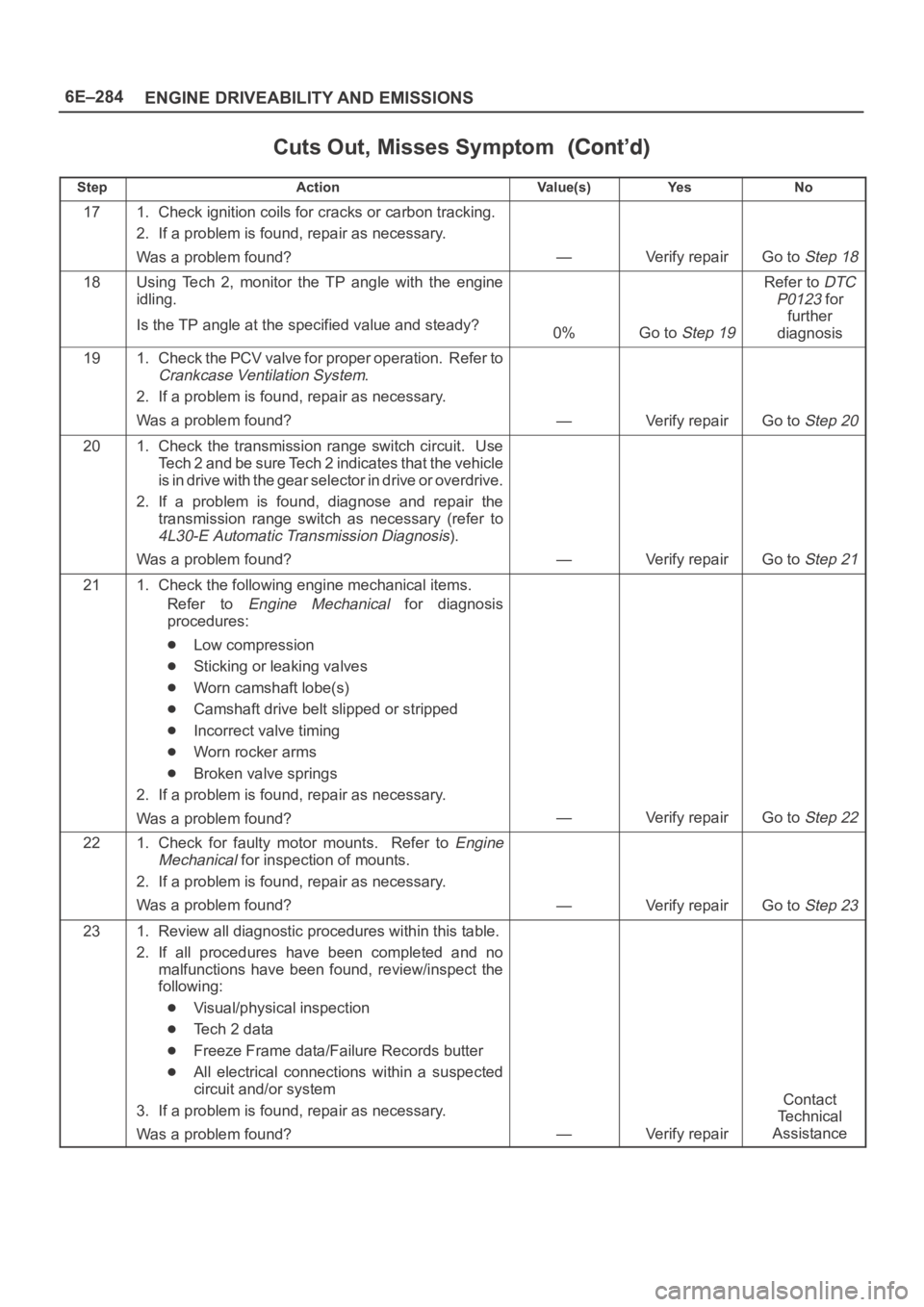
Cuts Out, Misses Symptom
StepNo Ye s Va l u e ( s ) Action
171. Check ignition coils for cracks or carbon tracking.
2. If a problem is found, repair as necessary.
Was a problem found?
—Verify repairGo to Step 18
18Using Tech 2, monitor the TP angle with the engine
idling.
Is the TP angle at the specified value and steady?
0%Go to Step 19
Refer to DTC
P0123
for
further
diagnosis
191. Check the PCV valve for proper operation. Refer to
Crankcase Ventilation System.
2. If a problem is found, repair as necessary.
Was a problem found?
—Verify repairGo to Step 20
201. Check the transmission range switch circuit. Use
Tech 2 and be sure Tech 2 indicates that the vehicle
is in drive with the gear selector in drive or overdrive.
2. If a problem is found, diagnose and repair the
transmission range switch as necessary (refer to
4L30-E Automatic Transmission Diagnosis).
Was a problem found?
—Verify repairGo to Step 21
211. Check the following engine mechanical items.
Refer to
Engine Mechanical for diagnosis
procedures:
Low compression
Sticking or leaking valves
Worn camshaft lobe(s)
Camshaft drive belt slipped or stripped
Incorrect valve timing
Worn rocker arms
Broken valve springs
2. If a problem is found, repair as necessary.
Was a problem found?
—Verify repairGo to Step 22
221. Check for faulty motor mounts. Refer to Engine
Mechanical
for inspection of mounts.
2. If a problem is found, repair as necessary.
Was a problem found?
—Verify repairGo to Step 23
231. Review all diagnostic procedures within this table.
2. If all procedures have been completed and no
malfunctions have been found, review/inspect the
following:
Visual/physical inspection
Te c h 2 d a t a
Freeze Frame data/Failure Records butter
All electrical connections within a suspected
circuit and/or system
3. If a problem is found, repair as necessary.
Was a problem found?
—Verify repair
Contact
Te c h n i c a l
Assistance
Page 5275 of 6000

6A – 2 ENGINE MECHANICAL
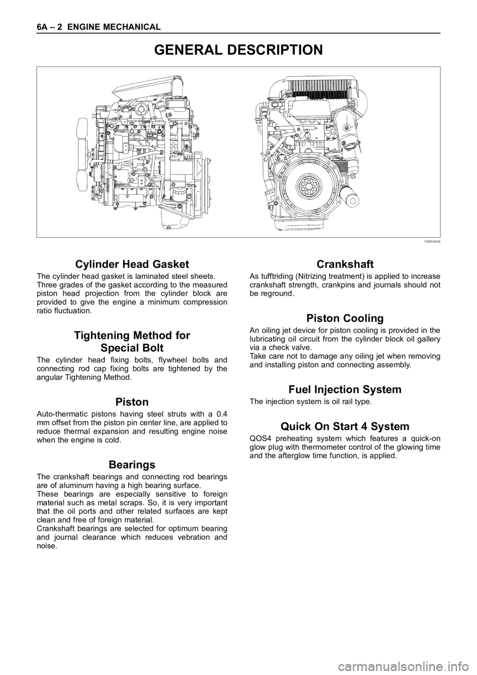
GENERAL DESCRIPTION
Cylinder Head Gasket
The cylinder head gasket is laminated steel sheets.
Three grades of the gasket according to the measured
piston head projection from the cylinder block are
provided to give the engine a minimum compression
ratio fluctuation.
Tightening Method for
Special Bolt
The cylinder head fixing bolts, flywheel bolts and
connecting rod cap fixing bolts are tightened by the
angular Tightening Method.
Piston
Auto-thermatic pistons having steel struts with a 0.4
mm offset from the piston pin center line, are applied to
reduce thermal expansion and resulting engine noise
when the engine is cold.
Bearings
The crankshaft bearings and connecting rod bearings
are of aluminum having a high bearing surface.
These bearings are especially sensitive to foreign
material such as metal scraps. So, it is very important
that the oil ports and other related surfaces are kept
clean and free of foreign material.
Crankshaft bearings are selected for optimum bearing
and journal clearance which reduces vebration and
noise.
Crankshaft
As tufftriding (Nitrizing treatment) is applied to increase
crankshaft strength, crankpins and journals should not
be reground.
Piston Cooling
An oiling jet device for piston cooling is provided in the
lubricating oil circuit from the cylinder block oil gallery
via a check valve.
Take care not to damage any oiling jet when removing
and installing piston and connecting assembly.
Fuel Injection System
The injection system is oil rail type.
Quick On Start 4 System
QOS4 preheating system which features a quick-on
glow plug with thermometer control of the glowing time
and the afterglow time function, is applied.
F06RW048
Page 5276 of 6000

ENGINE MECHANICAL 6A – 3
SERVICE INFORMATION
MAIN DATA AND SPECIFICATION
Engine type Diesel, four cycle water cooled inline
Camshaft type DOHC
Number of cylinders 4
Bore x stroke (mm) 95.4 x 104.9
Total piston displacement (cc) 2999
Compression ratio (to 1) 19.0
Engine weight (dry) N (kg/lb) 2492 (254/560) (A/T)
2649 (270/593) (M/T)
Engine idling speed (Reference) RPM 720
Compression pressure kpa (kg/cm
2/psi)-rpm 3000 (31/440)-200
Firing order 1–3–4–2
VALVE SYSTEM
Intake valves open at: B.T.D.C. 3°
close at: A.B.D.C. 57.6°
Exhaust valves open at: B.B.D.C. 56.5°
close at: A.T.D.C. 5°
Valve clearance at cold mm (in)
intake: 0.15 (0.006)
exhaust: 0.25 (0.01)
Oil filter Full flow and bypass combined type
Oil capacity (Original factory fill or rebuilt engine) 9.0 liters (7.9 US quarts)
Oil capacity (Service change)
with filter change 6.0 liters (6.3 US quarts)
without filter change 5.0 liters (5.3 US quarts)
Oil cooler Water cooled type
Inter cooler Air cooled type
Turbocharger method
Control method Wastegate control
Lubrication Pressurized control
Cooling method Coolant cooled
Page 5297 of 6000

6A – 24 ENGINE MECHANICAL
Illustration Tool No. Tool Name
SPECIAL TOOLS
5-8840-2590-0 Valve Clearance Adjusting Tool
5-8840-2592-0 Camshaft Stopper
5-8840-2591-0 Camshaft Gear Tool
5-8840-2675-0
5-8531-7002-0Compression Gauge
Adapter: Compression Gauge
5-8840-2153-0 Seal Cutter
kg /cm20 10
7060 20 5030 40
F06RW056
F06RV037
901LX057
901LX056 F06RW057
901RT042
Page 5336 of 6000

ENGINE MECHANICAL 6A – 63
VALVE CLEARANCE ADJUSTMENT
NOTE:
1. Valve clearance should be inspected and adjusted
while the engine is cool.
2. The tightening of the camshaft bearing cap and
camshaft carrier assembly should be checked
before inspecting and adjusting valve clearance.
INSPECTION
1. Remove cylinder head noise insulator cover and
cylinder head cover.
Refer to “Cylinder Head” in this manual.
2. Disconnect all harness connecters of the injector
and remove harness assembly.
3. Drain oil from oil rail assembly.
4. Remove injector clamp nuts and fixing bolts to take
out injector assembly.
5. Loosen oil rail bolts, remove oil rail assembly.
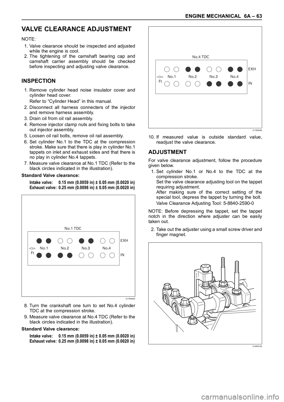
6. Set cylinder No.1 to the TDC at the compression
stroke. Make sure that there is play in cylinder No.1
tappets on inlet and exhaust sides and that there is
no play in cylinder No.4 tappets.
7. Measure valve clearance at No.1 TDC (Refer to the
black circles indicated in the illustration).
Standard Valve clearance:
Intake valve: 0.15 mm (0.0059 in) ± 0.05 mm (0.0020 in)
Exhaust valve: 0.25 mm (0.0098 in) ± 0.05 mm (0.0020 in)
8. Turn the crankshaft one turn to set No.4 cylinder
TDC at the compression stroke.
9. Measure valve clearance at No.4 TDC (Refer to the
black circles indicated in the illustration).
Standard Valve clearance:
Intake valve: 0.15 mm (0.0059 in) ± 0.05 mm (0.0020 in)
Exhaust valve: 0.25 mm (0.0098 in) ± 0.05 mm (0.0020 in)
10. If measured value is outside standard value,
readjust the valve clearance.
ADJUSTMENT
For valve clearance adjustment, follow the procedure
given below.
1. Set cylinder No.1 or No.4 to the TDC at the
compression stroke.
Set the valve clearance adjusting tool on the tappet
requiring adjustment.
After making sure of the correct setting of the
special tool, depress the tappet by turning the bolt.
Valve Clearance Adjusting Tool: 5-8840-2590-0
NOTE: Before depressing the tappet, set the tappet
notch in the direction where adjuster can be easily
taken out.
2. Take out the adjuster using a small screw driver and
finger magnet.
011RW045
011RW046
014RW150