radiator OPEL FRONTERA 1998 Owner's Manual
[x] Cancel search | Manufacturer: OPEL, Model Year: 1998, Model line: FRONTERA, Model: OPEL FRONTERA 1998Pages: 6000, PDF Size: 97 MB
Page 1064 of 6000

ENGINE COOLING6B–11
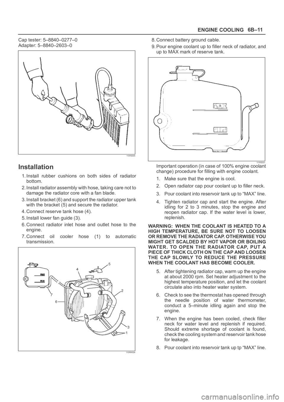
Cap tester: 5–8840–0277–0
Adapter: 5–8840–2603–0
110RS005
Installation
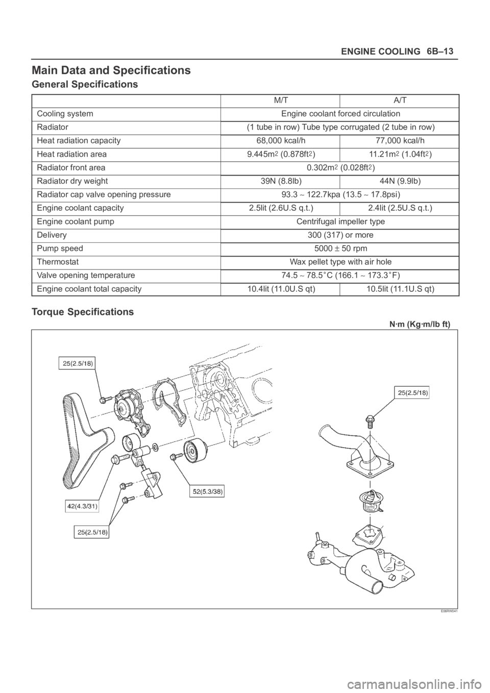
1. Install rubber cushions on both sides of radiator
bottom.
2. Install radiator assembly with hose, taking care not to
damage the radiator core with a fan blade.
3. Install bracket (6) and support the radiator upper tank
with the bracket (5) and secure the radiator.
4. Connect reserve tank hose (4).
5. Install lower fan guide (3).
6. Connect radiator inlet hose and outlet hose to the
engine.
7. Connect oil cooler hose (1) to automatic
transmission.
110RW004
8. Connect battery ground cable.
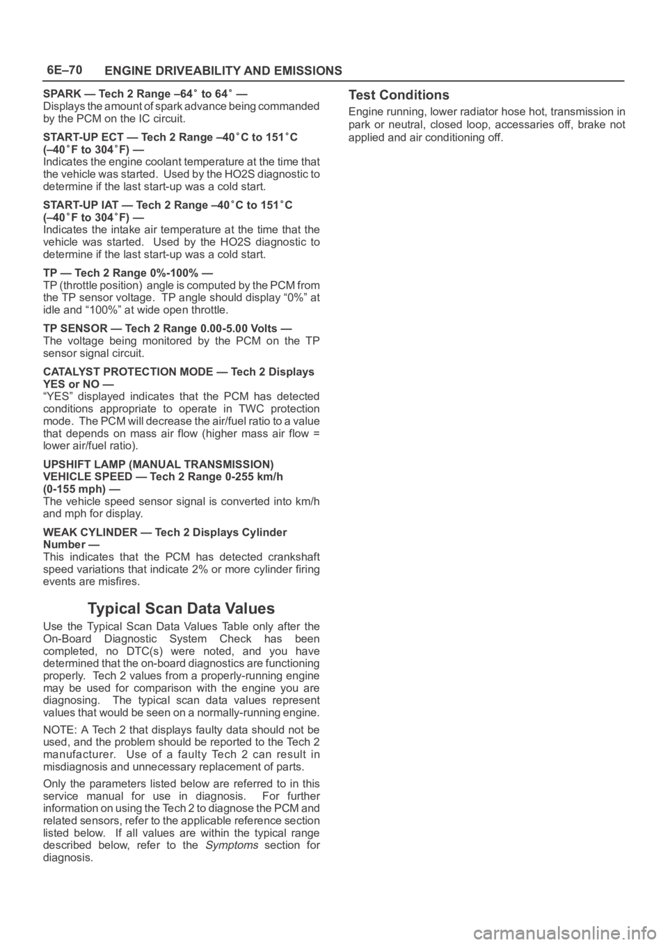
9. Pour engine coolant up to filler neck of radiator, and
up to MAX mark of reserve tank.
111 R S 0 0 1Important operation (in case of 100% engine coolant
change) procedure for filling with engine coolant.
1. Make sure that the engine is cool.
2. Open radiator cap pour coolant up to filler neck.
3. Pour coolant into reservoir tank up to “MAX” line.
4. Tighten radiator cap and start the engine. After
idling for 2 to 3 minutes, stop the engine and
reopen radiator cap. If the water level is lower,
replenish.
WARNING: WHEN THE COOLANT IS HEATED TO A
HIGH TEMPERATURE, BE SURE NOT TO LOOSEN
OR REMOVE THE RADIATOR CAP. OTHERWISE YOU
MIGHT GET SCALDED BY HOT VAPOR OR BOILING
WATER. TO OPEN THE RADIATOR CAP, PUT A
PIECE OF THICK CLOTH ON THE CAP AND LOOSEN
THE CAP SLOWLY TO REDUCE THE PRESSURE
WHEN THE COOLANT HAS BECOME COOLER.
5. After tightening radiator cap, warm up the engine
at about 2000 rpm. Set heater adjustment to the
highest temperature position, and let the coolant
circulate also into heater water system.
6. Check to see the thermostat has opened through
the needle position of water thermometer,
conduct a 5–minute idling again and stop the
engine.
7. When the engine has been cooled, check filler
neck for water level and replenish if required.
Should extreme shortage of coolant is found,
check the cooling system and reservoir tank hose
for leakage.
8. Pour coolant into reservoir tank up tp “MAX” line.
Page 1066 of 6000

ENGINE COOLING6B–13
Main Data and Specifications
General Specifications
M/TA/T
Cooling systemEngine coolant forced circulation
Radiator(1 tube in row) Tube type corrugated (2 tube in row)
Heat radiation capacity68,000 kcal/h77,000 kcal/h
Heat radiation area9.445m (0.878ft)11 . 2 1 m (1.04ft)
Radiator front area0.302m (0.028ft)
Radiator dry weight39N (8.8lb)44N (9.9lb)
Radiator cap valve opening pressure93.3 122.7kpa (13.5 17.8psi)
Engine coolant capacity2.5lit (2.6U.S q.t.)2.4lit (2.5U.S q.t.)
Engine coolant pumpCentrifugal impeller type
Delivery300 (317) or more
Pump speed5000 50 rpm
ThermostatWax pellet type with air hole
Valve opening temperature74.5 78.5C (166.1 173.3F)
Engine coolant total capacity10.4lit (11.0U.S qt)10.5lit (11.1U.S qt)
Torque Specifications
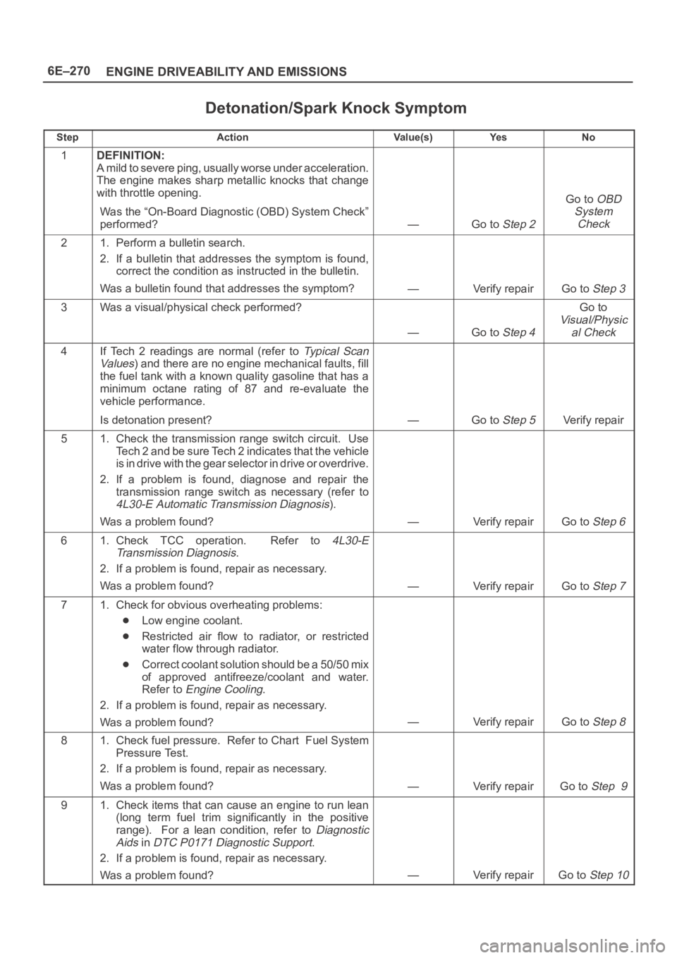
Nꞏm (Kgꞏm/lb ft)
E06RW041
Page 1067 of 6000

6B–14
ENGINE COOLING
Special Tool
ILLUSTRATIONTOOL NO.
TOOL NAME
5–8840–0277–0
(J–24460–01)
Tester; radiator cap
5–8840–2603–0
(J–33984–A)
Adapter; radiator cap
Page 1187 of 6000

6E–70
ENGINE DRIVEABILITY AND EMISSIONS
SPARK — Tech 2 Range –64 to 64 —
Displays the amount of spark advance being commanded
by the PCM on the IC circuit.
START-UP ECT — Tech 2 Range –40
C to 151C
(–40
F to 304F) —
Indicates the engine coolant temperature at the time that
the vehicle was started. Used by the HO2S diagnostic to
determine if the last start-up was a cold start.
START-UP IAT — Tech 2 Range –40
C to 151C
(–40
F to 304F) —
Indicates the intake air temperature at the time that the
vehicle was started. Used by the HO2S diagnostic to
determine if the last start-up was a cold start.
TP — Tech 2 Range 0%-100% —
TP (throttle position) angle is computed by the PCM from
the TP sensor voltage. TP angle should display “0%” at
idle and “100%” at wide open throttle.
TP SENSOR — Tech 2 Range 0.00-5.00 Volts —
The voltage being monitored by the PCM on the TP
sensor signal circuit.
CATALYST PROTECTION MODE — Tech 2 Displays
YES or NO —
“YES” displayed indicates that the PCM has detected
conditions appropriate to operate in TWC protection
mode. The PCM will decrease the air/fuel ratio to a value
that depends on mass air flow (higher mass air flow =
lower air/fuel ratio).
UPSHIFT LAMP (MANUAL TRANSMISSION)
VEHICLE SPEED — Tech 2 Range 0-255 km/h
(0-155 mph) —
The vehicle speed sensor signal is converted into km/h
and mph for display.
WEAK CYLINDER — Tech 2 Displays Cylinder
Number —
This indicates that the PCM has detected crankshaft
speed variations that indicate 2% or more cylinder firing
events are misfires.
Typical Scan Data Values
Use the Typical Scan Data Values Table only after the
On-Board Diagnostic System Check has been
completed, no DTC(s) were noted, and you have
determined that the on-board diagnostics are functioning
properly. Tech 2 values from a properly-running engine
may be used for comparison with the engine you are
diagnosing. The typical scan data values represent
values that would be seen on a normally-running engine.
NOTE: A Tech 2 that displays faulty data should not be
used, and the problem should be reported to the Tech 2
manufacturer. Use of a faulty Tech 2 can result in
misdiagnosis and unnecessary replacement of parts.
Only the parameters listed below are referred to in this
service manual for use in diagnosis. For further
information on using the Tech 2 to diagnose the PCM and
related sensors, refer to the applicable reference section
listed below. If all values are within the typical range
described below, refer to the
Symptoms section for
diagnosis.
Test Conditions
Engine running, lower radiator hose hot, transmission in
park or neutral, closed loop, accessaries off, brake not
applied and air conditioning off.
Page 1387 of 6000

6E–270
ENGINE DRIVEABILITY AND EMISSIONS
Detonation/Spark Knock Symptom
StepActionVa l u e ( s )Ye sNo
1DEFINITION:
A mild to severe ping, usually worse under acceleration.
The engine makes sharp metallic knocks that change
with throttle opening.
Was the “On-Board Diagnostic (OBD) System Check”
performed?
—Go to Step 2
Go to OBD
System
Check
21. Perform a bulletin search.
2. If a bulletin that addresses the symptom is found,
correct the condition as instructed in the bulletin.
Was a bulletin found that addresses the symptom?
—Verify repairGo to Step 3
3Was a visual/physical check performed?
—Go to Step 4
Go to
Visual/Physic
al Check
4If Tech 2 readings are normal (refer to Ty p i c a l S c a n
Va lu es
) and there are no engine mechanical faults, fill
the fuel tank with a known quality gasoline that has a
minimum octane rating of 87 and re-evaluate the
vehicle performance.
Is detonation present?
—Go to Step 5Verify repair
51. Check the transmission range switch circuit. Use
Tech 2 and be sure Tech 2 indicates that the vehicle
is in drive with the gear selector in drive or overdrive.
2. If a problem is found, diagnose and repair the
transmission range switch as necessary (refer to
4L30-E Automatic Transmission Diagnosis).
Was a problem found?
—Verify repairGo to Step 6
61. Check TCC operation. Refer to 4L30-E
Transmission Diagnosis
.
2. If a problem is found, repair as necessary.
Was a problem found?
—Verify repairGo to Step 7
71. Check for obvious overheating problems:
Low engine coolant.
Restricted air flow to radiator, or restricted
water flow through radiator.
Correct coolant solution should be a 50/50 mix
of approved antifreeze/coolant and water.
Refer to
Engine Cooling.
2. If a problem is found, repair as necessary.
Was a problem found?
—Verify repairGo to Step 8
81. Check fuel pressure. Refer to Chart Fuel System
Pressure Test.
2. If a problem is found, repair as necessary.
Was a problem found?
—Verify repairGo to Step 9
91. Check items that can cause an engine to run lean
(long term fuel trim significantly in the positive
range). For a lean condition, refer to
Diagnostic
Aids
in DTC P0171 Diagnostic Support.
2. If a problem is found, repair as necessary.
Was a problem found?
—Verify repairGo to Step 10
Page 1409 of 6000

6E–292
ENGINE DRIVEABILITY AND EMISSIONS
Crankshaft Position (CKP)
Sensor
Removal Procedure
1. Disconnect the negative battery cable.
2. Disconnect the electrical connector to the CKP
sensor.
3. Remove one bolt and the CKP sensor from the right
side of the engine block, just behind the mount.
NOTE: Use caution to avoid any hot oil that might drip
out.
TS22909
Inspection Procedure
1. Inspect the sensor O-ring for cracks or leaks.
2. Replace the O-ring if it is worn or damaged.
3. Lubricate the new O-ring with engine oil.
4. Install the lubricated O-ring.
Installation Procedure
1. Install the CKP sensor in the engine block.
2. Install the CKP sensor mounting bolt.
Tighten
Tighten the mounting bolt to 9 Nꞏm (78 lb in.).
TS22909
3. Connect the electrical connector to the CKP sensor.
4. Connect the negative battery cable.
Engine Coolant Temperature
(ECT) Sensor
Removal Procedure
NOTE: Care must be taken when handling the engine
coolant temperature (ECT) sensor. Damage to the ECT
sensor will affect proper operation of the fuel injection
system.
1. Disconnect the negative battery cable.
2. Drain the radiator coolant. Refer to
Draining and
Refilling Cooling System
in Engine Cooling.
3. Disconnect the electrical connector.
014RW127
Page 1410 of 6000

6E–293 ENGINE DRIVEABILITY AND EMISSIONS
4. Remove the ECT sensor from the coolant crossover.
014RW086
Installation Procedure
1. Apply sealer or the equivalent to the threads of the
ECT sensor.
2. Install the ECT sensor in the coolant crossover.
Tighten
Tighten the ECT sensor to 30 Nꞏm (22 lb ft.).
014RW086
3. Connect the electrical connector.
014RW085
4. Fill the radiator with coolant. Refer to Draining and
Refilling Cooling System
in Engine Cooling.
5. Connect the negative battery cable.
Heated Oxygen Sensor (HO2S)
Removal Procedure
1. Disconnect the negative battery cable.
2. Locate the oxygen sensors.
Bank 1 sensor 1 is mounted on the right-hand front
exhaust pipe.
TS22912
Page 1486 of 6000

6G–7 ENGINE LUBRICATION
Oil Pan and Crankcase
Removal
1. Disconnect battery ground cable.
2. Drain engine oil.
3. Lift vehicle by supporting the frame.
4. Remove front wheels.
5. Remove oil level dipstick from level gauge tube.
6. Remove stone guard.
7. Remove radiator under fan shroud.
8. Remove suspension cross member fixing bolts, 2 pcs
each per side and remove suspension cross member.
9. Remove pitman arm and relay lever assembly, using
the 5–8840–2005–0 remover, remove pitman arm
from the steering unit and remove four fixing bolts for
relay lever assembly.
10. Remove axle housing assembly four fixing bolts from
housing isolator side and mounting bolts from wheel
side. At this time support the axle with a garage jack
and remove axle housing assembly.
11. Remove oil pan fixing bolts.
12. Remove oil pan, using 5–8840–2153–0 sealer cutter,
remove oil pan.
013RS003
13. Remove crankcase fixing bolts.
14. Remove crankcase, using 5–8840–2153–0 sealer
cutter, remove crankcase.
NOTE: Do not deform or damage the flange of oil pan and
crankcase.
Replace the oil pan and/or crankcase if deformed or dam-
aged.
013RS003
Installation
1. Install crankcase.
1. Remove residual sealant, lubricant and moisture
from mounting surface, then dry thoroughly.
2. Properly apply a 4.5 mm (0.7 in) wide bead of
sealant (TB-1207C or equivalent) to mounting
surface of crankcase.
Sealant beat must be continuous.
The crankcase must be installed within 5
minutes after sealant application before the
sealant hardens.
013RW010
Page 1488 of 6000

6G–9 ENGINE LUBRICATION
6. Install suspension cross member and tighten fixing
bolts to the specified torque.
Torque : 78 Nꞏm (8.0 Kgꞏm/58 lb ft)
013RW007
7. Install radiator under fan shroud.
8. Install stone guard.
9. Install engine oil level dipstick.
10. Fill engine oil until full level on engine oil gauge
dipstick.
Page 1737 of 6000

6A – 4 ENGINE MECHANICAL
Engine Cooling
Starting System
Cooling system Coolant forced circulation
Radiator (2 tube in row) Tube type corrugated
Heat radiation capacity J/h (kcal/h) 318 x 10
6(76000)
Heat radiation area m
2(ft2) 15.63 (1.454)
Front area m
2(ft2) 0.309 (2.029)
Dry weight N (kg/lb) 83 (8.5/18.7)
Radiator cap
Valve opening pressure kPa (kg/cm
2/ psi) 93.3 – 122.7 (0.95 – 1.25/13.5 – 17.8)
Coolant capacity lit (Imp.qt./US qt.) M/T 2.5 (2.2/2.6) A/T 2.4 (2.1/2.5)
Coolant pump Centrifugal impeller type
Pulley ratio (to 1) 1.2
Coolant total capacity lit (Imp.qt./US qt.) 9.3 (8.2/9.8)
Model HITACHI S14-0
Rating
Vo l t a ge V 1 2
Output kW 2.8
Time sec 30
Number of teeth of pinion 9
Rotating direction (as viewed from pinion) Clockwise
Weight (approx.) N(kg/lb) 49 (5.0/11)
No-load characteristics
Voltage/current V/A 11/160 or less
Speed rpm 4000 or more
Load characteristics
Voltage/current V/A 8.76/300
Torque Nꞏm(kgꞏm/lbꞏft) 7.4 (0.75/5.4) or more
Speed rpm 1700 or more
Locking characteristics
Voltage/current V/A 2.5/1100 or less
Torque Nꞏm(kgꞏm/lbꞏft) 18.6 (1.9/14) or more