oil type OPEL FRONTERA 1998 Workshop Manual
[x] Cancel search | Manufacturer: OPEL, Model Year: 1998, Model line: FRONTERA, Model: OPEL FRONTERA 1998Pages: 6000, PDF Size: 97 MB
Page 262 of 6000
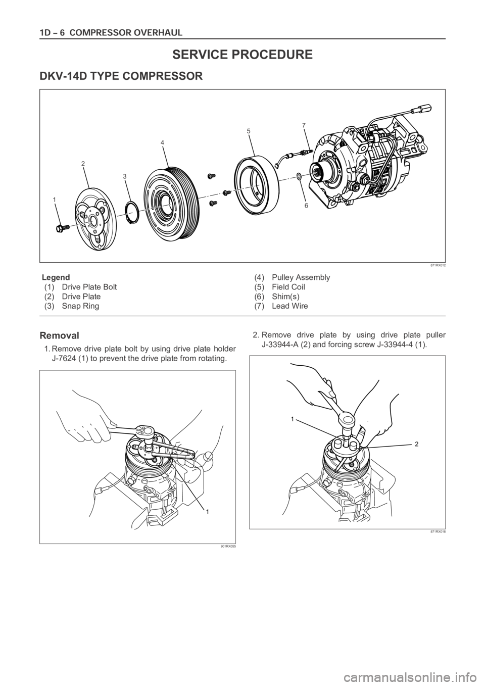
Legend
(1) Drive Plate Bolt
(2) Drive Plate
(3) Snap Ring(4) Pulley Assembly
(5) Field Coil
(6) Shim(s)
(7) Lead Wire
Removal
1. Remove drive plate bolt by using drive plate holder
J-7624 (1) to prevent the drive plate from rotating.2. Remove drive plate by using drive plate puller
J-33944-A (2) and forcing screw J-33944-4 (1).
SERVICE PROCEDURE
DKV-14D TYPE COMPRESSOR
1
2
3
4
5
67
871RX012
1
901RX055
1
2
871RX016
Page 266 of 6000
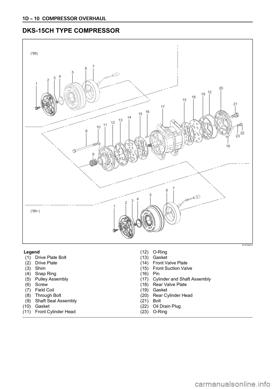
Legend
(1) Drive Plate Bolt
(2) Drive Plate
(3) Shim
(4) Snap Ring
(5) Pulley Assembly
(6) Screw
(7) Field Coil
(8) Through Bolt
(9) Shaft Seal Assembly
(10) Gasket
(11) Front Cylinder Head(12) O-Ring
(13) Gasket
(14) Front Valve Plate
(15) Front Suction Valve
(16) Pin
(17) Cylinder and Shaft Assembly
(18) Rear Valve Plate
(19) Gasket
(20) Rear Cylinder Head
(21) Bolt
(22) Oil Drain Plug
(23) O-Ring
DKS-15CH TYPE COMPRESSOR
16
23 2122 6
7
45
321 ('98)
('99~)
67
45
321
8
910111213141516
17
1518191220
871RY00015
Page 438 of 6000
4A1–1 DIFFERENTIAL (FRONT)
DRIVELINE/AXLE
CONTENTS
Differential (Front) 4A1. . . . . . . . . . . . . . . . . . . . . . .
Differential (Rear/220mm) 4A2A. . . . . . . . . . . . . . . .
Differential (Rear/244mm) 4A2B. . . . . . . . . . . . . . . .
Driveline Control System (Shift on the Fly) 4B1. . Driveline Control System (TOD) 4B2. . . . . . . . . . .
Driveshaft System 4C. . . . . . . . . . . . . . . . . . . . . . .
Transfer Case (Standard Type) 4D1. . . . . . . . . . .
Transfer Case (TOD) 4D2. . . . . . . . . . . . . . . . . . . .
DIFFERENTIAL (FRONT)
CONTENTS
Service Precaution 4A1–1. . . . . . . . . . . . . . . . . . . . . .
Front Drive Axle 4A1–2. . . . . . . . . . . . . . . . . . . . . . . . .
Diagnosis 4A1–2. . . . . . . . . . . . . . . . . . . . . . . . . . . . .
Pinion Shaft Oil Seal 4A1–3. . . . . . . . . . . . . . . . . . . . .
Pinion Shaft Oil Seal and Associated Parts 4A1–3
Removal 4A1–3. . . . . . . . . . . . . . . . . . . . . . . . . . . . .
Inspection and Repair 4A1–4. . . . . . . . . . . . . . . . . .
Installation 4A1–4. . . . . . . . . . . . . . . . . . . . . . . . . . . .
Front Drive Axle Assembly 4A1–5. . . . . . . . . . . . . . .
Front Drive Axle Assembly and
Associated Parts 4A1–5. . . . . . . . . . . . . . . . . . . . . .
Removal 4A1–5. . . . . . . . . . . . . . . . . . . . . . . . . . . . . Installation 4A1–7. . . . . . . . . . . . . . . . . . . . . . . . . . . .
Differential Assembly 4A1–9. . . . . . . . . . . . . . . . . . . .
Disassembled View 4A1–9. . . . . . . . . . . . . . . . . . . .
Disassembly 4A1–9. . . . . . . . . . . . . . . . . . . . . . . . . .
Reassembly 4A1–12. . . . . . . . . . . . . . . . . . . . . . . . . .
Differential Cage Assembly 4A1–21. . . . . . . . . . . . . . .
Disassembled View 4A1–21. . . . . . . . . . . . . . . . . . . .
Disassembly 4A1–21. . . . . . . . . . . . . . . . . . . . . . . . . .
Inspection and Repair 4A1–22. . . . . . . . . . . . . . . . . .
Reassembly 4A1–23. . . . . . . . . . . . . . . . . . . . . . . . . .
Main Data and Specifications 4A1–25. . . . . . . . . . .
Special Tools 4A1–28. . . . . . . . . . . . . . . . . . . . . . . . . .
Service Precaution
WARNING: IF SO EQUIPPED WITH A
SUPPLEMENTAL RESTRAINT SYSTEM (SRS),
REFER TO THE SRS COMPONENT AND WIRING
LOCATION VIEW IN ORDER TO DETERMINE
WHETHER YOU ARE PERFORMING SERVICE ON OR
NEAR THE SRS COMPONENTS OR THE SRS
WIRING. WHEN YOU ARE REFORMING SERVICE ON
OR NEAR THE SRS COMPONENTS OR THE SRS
WIRING, REFER TO THE SRS SERVICE
INFORMATION. FAILURE TO FOLLOW WARNINGS
COULD RESULT IN POSSIBLE AIR BAG
DEPLOYMENT, PERSONAL INJURY, OR
OTHERWISE UNNEEDED SRS SYSTEM REPAIRS.CAUTION: Always use the correct fastener in the
proper location. When you replace a fastener, use
ONLY the exact part number for that application.
ISUZU will call out those fasteners that require a
replacement after removal. ISUZU will also call out
the fasteners that require thread lockers or thread
sealant. UNLESS OTHERWISE SPECIFIED , do not
use supplemental coatings (Paints, greases, or other
corrosion inhibitors) on threaded fasteners or
fastener joint interfaces. Generally,such coatings
adversely affect the fastener torque and the joint
clamping force, and may damage the fastener. When
you install fasteners, use the correct tightening
sequence and specification. Following these
instructions can help you avoid damage to parts and
systems.
Page 462 of 6000

4A1–25 DIFFERENTIAL (FRONT)
Main Data and Specifications
General Specifications
Axle tube TypeIt consists of the duct, a cast iron housing and the axle
tube.
Gear typeHypoid
Gear ratio(to 1)4.100(6VE1)
4.300(4JX1, 6VE1)
4.555(4JG2–TC, 6VD1)
4.777(4JG2)
Differential typeTwo pinion
Oil capacityliter
(Imp qt/US qt)1.4 (1.2/1.5) (Differential)
0.12 (0.11/0.13) (Actuator Housing: Shift on the fly)
Type of lubricant75W–90 GL–5 (Multi grade type)
Refer to General Information
Axle shaft typeConstant velocity joint
(Birfield joint type and double offset joint)
Page 577 of 6000
DRIVE LINE CONTROL SYSTEM (TOD) 4B2–6
High-Low Planetary Gear Set
Establishes an auxiliary transmission mechanism. When
the transfer shift lever is set to the 2H or TOD position, the
reduction gear ratio is 1.000 and the corresponding
driving force is generated. When the transfer shift lever is
set to the 4L position, the reduction gear ratio is 2.480 and
the corresponding driving force is generated.
262RW030
4H and 4L Switches
Detects the shift position of the transfer from the
movement of the transfer lever and outputs signals to the
TOD control unit.
261RW002
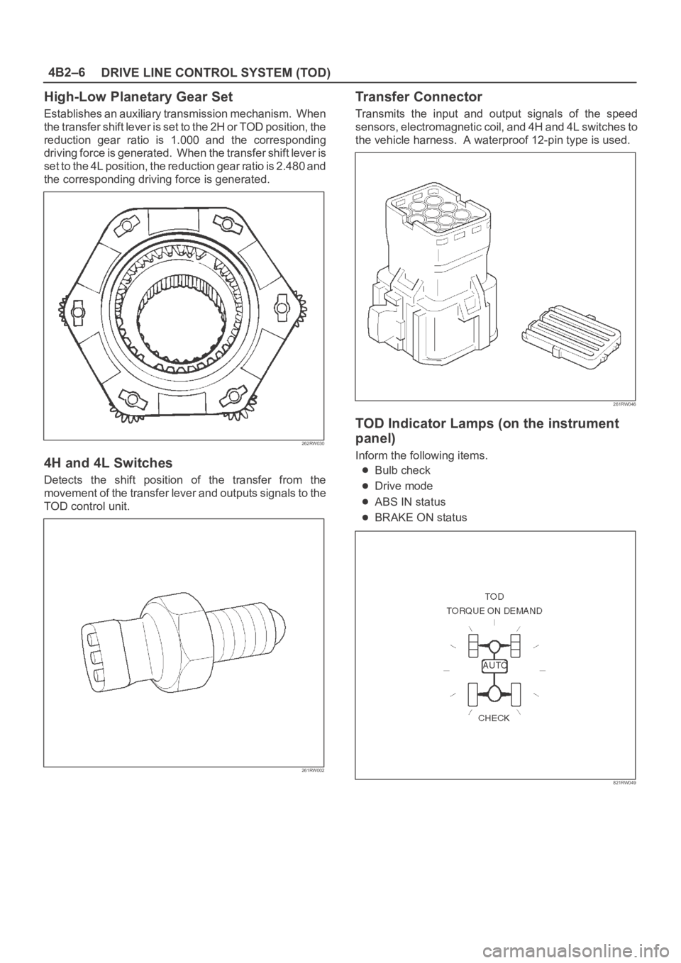
Transfer Connector
Transmits the input and output signals of the speed
sensors, electromagnetic coil, and 4H and 4L switches to
the vehicle harness. A waterproof 12-pin type is used.
261RW046
TOD Indicator Lamps (on the instrument
panel)
Inform the following items.
Bulb check
Drive mode
ABS IN status
BRAKE ON status
821RW049
Page 601 of 6000
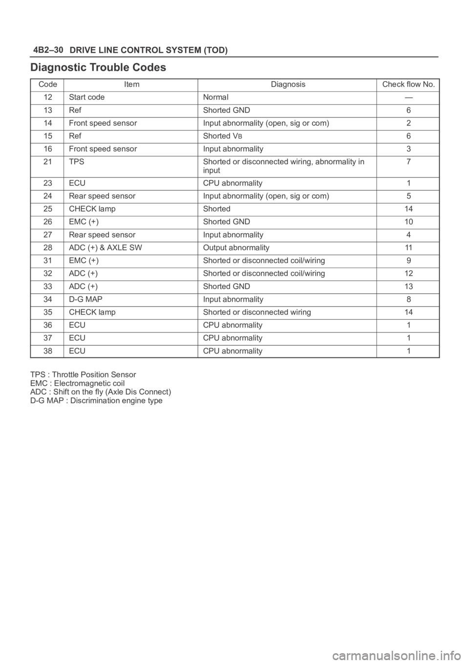
DRIVE LINE CONTROL SYSTEM (TOD) 4B2–30
Diagnostic Trouble Codes
CodeItemDiagnosisCheck flow No.
12Start codeNormal—
13RefShorted GND6
14Front speed sensorInput abnormality (open, sig or com)2
15RefShorted VB6
16Front speed sensorInput abnormality3
21TPSShorted or disconnected wiring, abnormality in
input7
23ECUCPU abnormality1
24Rear speed sensorInput abnormality (open, sig or com)5
25CHECK lampShorted14
26EMC (+)Shorted GND10
27Rear speed sensorInput abnormality4
28ADC (+) & AXLE SWOutput abnormality11
31EMC (+)Shorted or disconnected coil/wiring9
32ADC (+)Shorted or disconnected coil/wiring12
33ADC (+)Shorted GND13
34D-G MAPInput abnormality8
35CHECK lampShorted or disconnected wiring14
36ECUCPU abnormality1
37ECUCPU abnormality1
38ECUCPU abnormality1
TPS : Throttle Position Sensor
EMC : Electromagnetic coil
ADC : Shift on the fly (Axle Dis Connect)
D-G MAP : Discrimination engine type
Page 659 of 6000
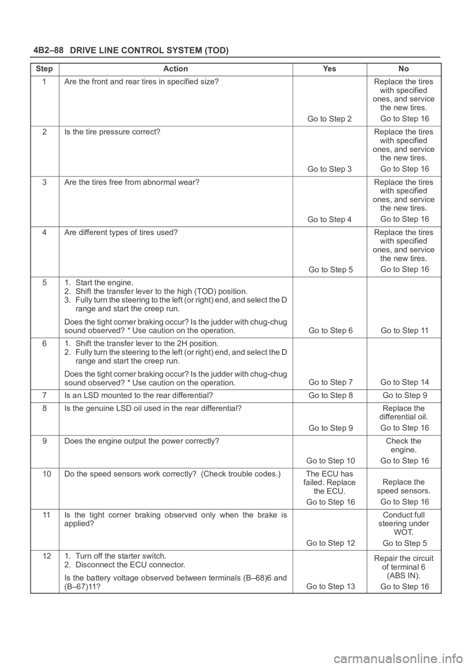
DRIVE LINE CONTROL SYSTEM (TOD) 4B2–88
StepActionYe sNo
1Are the front and rear tires in specified size?
Go to Step 2
Replace the tires
with specified
ones, and service
the new tires.
Go to Step 16
2Is the tire pressure correct?
Go to Step 3
Replace the tires
with specified
ones, and service
the new tires.
Go to Step 16
3Are the tires free from abnormal wear?
Go to Step 4
Replace the tires
with specified
ones, and service
the new tires.
Go to Step 16
4Are different types of tires used?
Go to Step 5
Replace the tires
with specified
ones, and service
the new tires.
Go to Step 16
51. Start the engine.
2. Shift the transfer lever to the high (TOD) position.
3. Fully turn the steering to the left (or right) end, and select the D
range and start the creep run.
Does the tight corner braking occur? Is the judder with chug-chug
sound observed? * Use caution on the operation.
Go to Step 6 Go to Step 11
61. Shift the transfer lever to the 2H position.
2. Fully turn the steering to the left (or right) end, and select the D
range and start the creep run.
Does the tight corner braking occur? Is the judder with chug-chug
sound observed? * Use caution on the operation.
Go to Step 7 Go to Step 14
7Is an LSD mounted to the rear differential? Go to Step 8 Go to Step 9
8Is the genuine LSD oil used in the rear differential?
Go to Step 9
Replace the
differential oil.
Go to Step 16
9Does the engine output the power correctly?
Go to Step 10
Check the
engine.
Go to Step 16
10Do the speed sensors work correctly? (Check trouble codes.)The ECU has
failed. Replace
the ECU.
Go to Step 16
Replace the
speed sensors.
Go to Step 16
11Is the tight corner braking observed only when the brake is
applied?
Go to Step 12
Conduct full
steering under
WOT.
Go to Step 5
121. Turn off the starter switch.
2. Disconnect the ECU connector.
Is the battery voltage observed between terminals (B–68)6 and
(B–67)11?
Go to Step 13
Repair the circuit
of terminal 6
(ABS IN).
Go to Step 16
Page 678 of 6000
4C–12
DRIVE SHAFT SYSTEM
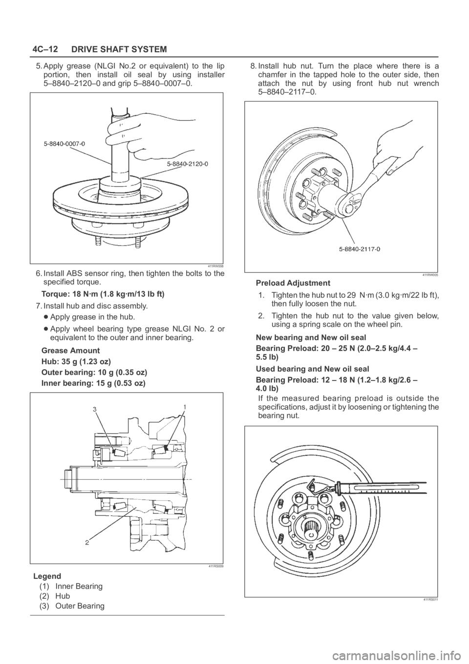
5. Apply grease (NLGI No.2 or equivalent) to the lip
portion, then install oil seal by using installer
5–8840–2120–0 and grip 5–8840–0007–0.
411RW008
6. Install ABS sensor ring, then tighten the bolts to the
specified torque.
Torque: 18 Nꞏm (1.8 kgꞏm/13 lb ft)
7. Install hub and disc assembly.
Apply grease in the hub.
Apply wheel bearing type grease NLGI No. 2 or
equivalent to the outer and inner bearing.
Grease Amount
Hub: 35 g (1.23 oz)
Outer bearing: 10 g (0.35 oz)
Inner bearing: 15 g (0.53 oz)
411RS009
Legend
(1) Inner Bearing
(2) Hub
(3) Outer Bearing
8. Install hub nut. Turn the place where there is a
chamfer in the tapped hole to the outer side, then
attach the nut by using front hub nut wrench
5–8840–2117–0.
411RW005
Preload Adjustment
1. Tighten the hub nut to 29 Nꞏm (3.0 kgꞏm/22 lb ft),
then fully loosen the nut.
2. Tighten the hub nut to the value given below,
using a spring scale on the wheel pin.
New bearing and New oil seal
Bearing Preload: 20 – 25 N (2.0–2.5 kg/4.4 –
5.5 lb)
Used bearing and New oil seal
Bearing Preload: 12 – 18 N (1.2–1.8 kg/2.6 –
4.0 lb)
If the measured bearing preload is outside the
specifications, adjust it by loosening or tightening the
bearing nut.
411RS011
Page 684 of 6000

4C–18
DRIVE SHAFT SYSTEM
17. Install oil seal by using installer 5–8840–2120–0 and
grip 5–8840–0007–0.
Apply grease (NLGI No.2 or equivalent) to the lip
portion.
411RW008
18. Install ABS sensor ring (if so equipped).
Tighten the bolts to the specified torque.
Torque:18Nꞏm (1.8kgꞏm/13lbft)
19. Install hub and disc assembly.
1. Apply grease in the hub.
2. Apply wheel bearing type grease NLGI No.2 or
equivalent to the outer and inner bearing.
Grease Amount
Hub: 35 g (1.23 oz)
Outer bearing: 10 g (0.35 oz)
Inner bearing: 15 g (0.53 oz)
20. Install hub nut.
1. Turn the place where there is a chamfer in the
tapped hole to the outer side, and attach the nut
by using wrench 5–8840–2117–0.
411RW005
Preload Adjustment
Tighten the hub nut to 29 Nꞏm (3.0 kgꞏm/22 lbꞏft),
then fully loosen the nut.
Tighten the hub nut to the value given below, using
a spring scale on the wheel pin.
Bearing Preload
New bearing and New oil seal:
20-25N (2-2.5 kg/4.4-5.5 lb)
Used bearing and New oil seal:
12-18N (1.2-1.8 kg/2.6-4.0 lb)
If the measured bearing preload is outside the
specifications, adjust it by loosening or tightening
the bearing nut.
411RS011
Page 701 of 6000

4C–35 DRIVE SHAFT SYSTEM
Main Data and Specifications
General Specifications
Front drive axle oil capacity1.4 liter (1.23 Imp qt/1.48 US qt)(Differential)
0.12 liter (0.10 Imp qt/0.13 US qt)(Actuator Housing:Shift on the fly)
Type of lubricantGL–5 (Multi grade type) Refer to chart in General Information
Axle shaft typeConstant velocity joint(Birfield joint type and double offset joint)
Torque Specifications
E04RW020