reset OPEL FRONTERA 1998 Owner's Manual
[x] Cancel search | Manufacturer: OPEL, Model Year: 1998, Model line: FRONTERA, Model: OPEL FRONTERA 1998Pages: 6000, PDF Size: 97 MB
Page 1993 of 6000

6E–100
4JX1–TC ENGINE DRIVEABILITY AND EMISSIONS
DTC P0201 – Injector # 1 Circuit Fault
StepActionVa l u e ( s )Ye sNo
1Was the “On-Board Diagnostic (OBD) System Check”
performed?
—Go to Step 2
Go to OBD
System
Check
2Will the engine start?
—Go to Step 3
Go to Engine
Cranks But
Will Not Run
chart
31. Install the Tech 2. Clear the DTC.
2. Idle the engine for one minute.
Does DTC P0201 reset?
—Go to Step 5Go to Step 4
41. Review the Freeze Frame data with the ignition
“ON” and the engine “OFF” and note the
parameters.
2. Operate the vehicle within the Freeze Frame
conditions as noted.
Does P0201 reset?
—Go to Step 5—
5Check the Injector test.
Does the working noise confirm?
—Go to Step 6Go to Step 7
61. Install the Tech 2. Clear the DTC.
2. Idle the engine for one minute.
Dose DTC P0201 reset?
—Verify repairGo to Step 7
7Check for an open circuit between the injector
connector and the ECM.
Was there an open circuit?
—Go to Step 8Go to Step 9
8Repair the open circuit.
Is the action complete?
—Verify repair—
9Replace the ECM (Refer to the Data Programming in
Case of ECM change).
Is the action complete?
—Verify repairGo to Step 10
10Replace the Injector (Refer to the Injector Group Sign
Programming).
Is the action complete?
—Verify repair—
Page 1995 of 6000

6E–102
4JX1–TC ENGINE DRIVEABILITY AND EMISSIONS
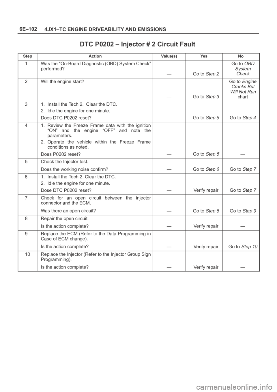
DTC P0202 – Injector # 2 Circuit Fault
StepActionVa l u e ( s )Ye sNo
1Was the “On-Board Diagnostic (OBD) System Check”
performed?
—Go to Step 2
Go to OBD
System
Check
2Will the engine start?
—Go to Step 3
Go to Engine
Cranks But
Will Not Run
chart
31. Install the Tech 2. Clear the DTC.
2. Idle the engine for one minute.
Does DTC P0202 reset?
—Go to Step 5Go to Step 4
41. Review the Freeze Frame data with the ignition
“ON” and the engine “OFF” and note the
parameters.
2. Operate the vehicle within the Freeze Frame
conditions as noted.
Does P0202 reset?
—Go to Step 5—
5Check the Injector test.
Does the working noise confirm?
—Go to Step 6Go to Step 7
61. Install the Tech 2. Clear the DTC.
2. Idle the engine for one minute.
Dose DTC P0202 reset?
—Verify repairGo to Step 7
7Check for an open circuit between the injector
connector and the ECM.
Was there an open circuit?
—Go to Step 8Go to Step 9
8Repair the open circuit.
Is the action complete?
—Verify repair—
9Replace the ECM (Refer to the Data Programming in
Case of ECM change).
Is the action complete?
—Verify repairGo to Step 10
10Replace the Injector (Refer to the Injector Group Sign
Programming).
Is the action complete?
—Verify repair—
Page 1997 of 6000

6E–104
4JX1–TC ENGINE DRIVEABILITY AND EMISSIONS
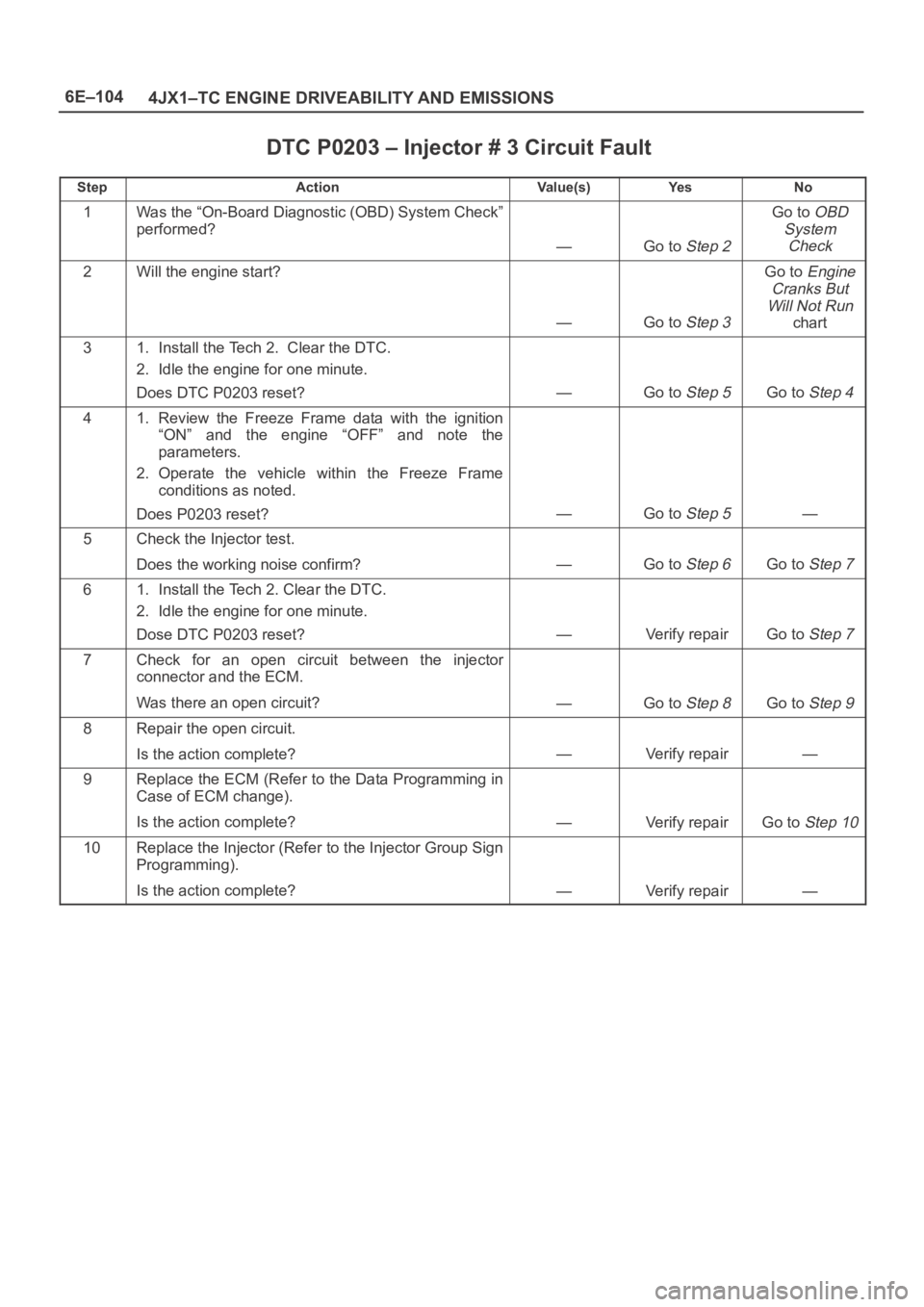
DTC P0203 – Injector # 3 Circuit Fault
StepActionVa l u e ( s )Ye sNo
1Was the “On-Board Diagnostic (OBD) System Check”
performed?
—Go to Step 2
Go to OBD
System
Check
2Will the engine start?
—Go to Step 3
Go to Engine
Cranks But
Will Not Run
chart
31. Install the Tech 2. Clear the DTC.
2. Idle the engine for one minute.
Does DTC P0203 reset?
—Go to Step 5Go to Step 4
41. Review the Freeze Frame data with the ignition
“ON” and the engine “OFF” and note the
parameters.
2. Operate the vehicle within the Freeze Frame
conditions as noted.
Does P0203 reset?
—Go to Step 5—
5Check the Injector test.
Does the working noise confirm?
—Go to Step 6Go to Step 7
61. Install the Tech 2. Clear the DTC.
2. Idle the engine for one minute.
Dose DTC P0203 reset?
—Verify repairGo to Step 7
7Check for an open circuit between the injector
connector and the ECM.
Was there an open circuit?
—Go to Step 8Go to Step 9
8Repair the open circuit.
Is the action complete?
—Verify repair—
9Replace the ECM (Refer to the Data Programming in
Case of ECM change).
Is the action complete?
—Verify repairGo to Step 10
10Replace the Injector (Refer to the Injector Group Sign
Programming).
Is the action complete?
—Verify repair—
Page 1999 of 6000

6E–106
4JX1–TC ENGINE DRIVEABILITY AND EMISSIONS
DTC P0204 – Injector #4 Circuit Fault
StepActionVa l u e ( s )Ye sNo
1Was the “On-Board Diagnostic (OBD) System Check”
performed?
—Go to Step 2
Go to OBD
System
Check
2Will the engine start?
—Go to Step 3
Go to Engine
Cranks But
Will Not Run
chart
31. Install the Tech 2. Clear the DTC.
2. Idle the engine for one minute.
Does DTC P0204 reset?
—Go to Step 5Go to Step 4
41. Review the Freeze Frame data with the ignition
“ON” and the engine “OFF” and note the
parameters.
2. Operate the vehicle within the Freeze Frame
conditions as noted.
Does P0204 reset?
—Go to Step 5—
5Check the Injector test.
Does the working noise confirm?
—Go to Step 6Go to Step 7
61. Install the Tech 2. Clear the DTC.
2. Idle the engine for one minute.
Dose DTC P0204 reset?
—Verify repairGo to Step 7
7Check for an open circuit between the injector
connector and the ECM.
Was there an open circuit?
—Go to Step 8Go to Step 9
8Repair the open circuit.
Is the action complete?
—Verify repair—
9Is the action complete?—Verify repairGo to Step 10
10Replace the Injector (Refer to the Injector Group Sign
Programming).
Is the action complete?
—Verify repair—
Page 2609 of 6000

Circuit Breaker
The circuit breaker is a protective device designed to
open the circuit when a current load is in excess of rated
breaker capacity. If there is a short or other type of
overload condition in the circuit, the excessive current will
open the circuit between the circuit breaker terminals.
The reset knob (1) pops out when the circuit is open. Push
the reset knob in place to restore the circuit after repairing
it.
Relay
Battery and load location may require that a switch be
placed some distance from either component. This
means a longer wire and a higher voltage drop (1).
The installation of a relay between the battery and the
load reduces the voltage drop (2).
Because the switch controls the relay, amperage through
the switch can be reduced.
LOAD
12LOAD
RELAY
D08RW404
1
Page 3004 of 6000

D08RW722
3C-3910
H-42
0.5
B/R0.5
B/R 0.5
B/R
B
D
C
A
FENDER-RH
H-104
M-10
2
A
I 0.5
L/Y0.5
L/Y0.5
L/Y
1M-109
H-103
H-9
0.5
LG/W0.5
LG/W
0.5
LG/W0.5
LG/W 0.5
LG/W0.5
R/W
SPEEDO-
METER
RESET
SWTACHOMETERENGINE
COOLANT
TEMPERATURE
GAUGEFUEL
GAUGEOIL
PRESSURE
GAUGE FUSE C-15
3M-10125
H-9
11
H-10
VEHICLE
SPEED SENSOR
I-10
0.5
Y/B0.5
Y/B0.5
Y/B
1
E-191 4
H-24
11
H-6
I-10
2H-8
PCM
(D7)CRUISE CONTROL
UNIT(9)0.5
B/R
15H-9
PCM
(C10)9
I-9
0.5
Y/R
14
H-2520
I-10
ENGINE
COOLANT
TEMPERATURE
UNIT
0.5
Y/G0.5
Y/V0.5
Y/B
1
E-217 19
H-9
10
H-6
I-10
OIL
PRESSURE
UNIT
8I-10METER
ODO/TRIP
METER
Page 3010 of 6000

D08RW731
3C-3910
H-42
0.5
B/R0.5
B/R 0.5
B/R
B
D
C
A
FENDER-RH
H-104
M-10
2
A
I 0.5
L/Y0.5
L/Y0.5
L/Y
1M-109
H-103
H-9
0.5
LG/W0.5
LG/W
0.5
LG/W0.5
LG/W 0.5
LG/W0.5
R/W
SPEEDO-
METER
RESET
SWTACHOMETERENGINE
COOLANT
TEMPERATURE
GAUGEFUEL
GAUGE FUSE C-15
3M-10125
H-9
11
H-10
VEHICLE
SPEED SENSOR
I-10
0.5
Y/B0.5
Y/B0.5
Y/B
1
E-191 9
H-24
11
H-6
I-10
2H-8
PCM
(D7)CRUISE CONTROL
UNIT(9)0.5
B/R
15H-9
PCM
(C10)9
I-9
0.5
Y/R
14
H-2520
I-10
ENGINE
COOLANT
TEMPERATURE
UNIT
8I-10METER
ODO/TRIP
METER
��
Page 3016 of 6000

D08RW738
6C-3910
H-41
0.5
B/R0.5
B 0.5
B/R
FENDER-RH
H-514
E-20
2
0.5
Y 0.5
L/Y0.5
L/Y
1E-2016
H-5
H-93
0.5
LG/W0.5
LG/W
0.3
LG/W0.3
LG/W 0.5
LG/W0.5
R/W
SPEEDO-
METER
RESET
SWTACHOMETERENGINE
COOLANT
TEMPERATURE
GAUGEFUEL
GAUGEOIL
PRESSURE
GAUGE FUSE C-15
3E-20125
H-9
15
H-5
VEHICLE
SPEED SENSOR
I-10
0.5
Y/B0.5
Y/B0.5
Y/B
1
E-191 4
H-24
4
H-5
I-10
QOS-III
CONTROL
UNIT
(9)QOS/EGR
CONTROL
UNIT
(16)0.5
BR
0.5
BR
0.5
BR
0.5
BP15
H-9
6
H-49
I-9
1
E-36
0.5
Y/R
14
H-2520
I-10
ENGINE
COOLANT
TEMPERATURE
UNIT TACHO
SENSOR
0.5
Y/V0.5
LB 0.5
Y/V0.5
Y/B
1
E-217 19
H-9
2
H-5
2E-23
H-5
0.5
BP 0.5
BP6C-39
FENDER-RH4
H-42
I-10
OIL
PRESSURE
UNIT
8I-10METER
ODO/TRIP
METER
E-36
2
10
H-4
Page 3024 of 6000

D08RW924
8C-3910
H-42
0.5
B/R0.5
B/R 0.5
B/R
B
D
C
A
FENDER-RH
H-104
M-10
2
A
I 0.5
L/Y0.5
L/Y0.5
L/Y
1M-109
H-105
H-24
0.5
LG/W0.5
LG/W
0.5
LG/W0.5
LG/W 0.5
LG/W0.5
R/W
SPEEDO-
METER
RESET
SWTACHOMETERENGINE
COOLANT
TEMPERATURE
GAUGEFUEL
GAUGEOIL
PRESSURE
GAUGE FUSE C-15
3M-10145
H-9
11
H-10
VEHICLE
SPEED SENSOR
I-10
0.5
Y/B0.5
Y/B0.5
Y/B
1
E-191 4
H-9
11
H-6
I-10
8H-8
PCM
(D7)CRUISE CONTROL
UNIT(9)0.5
B/R
18H-9
PCM
(C10)9
I-9
0.5
Y/R
13
H-2620
I-10
ENGINE
COOLANT
TEMPERATURE
UNIT
0.5
Y/G0.5
Y/B0.5
Y/B
1
E-212 19
H-9
10
H-6
I-10
OIL
PRESSURE
UNIT
8I-10METER
ODO/TRIP
METER
Page 3030 of 6000

D08RW915
8C-3910
H-41
0.5
B/R0.5
B 0.5
B/R
FENDER-RH
H-514
E-20
2
0.5
Y 0.5
L/Y0.5
L/Y
1E-2016
H-5
H-245
0.5
LG/W0.5
LG/W
0.3
LG/W0.3
LG/W 0.5
LG/W0.5
R/W
SPEEDO-
METER
RESET
SWTACHOMETERENGINE
COOLANT
TEMPERATURE
GAUGEFUEL
GAUGEOIL
PRESSURE
GAUGE FUSE C-15
3E-20145
H-9
15
H-5
VEHICLE
SPEED SENSOR
I-10
0.5
Y/B0.5
Y/B0.5
Y/B
1
E-191 4
H-9
4
H-5
I-10
QOS-III
CONTROL
UNIT
(9)QOS/EGR
CONTROL
UNIT
(16)0.5
BR
0.5
BR
0.5
BR
0.5
BP18
H-9
6
H-49
I-9
1
E-36
0.5
Y/R
13
H-2620
I-10
ENGINE
COOLANT
TEMPERATURE
UNIT TACHO
SENSOR
0.5
Y/V0.5
LB 0.5
Y/V0.5
Y/B
1
E-212 19
H-9
2
H-5
2E-23
H-5
0.5
BP 0.5
BP7C-39
FENDER-RH4
H-42
I-10
OIL
PRESSURE
UNIT
8I-10METER
ODO/TRIP
METER
E-36
2
10
H-4