engine oil OPEL FRONTERA 1998 Workshop Manual
[x] Cancel search | Manufacturer: OPEL, Model Year: 1998, Model line: FRONTERA, Model: OPEL FRONTERA 1998Pages: 6000, PDF Size: 97 MB
Page 3016 of 6000

D08RW738
6C-3910
H-41
0.5
B/R0.5
B 0.5
B/R
FENDER-RH
H-514
E-20
2
0.5
Y 0.5
L/Y0.5
L/Y
1E-2016
H-5
H-93
0.5
LG/W0.5
LG/W
0.3
LG/W0.3
LG/W 0.5
LG/W0.5
R/W
SPEEDO-
METER
RESET
SWTACHOMETERENGINE
COOLANT
TEMPERATURE
GAUGEFUEL
GAUGEOIL
PRESSURE
GAUGE FUSE C-15
3E-20125
H-9
15
H-5
VEHICLE
SPEED SENSOR
I-10
0.5
Y/B0.5
Y/B0.5
Y/B
1
E-191 4
H-24
4
H-5
I-10
QOS-III
CONTROL
UNIT
(9)QOS/EGR
CONTROL
UNIT
(16)0.5
BR
0.5
BR
0.5
BR
0.5
BP15
H-9
6
H-49
I-9
1
E-36
0.5
Y/R
14
H-2520
I-10
ENGINE
COOLANT
TEMPERATURE
UNIT TACHO
SENSOR
0.5
Y/V0.5
LB 0.5
Y/V0.5
Y/B
1
E-217 19
H-9
2
H-5
2E-23
H-5
0.5
BP 0.5
BP6C-39
FENDER-RH4
H-42
I-10
OIL
PRESSURE
UNIT
8I-10METER
ODO/TRIP
METER
E-36
2
10
H-4
Page 3024 of 6000

D08RW924
8C-3910
H-42
0.5
B/R0.5
B/R 0.5
B/R
B
D
C
A
FENDER-RH
H-104
M-10
2
A
I 0.5
L/Y0.5
L/Y0.5
L/Y
1M-109
H-105
H-24
0.5
LG/W0.5
LG/W
0.5
LG/W0.5
LG/W 0.5
LG/W0.5
R/W
SPEEDO-
METER
RESET
SWTACHOMETERENGINE
COOLANT
TEMPERATURE
GAUGEFUEL
GAUGEOIL
PRESSURE
GAUGE FUSE C-15
3M-10145
H-9
11
H-10
VEHICLE
SPEED SENSOR
I-10
0.5
Y/B0.5
Y/B0.5
Y/B
1
E-191 4
H-9
11
H-6
I-10
8H-8
PCM
(D7)CRUISE CONTROL
UNIT(9)0.5
B/R
18H-9
PCM
(C10)9
I-9
0.5
Y/R
13
H-2620
I-10
ENGINE
COOLANT
TEMPERATURE
UNIT
0.5
Y/G0.5
Y/B0.5
Y/B
1
E-212 19
H-9
10
H-6
I-10
OIL
PRESSURE
UNIT
8I-10METER
ODO/TRIP
METER
Page 3030 of 6000

D08RW915
8C-3910
H-41
0.5
B/R0.5
B 0.5
B/R
FENDER-RH
H-514
E-20
2
0.5
Y 0.5
L/Y0.5
L/Y
1E-2016
H-5
H-245
0.5
LG/W0.5
LG/W
0.3
LG/W0.3
LG/W 0.5
LG/W0.5
R/W
SPEEDO-
METER
RESET
SWTACHOMETERENGINE
COOLANT
TEMPERATURE
GAUGEFUEL
GAUGEOIL
PRESSURE
GAUGE FUSE C-15
3E-20145
H-9
15
H-5
VEHICLE
SPEED SENSOR
I-10
0.5
Y/B0.5
Y/B0.5
Y/B
1
E-191 4
H-9
4
H-5
I-10
QOS-III
CONTROL
UNIT
(9)QOS/EGR
CONTROL
UNIT
(16)0.5
BR
0.5
BR
0.5
BR
0.5
BP18
H-9
6
H-49
I-9
1
E-36
0.5
Y/R
13
H-2620
I-10
ENGINE
COOLANT
TEMPERATURE
UNIT TACHO
SENSOR
0.5
Y/V0.5
LB 0.5
Y/V0.5
Y/B
1
E-212 19
H-9
2
H-5
2E-23
H-5
0.5
BP 0.5
BP7C-39
FENDER-RH4
H-42
I-10
OIL
PRESSURE
UNIT
8I-10METER
ODO/TRIP
METER
E-36
2
10
H-4
Page 3179 of 6000

8E–2METER AND GAUGE
Meter Assembly
General Description
The meter assembly has the speedometer, tachometer,
engine coolant temperature gauge, fuel gauge and
warning/indicator lights. In addition, the meter assembly
containing TOD (Torque on Demand) has the TOD
indicator light, or the meter assembly not containing TOD
has the voltmeter and oil pressure gauge instead of the
TOD indicator.
Layout for Meters/Gauges, Warning Lights, Indicator Lights and Illumination
Lights
Meter Assembly–Gasoline W/O TOD (Front View)
825RW207
Legend
(1) Voltmeter & Engine Coolant Temperature
Gauge
(2) Tachometer
(3) Warning Light Lens
(4) Speedometer(5) Oil Pressure Gauge & Fuel Gauge
(6) Warning Light Lens
(7) Reset Knob
(8) A/T Shift Indicator
(9) Warning Light Lens
Page 3186 of 6000

METER AND GAUGE8E–9
Meter Assembly–Gasoline W/O TOD–2
Connector No. I–9
Te r m i n a lFunction
1A/T oil temp warning light
2Seat belt warning light
3Check trans warning light
4Brake warning light
5Check engine warning light
6Charge warning light
7Cigarette lighter illumination light
8Illumination controller
9Tachometer
10D position (A/T)
11—
12A/T shift indicator control unit
13—
142 position (A/T)
15Starter switch
16Cruise set indicator light
17Cruise main indicator light
184WD indicator light
19Ground (Gauge)
20—
21Winter drive indicator light
22Oil pressure warning light
23—
24Air bag warning light
25Power drive indicator light
26—
27—
28Turn signal indicator light (Left)
29—
30Ground
Connector No. I–10
Te r m i n a lFunction
1Turn signal indicator light (Right)
2L position (A/T)
3R position (A/T)
4Engine coolant temperature gauge
5Speedometer
6—
7—
8Battery (+)
9—
10Rear fog light
11P position (A/T)
12N position (A/T)
133 position (A/T)
14High-beam indicator light (–)
15High-beam indicator light (+)
16ABS indicator light
17—
18Fuel warning light
19Oil pressure gauge
20Fuel gauge
21—
22—
Page 3188 of 6000

METER AND GAUGE8E–11
Meter Assembly–Gasoline W/TOD–2
Connector No. I–9
Te r m i n a lFunction
1—
2Air bag warning light
3A/T oil temp warning light
4Charge warning light
5Check engine warning light
6Check trans warning light
7Brake warning light
8—
9Tachometer
10—
11Turn signal indicator light (Left)
12A/T shift indicator control unit
132 position (A/T)
14D position (A/T)
15Rear (TOD)
16Auto (TOD)
17Check (TOD)
18Cruise set indicator light
19Cruise main indicator light
20Oil pressure warning light
21Front “1” (TOD)
22Front “2” (TOD)
23Front “3” (TOD)
24Cigarette lighter illumination light
25Illumination controller
26Starter switch
27—
28Winter drive indicator light
29Power drive indicator light
30—
Connector No. I–10
Te r m i n a lFunction
1Turn signal indicator light (Right)
2L position (A/T)
3R position (A/T)
4Check engine warning light
5Speedometer
6—
7—
8Battery (+)
9Engine coolant temperature gauge
10Ground
11P position (A/T)
12N position (A/T)
133 position (A/T)
14High beam indicator light (–)
15High beam indicator light (+)
16ABS indicator light
17—
18Fuel warning light
19—
20Fuel gauge
21Ground (Gauge)
22—
Page 3190 of 6000

METER AND GAUGE8E–13
Meter Assembly–Diesel–2
Connector No. I–9
Te r m i n a lFunction
1—
2Seat belt warning light
3—
4Brake warning light
5—
6Charge warning light
7Cigarette lighter illumination light
8Illumination controller
9Tachometer
10—
11—
12—
13—
14—
15Starter switch
16—
17—
184WD indicator light
19Ground (Gauge)
20—
21—
22Oil pressure warning light
23Water sedimenter
24Air bag warning light
25—
26Glow indicator light
27—
28Turn signal indicator light (Left)
29—
30Ground
Connector No. I–10
Te r m i n a lFunction
1Turn signal indicator light (Right)
2—
3—
4Engine coolant temperature gauge
5Speedometer
6—
7—
8Battery (+)
9—
10—
11—
12—
13—
14High-beam indicator light (–)
15High-beam indicator light (+)
16ABS indicator light
17—
18Fuel warning light
19Oil pressure gauge
20Fuel gauge
21—
22—
Page 3441 of 6000

SUPPLEMENTAL RESTRAINT SYSTEM 9J–4
SRS Component And Wiring Location View
810RW298
Legend
(1) Battery
(2) Relay & Fuse Box
(3) Passenger Air Bag Assembly
(4) SDM
(5) Meter Assembly
(6) SRS Coil Assembly
(7) Driver Air Bag Assembly(8) Starter Switch
(9) Fuse Box, C–21
(10) SRS Body Earth
(11) Body Harness Connector
(12) Instrument Harness Connector
(13) Engine Haness Connector
(14) Pretensioner, LH (If so equipped)
(15) Pretensioner, RH (If so equipped)
Component Description
SDM (Sensing and Diagnostic Module)
WARNING: DURING SERVICE PROCEDURES, BE
VERY CAREFUL WHEN HANDLING A SENSING AND
DIAGNOSTIC MODULE (SDM). NEVER STRIKE OR
JAR THE SDM. NEVER POWER UP THE SRS WHEN
THE SDM IS NOT RIGIDLY ATTACHED TO THE
VEHICLE. ALL SDM AND MOUNTING BRACKETFASTENERS MUST BE CAREFULLY TORQUED AND
THE ARROW MUST BE POINTED TOWARD THE
FRONT OF THE VEHICLE TO ENSURE PROPER
OPERATION OF THE SRS. THE SDM COULD BE
ACTIVATED WHEN POWERED WHILE NOT RIGIDLY
ATTACHED TO THE VEHICLE WHICH COULD CAUSE
DEPLOYMENT AND RESULT IN PERSONAL INJURY.
The Sensing and Diagnostic Module (SDM) is designed
to perform the following functions in the SRS:
Page 3477 of 6000

SUPPLEMENTAL RESTRAINT SYSTEM 9J–40
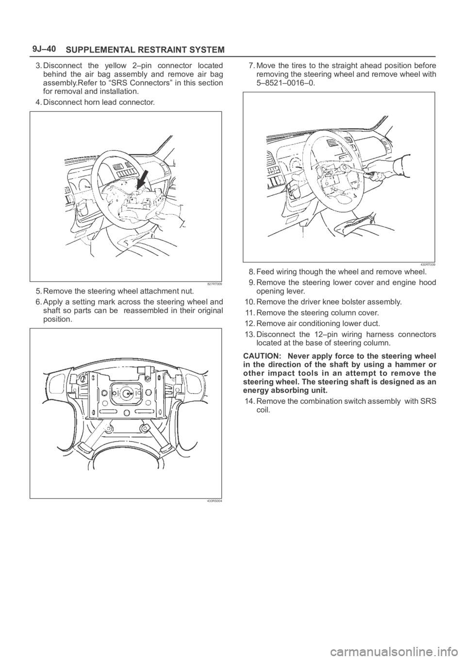
3. Disconnect the yellow 2–pin connector located
behind the air bag assembly and remove air bag
assembly.Refer to “SRS Connectors” in this section
for removal and installation.
4. Disconnect horn lead connector.
827RT009
5. Remove the steering wheel attachment nut.
6. Apply a setting mark across the steering wheel and
shaft so parts can be reassembled in their original
position.
430RS004
7. Move the tires to the straight ahead position before
removing the steering wheel and remove wheel with
5–8521–0016–0.
430RT009
8. Feed wiring though the wheel and remove wheel.
9. Remove the steering lower cover and engine hood
opening lever.
10. Remove the driver knee bolster assembly.
11. Remove the steering column cover.
12. Remove air conditioning lower duct.
13. Disconnect the 12–pin wiring harness connectors
located at the base of steering column.
CAUTION: Never apply force to the steering wheel
in the direction of the shaft by using a hammer or
other impact tools in an attempt to remove the
steering wheel. The steering shaft is designed as an
energy absorbing unit.
14. Remove the combination switch assembly with SRS
coil.
Page 3478 of 6000

SUPPLEMENTAL RESTRAINT SYSTEM9J–41
Installation
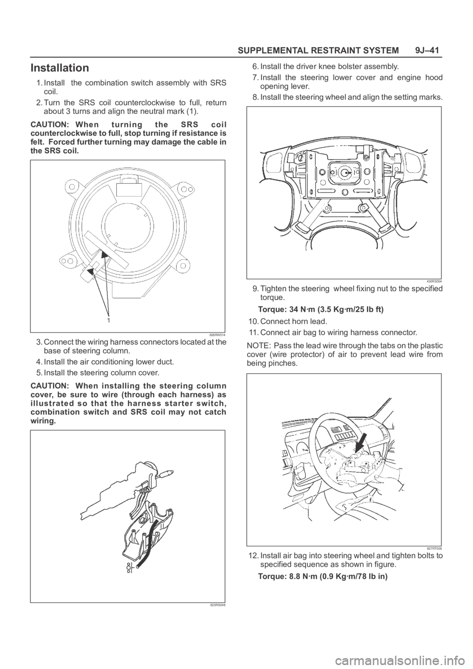
1. Install the combination switch assembly with SRS
coil.
2. Turn the SRS coil counterclockwise to full, return
about 3 turns and align the neutral mark (1).
CAUTION: W h e n t u r n i n g t h e S R S c o i l
counterclockwise to full, stop turning if resistance is
felt. Forced further turning may damage the cable in
the SRS coil.
826RW014
3. Connect the wiring harness connectors located at the
base of steering column.
4. Install the air conditioning lower duct.
5. Install the steering column cover.
CAUTION: When installing the steering column
cover, be sure to wire (through each harness) as
illustrated so that the harness starter switch,
combination switch and SRS coil may not catch
wiring.
825RS048
6. Install the driver knee bolster assembly.
7. Install the steering lower cover and engine hood
opening lever.
8. Install the steering wheel and align the setting marks.
430RS004
9. Tighten the steering wheel fixing nut to the specified
torque.
Torque: 34 Nꞏm (3.5 Kgꞏm/25 Ib ft)
10. Connect horn lead.
11. Connect air bag to wiring harness connector.
NOTE: Pass the lead wire through the tabs on the plastic
cover (wire protector) of air to prevent lead wire from
being pinches.
827RT009
12. Install air bag into steering wheel and tighten bolts to
specified sequence as shown in figure.
Torque: 8.8 Nꞏm (0.9 Kgꞏm/78 Ib in)