horn OPEL FRONTERA 1998 Owner's Guide
[x] Cancel search | Manufacturer: OPEL, Model Year: 1998, Model line: FRONTERA, Model: OPEL FRONTERA 1998Pages: 6000, PDF Size: 97 MB
Page 3481 of 6000
SUPPLEMENTAL RESTRAINT SYSTEM 9J–44
Installation
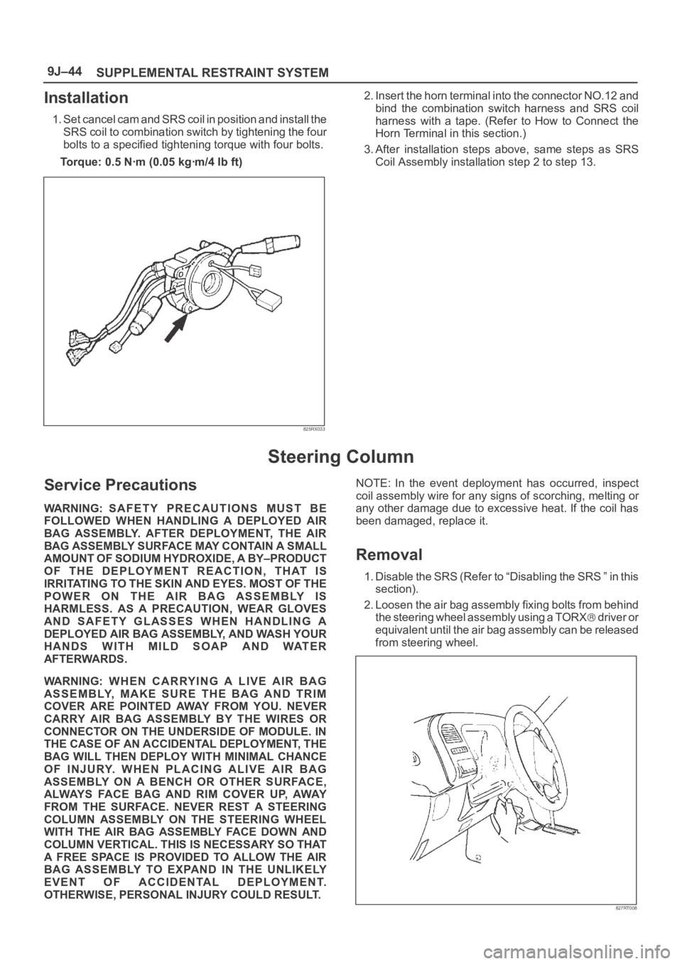
1. Set cancel cam and SRS coil in position and install the
SRS coil to combination switch by tightening the four
bolts to a specified tightening torque with four bolts.
Torque: 0.5 Nꞏm (0.05 kgꞏm/4 Ib ft)
825RX033
2. Insert the horn terminal into the connector NO.12 and
bind the combination switch harness and SRS coil
harness with a tape. (Refer to How to Connect the
Horn Terminal in this section.)
3. After installation steps above, same steps as SRS
Coil Assembly installation step 2 to step 13.
Steering Column
Service Precautions
WARNING: SAFETY PRECAUTIONS MUST BE
FOLLOWED WHEN HANDLING A DEPLOYED AIR
BAG ASSEMBLY. AFTER DEPLOYMENT, THE AIR
BAG ASSEMBLY SURFACE MAY CONTAIN A SMALL
AMOUNT OF SODIUM HYDROXIDE, A BY–PRODUCT
OF THE DEPLOYMENT REACTION, THAT IS
IRRITATING TO THE SKIN AND EYES. MOST OF THE
POWER ON THE AIR BAG ASSEMBLY IS
HARMLESS. AS A PRECAUTION, WEAR GLOVES
AND SAFETY GLASSES WHEN HANDLING A
DEPLOYED AIR BAG ASSEMBLY, AND WASH YOUR
HANDS WITH MILD SOAP AND WATER
AFTERWARDS.
WARNING: WHEN CARRYING A LIVE AIR BAG
ASSEMBLY, MAKE SURE THE BAG AND TRIM
COVER ARE POINTED AWAY FROM YOU. NEVER
CARRY AIR BAG ASSEMBLY BY THE WIRES OR
CONNECTOR ON THE UNDERSIDE OF MODULE. IN
THE CASE OF AN ACCIDENTAL DEPLOYMENT, THE
BAG WILL THEN DEPLOY WITH MINIMAL CHANCE
OF INJURY. WHEN PLACING ALIVE AIR BAG
ASSEMBLY ON A BENCH OR OTHER SURFACE,
ALWAYS FACE BAG AND RIM COVER UP, AWAY
FROM THE SURFACE. NEVER REST A STEERING
COLUMN ASSEMBLY ON THE STEERING WHEEL
WITH THE AIR BAG ASSEMBLY FACE DOWN AND
COLUMN VERTICAL. THIS IS NECESSARY SO THAT
A FREE SPACE IS PROVIDED TO ALLOW THE AIR
BAG ASSEMBLY TO EXPAND IN THE UNLIKELY
EVENT OF ACCIDENTAL DEPLOYMENT.
OTHERWISE, PERSONAL INJURY COULD RESULT.NOTE: In the event deployment has occurred, inspect
coil assembly wire for any signs of scorching, melting or
any other damage due to excessive heat. If the coil has
been damaged, replace it.
Removal
1. Disable the SRS (Refer to “Disabling the SRS ” in this
section).
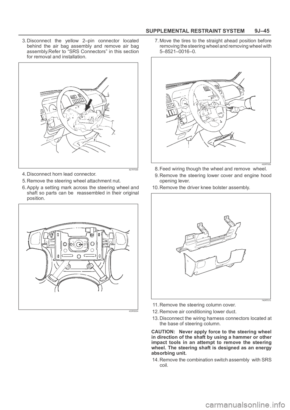
2. Loosen the air bag assembly fixing bolts from behind
the steering wheel assembly using a TORX
d r i v e r o r
equivalent until the air bag assembly can be released
from steering wheel.
827RT008
Page 3482 of 6000
SUPPLEMENTAL RESTRAINT SYSTEM9J–45
3. Disconnect the yellow 2–pin connector located
behind the air bag assembly and remove air bag
assembly.Refer to “SRS Connectors” in this section
for removal and installation.
827RT009
4. Disconnect horn lead connector.
5. Remove the steering wheel attachment nut.
6. Apply a setting mark across the steering wheel and
shaft so parts can be reassembled in their original
position.
430RS004
7. Move the tires to the straight ahead position before
removing the steering wheel and removing wheel with
5–8521–0016–0.
430RT009
8. Feed wiring though the wheel and remove wheel.
9. Remove the steering lower cover and engine hood
opening lever.
10. Remove the driver knee bolster assembly.
740RT015
11. Remove the steering column cover.
12. Remove air conditioning lower duct.
13. Disconnect the wiring harness connectors located at
the base of steering column.
CAUTION: Never apply force to the steering wheel
in direction of the shaft by using a hammer or other
impact tools in an attempt to remove the steering
wheel. The steering shaft is designed as an energy
absorbing unit.
14. Remove the combination switch assembly with SRS
coil.
Page 3484 of 6000

SUPPLEMENTAL RESTRAINT SYSTEM9J–47
12. Install steering column cover.
CAUTION: When installing the steering column
cover, be sure to wire (through each harness) as
illustrated so that the harness starter switch,
combination switch and SRS coil may not catch
wiring.
825RS048
13. Install the steering wheel and align the setting marks.
430RS004
14. Tighten the steering wheel fixing nut to the specified
torque.
Torque: 34 Nꞏm (3.5 Kgꞏm/25 Ib ft)15. Connect horn lead.
16. Connect air bag wiring harness connector.
NOTE: Pass the lead wire through the tabs on the plastic
cover (wire protector) of air bag to prevent lead wire from
being pinched.
827RT009
17. Install air bag into steering wheel and tighten bolts to
specified sequence as shown in figure.
Torque: 8 Nꞏm (0.8 Kgꞏm/69 Ib in)
CAUTION: Never use the air bag assembly from
another vehicle. Use only the air bag assembly
proper to the Trooper which is being repaired.
827RT008
18. Enable the SRS (Refer to “Enabling the SRS” in this
section).
Page 4731 of 6000
6E–74
ENGINE DRIVEABILITY AND EMISSIONS
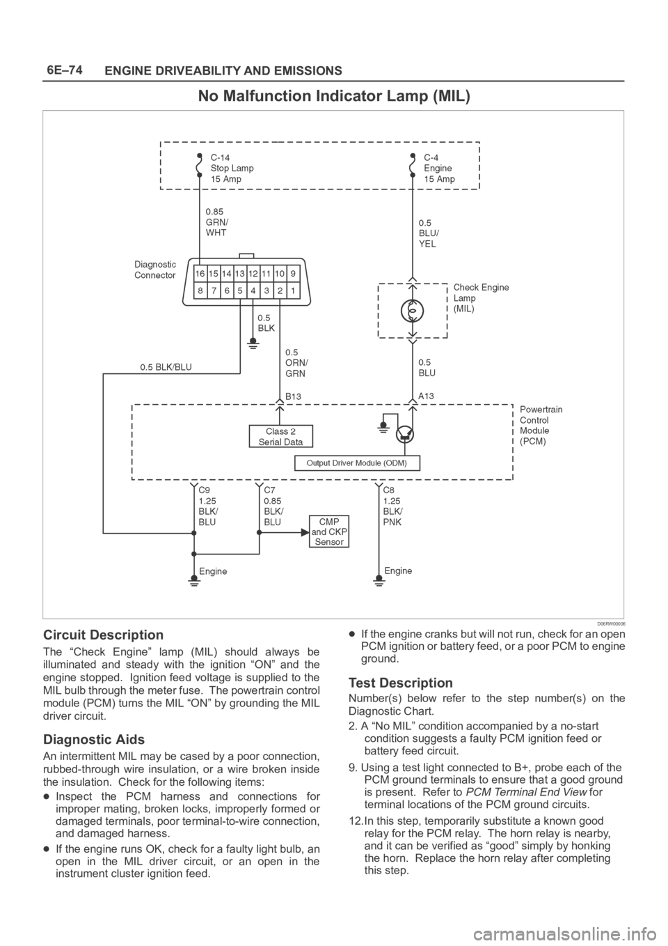
No Malfunction Indicator Lamp (MIL)
D06RW00006
Circuit Description
The “Check Engine” lamp (MIL) should always be
illuminated and steady with the ignition “ON” and the
engine stopped. Ignition feed voltage is supplied to the
MIL bulb through the meter fuse. The powertrain control
module (PCM) turns the MIL “ON” by grounding the MIL
driver circuit.
Diagnostic Aids
An intermittent MIL may be cased by a poor connection,
rubbed-through wire insulation, or a wire broken inside
the insulation. Check for the following items:
Inspect the PCM harness and connections for
improper mating, broken locks, improperly formed or
damaged terminals, poor terminal-to-wire connection,
and damaged harness.
If the engine runs OK, check for a faulty light bulb, an
open in the MIL driver circuit, or an open in the
instrument cluster ignition feed.
If the engine cranks but will not run, check for an open
PCM ignition or battery feed, or a poor PCM to engine
ground.
Test Description
Number(s) below refer to the step number(s) on the
Diagnostic Chart.
2. A “No MIL” condition accompanied by a no-start
condition suggests a faulty PCM ignition feed or
battery feed circuit.
9. Using a test light connected to B+, probe each of the
PCM ground terminals to ensure that a good ground
is present. Refer to
PCM Terminal End View for
terminal locations of the PCM ground circuits.
12.In this step, temporarily substitute a known good
relay for the PCM relay. The horn relay is nearby,
and it can be verified as “good” simply by honking
the horn. Replace the horn relay after completing
this step.
Page 4744 of 6000

6E–87 ENGINE DRIVEABILITY AND EMISSIONS
Fuel System Electrical Test
StepNo Ye s Va l u e ( s ) Action
9Check for short or open between the PCM and the fuel
pump relay.
Was a problem found?
—Verify repairGo to Step 10
101. Check the fuel pump relay circuit for a poor terminal
connection at the PCM.
2. If a problem is found, replace terminal as necessary.
Was a problem found?
—Verify repairGo to Step 11
11Replace the PCM.
IMPORTANT:The replacement PCM must be
programmed. Refer to
UBS 98model year Immobilizer
Workshop Manual.
Is the action complete?—Verify repair—
121. Reconnect the fuel pump relay.
2. Disconnect the fuel pump electrical connector at the
fuel tank.
3. Using a test light connected to ground, probe the
fuel pump feed wire (harness side).
4. Command the fuel pump “ON” with Tech 2.
Did the light illuminate for 2 seconds?
—Go to Step 15Go to Step 13
131. Honk the horn to verify that the horn relay is
functioning.
2. Substitute the horn relay for the fuel pump relay.
3. Leave the test light connected as in step 12.
4. Command the fuel pump “ON” with Tech 2.
Did the test light illuminate for 2 seconds when the fuel
pump was commanded “ON?”
—Go to Step 17Go to Step 14
141. Re-connect the horn relay in its proper location.
2. Check for a short circuit, blown fuse or open circuit
between the relay and the fuel tank.
Is the action complete?
—Verify repair—
151. With the fuel pump electrical connector at the fuel
tank disconnected, connect a test light between the
feed wire and the ground wire (harness side).
2. Command the fuel pump “ON” with Tech 2.
Did the test light illuminate for 2 seconds?
—Go to Step 18Go to Step 16
16Repair the open circuit in the fuel pump ground wire.
Is the action complete?
—Verify repair—
171. Re-connect the horn relay in its proper location.
2. Replace the fuel pump relay.
Is the action complete?
—Verify repair—
18Replace the fuel pump.
Is the action complete?
—Verify repair—
Page 4980 of 6000
6E–323 ENGINE DRIVEABILITY AND EMISSIONS
11. Connect the fuel filler fuse at the tank.
12. Connect the air breather hose at the tank.
TS23796
13. Fill the fuel tank with fuel.
14. Tighten the fuel filler cap.
15. Connect the negative battery cable.
Throttle Body (TB)
Removal Procedure
1. Disconnect the negative battery cable.
2. Drain the cooling system. Refer to
Cooling System.
3. Remove the accelerator cable assembly. Refer to
Accelerator Cable in Engine Speed Control System..
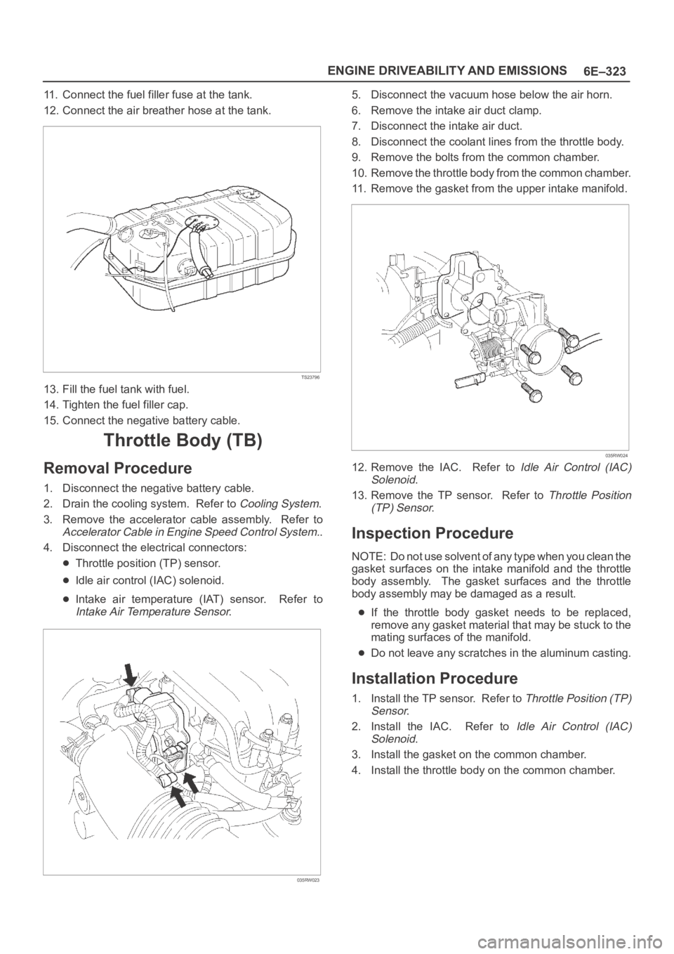
4. Disconnect the electrical connectors:
Throttle position (TP) sensor.
Idle air control (IAC) solenoid.
Intake air temperature (IAT) sensor. Refer to
Intake Air Temperature Sensor.
035RW023
5. Disconnect the vacuum hose below the air horn.
6. Remove the intake air duct clamp.
7. Disconnect the intake air duct.
8. Disconnect the coolant lines from the throttle body.
9. Remove the bolts from the common chamber.
10. Remove the throttle body from the common chamber.
11. Remove the gasket from the upper intake manifold.
035RW024
12. Remove the IAC. Refer to Idle Air Control (IAC)
Solenoid
.
13. Remove the TP sensor. Refer to
Throttle Position
(TP) Sensor
.
Inspection Procedure
NOTE: Do not use solvent of any type when you clean the
gasket surfaces on the intake manifold and the throttle
body assembly. The gasket surfaces and the throttle
body assembly may be damaged as a result.
If the throttle body gasket needs to be replaced,
remove any gasket material that may be stuck to the
mating surfaces of the manifold.
Do not leave any scratches in the aluminum casting.
Installation Procedure
1. Install the TP sensor. Refer to Throttle Position (TP)
Sensor
.
2. Install the IAC. Refer to
Idle Air Control (IAC)
Solenoid
.
3. Install the gasket on the common chamber.
4. Install the throttle body on the common chamber.
Page 5473 of 6000
6E–44
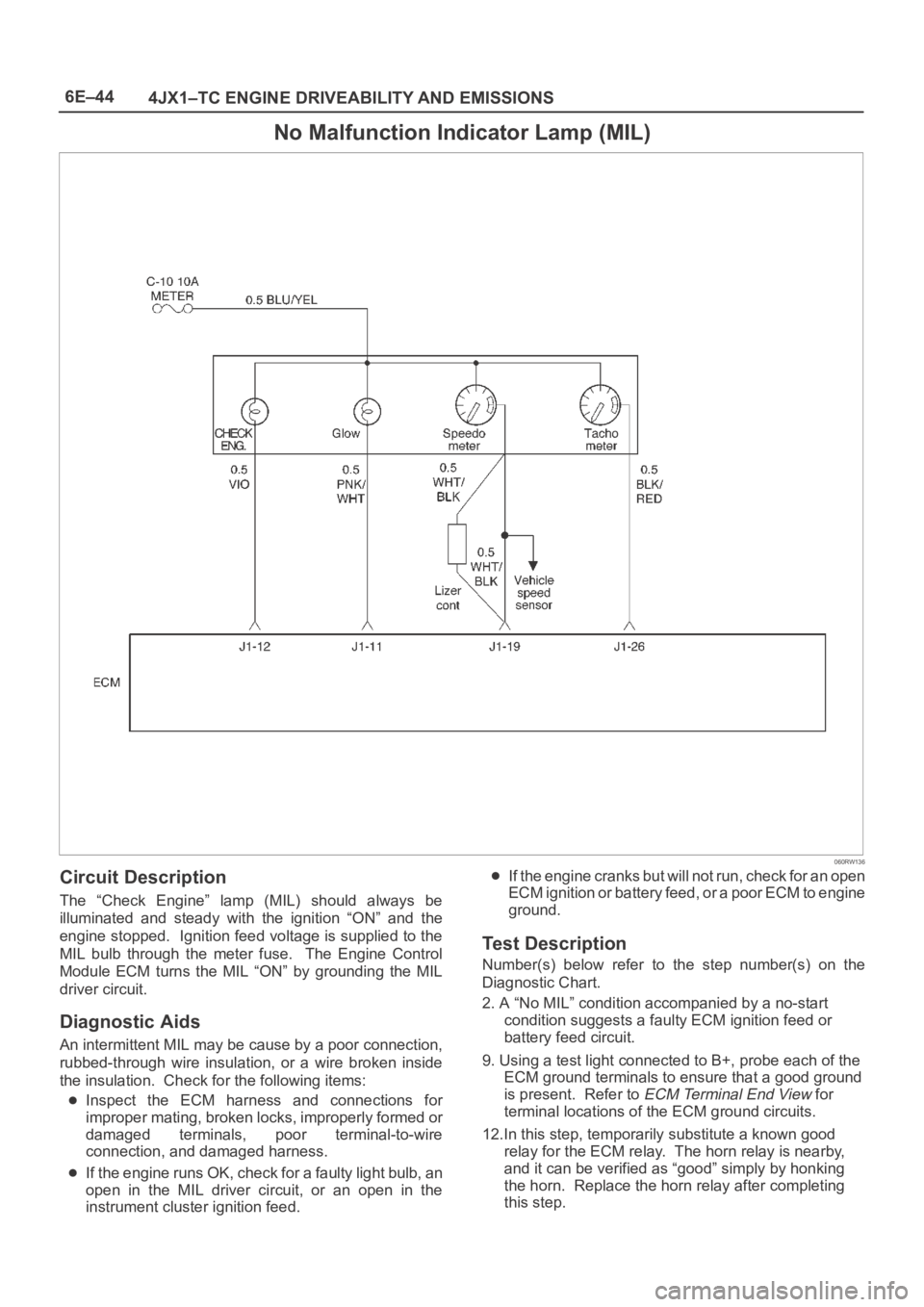
4JX1–TC ENGINE DRIVEABILITY AND EMISSIONS
No Malfunction Indicator Lamp (MIL)
060RW136
Circuit Description
The “Check Engine” lamp (MIL) should always be
illuminated and steady with the ignition “ON” and the
engine stopped. Ignition feed voltage is supplied to the
MIL bulb through the meter fuse. The Engine Control
Module ECM turns the MIL “ON” by grounding the MIL
driver circuit.
Diagnostic Aids
An intermittent MIL may be cause by a poor connection,
rubbed-through wire insulation, or a wire broken inside
the insulation. Check for the following items:
Inspect the ECM harness and connections for
improper mating, broken locks, improperly formed or
damaged terminals, poor terminal-to-wire
connection, and damaged harness.
If the engine runs OK, check for a faulty light bulb, an
open in the MIL driver circuit, or an open in the
instrument cluster ignition feed.
If the engine cranks but will not run, check for an open
ECM ignition or battery feed, or a poor ECM to engine
ground.
Test Description
Number(s) below refer to the step number(s) on the
Diagnostic Chart.
2. A “No MIL” condition accompanied by a no-start
condition suggests a faulty ECM ignition feed or
battery feed circuit.
9. Using a test light connected to B+, probe each of the
ECM ground terminals to ensure that a good ground
is present. Refer to
ECM Terminal End View for
terminal locations of the ECM ground circuits.
12.In this step, temporarily substitute a known good
relay for the ECM relay. The horn relay is nearby,
and it can be verified as “good” simply by honking
the horn. Replace the horn relay after completing
this step.