service indicator OPEL FRONTERA 1998 Owner's Guide
[x] Cancel search | Manufacturer: OPEL, Model Year: 1998, Model line: FRONTERA, Model: OPEL FRONTERA 1998Pages: 6000, PDF Size: 97 MB
Page 4697 of 6000
6E–40
ENGINE DRIVEABILITY AND EMISSIONS
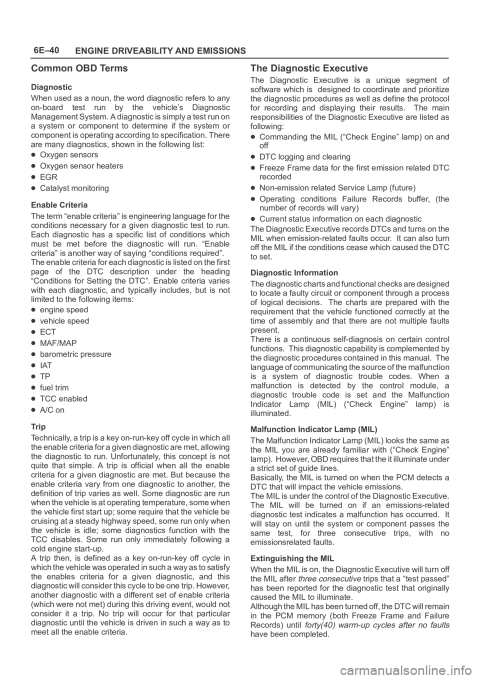
Common OBD Terms
Diagnostic
When used as a noun, the word diagnostic refers to any
on-board test run by the vehicle’s Diagnostic
Management System. A diagnostic is simply a test run on
a system or component to determine if the system or
component is operating according to specification. There
are many diagnostics, shown in the following list:
Oxygen sensors
Oxygen sensor heaters
EGR
Catalyst monitoring
Enable Criteria
The term “enable criteria” is engineering language for the
conditions necessary for a given diagnostic test to run.
Each diagnostic has a specific list of conditions which
must be met before the diagnostic will run. “Enable
criteria” is another way of saying “conditions required”.
The enable criteria for each diagnostic is listed on the first
page of the DTC description under the heading
“Conditions for Setting the DTC”. Enable criteria varies
with each diagnostic, and typically includes, but is not
limited to the following items:
engine speed
vehicle speed
ECT
MAF/MAP
barometric pressure
IAT
TP
fuel trim
TCC enabled
A/C on
Tr i p
Technically, a trip is a key on-run-key off cycle in which all
the enable criteria for a given diagnostic are met, allowing
the diagnostic to run. Unfortunately, this concept is not
quite that simple. A trip is official when all the enable
criteria for a given diagnostic are met. But because the
enable criteria vary from one diagnostic to another, the
definition of trip varies as well. Some diagnostic are run
when the vehicle is at operating temperature, some when
the vehicle first start up; some require that the vehicle be
cruising at a steady highway speed, some run only when
the vehicle is idle; some diagnostics function with the
TCC disables. Some run only immediately following a
cold engine start-up.
A trip then, is defined as a key on-run-key off cycle in
which the vehicle was operated in such a way as to satisfy
the enables criteria for a given diagnostic, and this
diagnostic will consider this cycle to be one trip. However,
another diagnostic with a different set of enable criteria
(which were not met) during this driving event, would not
consider it a trip. No trip will occur for that particular
diagnostic until the vehicle is driven in such a way as to
meet all the enable criteria.
The Diagnostic Executive
The Diagnostic Executive is a unique segment of
software which is designed to coordinate and prioritize
the diagnostic procedures as well as define the protocol
for recording and displaying their results. The main
responsibilities of the Diagnostic Executive are listed as
following:
Commanding the MIL (“Check Engine” lamp) on and
off
DTC logging and clearing
Freeze Frame data for the first emission related DTC
recorded
Non-emission related Service Lamp (future)
Operating conditions Failure Records buffer, (the
number of records will vary)
Current status information on each diagnostic
The Diagnostic Executive records DTCs and turns on the
MIL when emission-related faults occur. It can also turn
off the MIL if the conditions cease which caused the DTC
to set.
Diagnostic Information
The diagnostic charts and functional checks are designed
to locate a faulty circuit or component through a process
of logical decisions. The charts are prepared with the
requirement that the vehicle functioned correctly at the
time of assembly and that there are not multiple faults
present.
There is a continuous self-diagnosis on certain control
functions. This diagnostic capability is complemented by
the diagnostic procedures contained in this manual. The
language of communicating the source of the malfunction
is a system of diagnostic trouble codes. When a
malfunction is detected by the control module, a
diagnostic trouble code is set and the Malfunction
Indicator Lamp (MIL) (“Check Engine” lamp) is
illuminated.
Malfunction Indicator Lamp (MIL)
The Malfunction Indicator Lamp (MIL) looks the same as
the MIL you are already familiar with (“Check Engine”
lamp). However, OBD requires that the it illuminate under
a strict set of guide lines.
Basically, the MIL is turned on when the PCM detects a
DTC that will impact the vehicle emissions.
The MIL is under the control of the Diagnostic Executive.
The MIL will be turned on if an emissions-related
diagnostic test indicates a malfunction has occurred. It
will stay on until the system or component passes the
same test, for three consecutive trips, with no
emissionsrelated faults.
Extinguishing the MIL
When the MIL is on, the Diagnostic Executive will turn off
the MIL after
three consecutive trips that a “test passed”
has been reported for the diagnostic test that originally
caused the MIL to illuminate.
Although the MIL has been turned off, the DTC will remain
in the PCM memory (both Freeze Frame and Failure
Records) until
forty(40) warm-up cycles after no faults
have been completed.
Page 4699 of 6000
6E–42
ENGINE DRIVEABILITY AND EMISSIONS
Intermittent Malfunction Indicator Lamp
In the case of an “intermittent” fault, the MIL (“Check
Engine” lamp) may illuminate and then (after three trips)
go “OFF”. However, the corresponding diagnostic trouble
code will be stored in the memory. When unexpected
diagnostic trouble codes appear, check for an intermittent
malfunction.
A diagnostic trouble code may reset. Consult the
“Diagnostic Aids” associated with the diagnostic trouble
code. A physical inspection of the applicable sub-system
most often will resolve the problem.
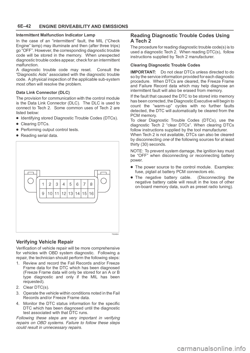
Data Link Connector (DLC)
The provision for communication with the control module
is the Data Link Connector (DLC). The DLC is used to
connect to Tech 2. Some common uses of Tech 2 are
listed below:
Identifying stored Diagnostic Trouble Codes (DTCs).
Clearing DTCs.
Performing output control tests.
Reading serial data.
TS24064
Verifying Vehicle Repair
Verification of vehicle repair will be more comprehensive
for vehicles with OBD system diagnostic. Following a
repair, the technician should perform the following steps:
1. Review and record the Fail Records and/or Freeze
Frame data for the DTC which has been diagnosed
(Freeze Frame data will only be stored for an A or B
type diagnostic and only if the MIL has been
requested).
2. Clear DTC(s).
3. Operate the vehicle within conditions noted in the Fail
Records and/or Freeze Frame data.
4. Monitor the DTC status information for the specific
DTC which has been diagnosed until the diagnostic
test associated with that DTC runs.
Following these steps are very important in verifying
repairs on OBD systems. Failure to follow these steps
could result in unnecessary repairs.
Reading Diagnostic Trouble Codes Using
A Tech 2
The procedure for reading diagnostic trouble code(s) is to
used a diagnostic Tech 2. When reading DTC(s), follow
instructions supplied by Tech 2 manufacturer.
Clearing Diagnostic Trouble Codes
IMPORTANT:Do not clear DTCs unless directed to do
so by the service information provided for each diagnostic
procedure. When DTCs are cleared, the Freeze Frame
and Failure Record data which may help diagnose an
intermittent fault will also be erased from memory.
If the fault that caused the DTC to be stored into memory
has been corrected, the Diagnostic Executive will begin to
count the “warm-up” cycles with no further faults
detected, the DTC will automatically be cleared from the
PCM memory.
To clear Diagnostic Trouble Codes (DTCs), use the
diagnostic Tech 2 “clear DTCs”. When clearing DTCs
follow instructions supplied by the tool manufacturer.
When Tech 2 is not available, DTCs can also be cleared
by disconnecting
one of the following sources for at least
thirty (30) seconds.
NOTE: To prevent system damage, the ignition key must
be “OFF” when disconnecting or reconnecting battery
power.
The power source to the control module. Examples:
fuse, pigtail at battery PCM connectors etc.
The negative battery cable. (Disconnecting the
negative battery cable will result in the loss of other
on-board memory data, such as preset radio tuning).
Page 4710 of 6000
6E–53 ENGINE DRIVEABILITY AND EMISSIONS
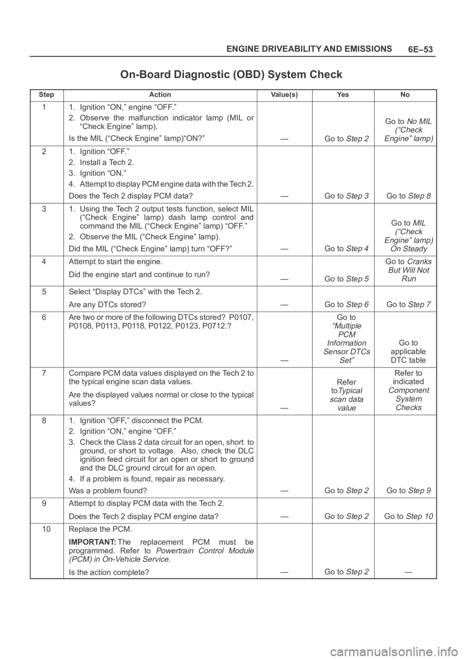
On-Board Diagnostic (OBD) System Check
StepActionVa l u e ( s )Ye sNo
11. Ignition “ON,” engine “OFF.”
2. Observe the malfunction indicator lamp (MIL or
“Check Engine” lamp).
Is the MIL (“Check Engine” lamp)“ON?”
—Go to Step 2
Go to No MIL
(“Check
Engine” lamp)
21. Ignition “OFF.”
2. Install a Tech 2.
3. Ignition “ON.”
4. Attempt to display PCM engine data with the Tech 2.
Does the Tech 2 display PCM data?
—Go to Step 3Go to Step 8
31. Using the Tech 2 output tests function, select MIL
(“Check Engine” lamp) dash lamp control and
command the MIL (“Check Engine” lamp) “OFF.”
2. Observe the MIL (“Check Engine” lamp).
Did the MIL (“Check Engine” lamp) turn “OFF?”
—Go to Step 4
Go to MIL
(“Check
Engine” lamp)
On Steady
4Attempt to start the engine.
Did the engine start and continue to run?
—Go to Step 5
Go to Cranks
But Will Not
Run
5Select “Display DTCs” with the Tech 2.
Are any DTCs stored?
—Go to Step 6Go to Step 7
6Are two or more of the following DTCs stored? P0107,
P0108, P0113, P0118, P0122, P0123, P0712.?
—
Go to
“Multiple
PCM
Information
Sensor DTCs
Set”
Go to
applicable
DTC table
7Compare PCM data values displayed on the Tech 2 to
the typical engine scan data values.
Are the displayed values normal or close to the typical
values?
—
Refer
to
Ty p i c a l
scan data
value
Refer to
indicated
Component
System
Checks
81. Ignition “OFF,” disconnect the PCM.
2. Ignition “ON,” engine “OFF.”
3. Check the Class 2 data circuit for an open, short to
ground, or short to voltage. Also, check the DLC
ignition feed circuit for an open or short to ground
and the DLC ground circuit for an open.
4. If a problem is found, repair as necessary.
Was a problem found?
—Go to Step 2Go to Step 9
9Attempt to display PCM data with the Tech 2.
Does the Tech 2 display PCM engine data?
—Go to Step 2Go to Step 10
10Replace the PCM.
IMPORTANT:The replacement PCM must be
programmed. Refer to
Powertrain Control Module
(PCM) in On-Vehicle Service.
Is the action complete?—Go to Step 2—
Page 4733 of 6000
6E–76
ENGINE DRIVEABILITY AND EMISSIONS
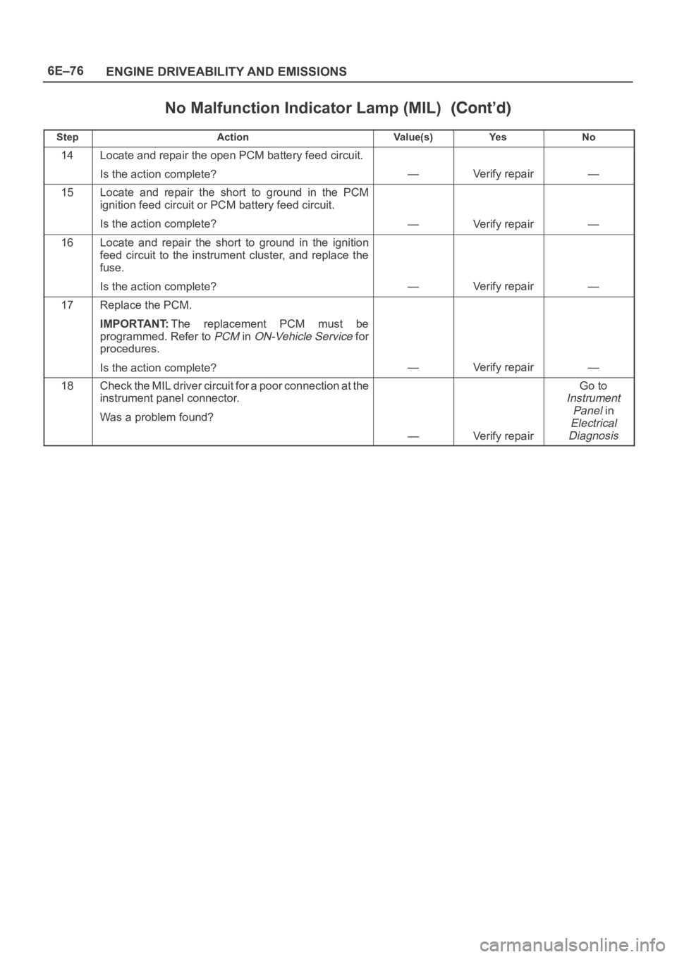
No Malfunction Indicator Lamp (MIL)
StepNo Ye s Va l u e ( s ) Action
14Locate and repair the open PCM battery feed circuit.
Is the action complete?
—Verify repair—
15Locate and repair the short to ground in the PCM
ignition feed circuit or PCM battery feed circuit.
Is the action complete?
—Verify repair—
16Locate and repair the short to ground in the ignition
feed circuit to the instrument cluster, and replace the
fuse.
Is the action complete?
—Verify repair—
17Replace the PCM.
IMPORTANT:The replacement PCM must be
programmed. Refer to
PCM in ON-Vehicle Service for
procedures.
Is the action complete?
—Verify repair—
18Check the MIL driver circuit for a poor connection at the
instrument panel connector.
Was a problem found?
—Verify repair
Go to
Instrument
Panel
in
Electrical
Diagnosis
Page 4735 of 6000
6E–78
ENGINE DRIVEABILITY AND EMISSIONS
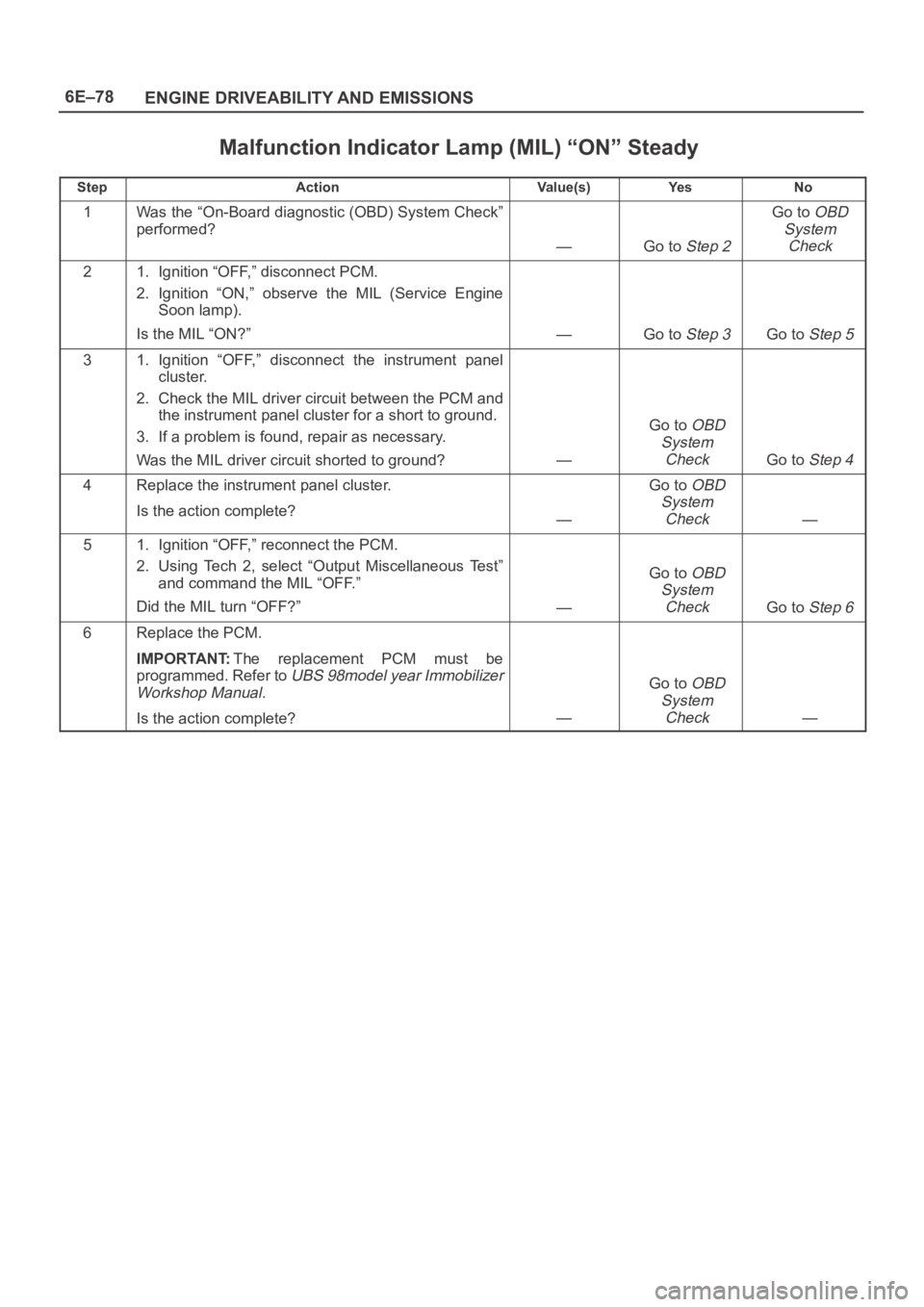
Malfunction Indicator Lamp (MIL) “ON” Steady
StepActionVa l u e ( s )Ye sNo
1Was the “On-Board diagnostic (OBD) System Check”
performed?
—Go to Step 2
Go to OBD
System
Check
21. Ignition “OFF,” disconnect PCM.
2. Ignition “ON,” observe the MIL (Service Engine
Soon lamp).
Is the MIL “ON?”
—Go to Step 3Go to Step 5
31. Ignition “OFF,” disconnect the instrument panel
cluster.
2. Check the MIL driver circuit between the PCM and
the instrument panel cluster for a short to ground.
3. If a problem is found, repair as necessary.
Was the MIL driver circuit shorted to ground?
—
Go to OBD
System
Check
Go to Step 4
4Replace the instrument panel cluster.
Is the action complete?
—
Go to OBD
System
Check
—
51. Ignition “OFF,” reconnect the PCM.
2. Using Tech 2, select “Output Miscellaneous Test”
and command the MIL “OFF.”
Did the MIL turn “OFF?”
—
Go to OBD
System
Check
Go to Step 6
6Replace the PCM.
IMPORTANT:The replacement PCM must be
programmed. Refer to
UBS 98model year Immobilizer
Workshop Manual.
Is the action complete?—
Go to OBD
System
Check
—
Page 4761 of 6000
6E–104
ENGINE DRIVEABILITY AND EMISSIONS
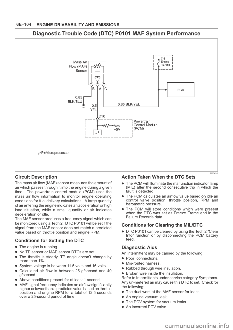
Diagnostic Trouble Code (DTC) P0101 MAF System Performance
D06RW103
Circuit Description
The mass air flow (MAF) sensor measures the amount of
air which passes through it into the engine during a given
time. The powertrain control module (PCM) uses the
mass air flow information to monitor engine operating
conditions for fuel delivery calculations. A large quantity
of air entering the engine indicates an acceleration or high
load situation, while a small quantity or air indicates
deceleration or idle.
The MAF sensor produces a frequency signal which can
be monitored using a Tech 2. DTC P0101 will be set if the
signal from the MAF sensor does not match a predicted
value based on throttle position and engine RPM.
Conditions for Setting the DTC
The engine is running.
No TP sensor or MAP sensor DTCs are set.
The throttle is steady, TP angle doesn’t change by
more than 1%.
System voltage is between 11.5 volts and 16 volts.
Calculated air flow is between 25 g/second and 40
g/second.
Above conditions present for at least 1 second.
MAF signal frequency indicates an airflow significantly
higher or lower than a predicted value based on throttle
position and engine RPM for a total of 12.5 seconds
over a 25-second period of time.
Action Taken When the DTC Sets
The PCM will illuminate the malfunction indicator lamp
(MIL) after the second consecutive trip in which the
fault is detected.
The PCM calculates an airflow value based on idle air
control valve position, throttle position, RPM and
barometric pressure.
The PCM will store conditions which were present
when the DTC was set as Freeze Frame and in the
Failure Records data.
Conditions for Clearing the MIL/DTC
DTC P0101 can be cleared by using the Tech 2 “Clear
Info” function or by disconnecting the PCM battery
feed.
Diagnostic Aids
An intermittent may be caused by the following:
Poor connections.
Mis-routed harness.
Rubbed through wire insulation.
Broken wire inside the insulation.
Refer to Intermittents under service category Symptoms.
Any un-metered air may cause this DTC to set. Check for
the following:
The duct work at the MAF sensor for leaks.
An engine vacuum leak.
The PCV system for vacuum leaks.
An incorrect PCV valve.
Page 4919 of 6000
6E–262
ENGINE DRIVEABILITY AND EMISSIONS
Symptom Diagnosis
Preliminary Checks
Before using this section, perform the “On-Board
Diagnostic (OBD) System Check” and verify all of the
following items:
The powertrain control module (PCM) and malfunction
indicator lamp (MIL) (Service Engine Soon lamp) are
operating correctly.
There are no DTC(s) stored.
Tech 2 data is within normal operating range. Refer to
Typical Scan Data Values.
Verify the customer complaint and locate the correct
symptom in the table of contents. Perform the
procedure included in the symptom chart.
Visual/Physical Check
Several of the symptom procedures call for a careful
visual/physical check. This can lead to correcting a
problem without further checks and can save valuable
time.
This check should include the following items:
PCM grounds for cleanliness, tightness and proper
location.
Vacuum hoses for splits, kinks, and proper
connections, as shown on the “Vehicle Emission
Control Information” label. Check thoroughly for any
type of leak or restriction.
Air intake ducts for collapsed or damaged areas.
Air leaks at throttle body mounting area, mass air flow
(MAF) sensor and intake manifold sealing surfaces.
Ignition wires for cracking, hardness, and carbon
tracking.
Wiring for proper connections, pinches and cuts.
Intermittents
IMPORTANT:An intermittent problem may or may not
turn on the malfunction indicator lamp (MIL) or store a
DTC. DO NOT use the Diagnostic Trouble Code (DTC)
charts for intermittent problems. The fault must be
present to locate the problem.
Most intermittent problems are caused by faulty electrical
connections or wiring. Perform a careful visual/physical
check for the following conditions:
Poor mating of the connector halves or a terminal not
fully seated in the connector (backed out).
Improperly formed or damaged terminal.
All connector terminals in the problem circuit should be
carefully checked for proper contact tension.
Poor terminal-to-wire connection. This requires
removing the terminal from the connector body to
check.
Road test the vehicle with a J 39200 Digital Multimeter
connected to a suspected circuit. An abnormal voltage
when the malfunction occurs is a good indication that
there is a fault in the circuit being monitored.
Use Tech 2 to help detect intermittent conditions. Tech 2s
have several features that can be used to locate anintermittent condition. Use the following feature to find
intermittent faults:
Using Tech 2’s “Freeze Frame” buffer or “Failure
Records” buffer can aid in locating an intermittent
condition. Review and record the information in the
freeze frame or failure record associated with the
intermittent DTC being diagnosed. The vehicle can be
driven within the conditions that were present when the
DTC originally set.
To check for loss of diagnostic code memory, disconnect
the MAP sensor and idle the engine until the MIL (Service
Engine Soon lamp) comes on. DTC P0107 should be
stored and kept in memory when the ignition is turned
“OFF.” If not, the PCM is faulty. When this test is
completed, make sure that you clear the DTC P0107 from
memory.
An intermittent MIL (Service Engine Soon lamp) with no
stored DTC may be caused by the following:
Ignition coil shorted to ground and arcing at ignition
wires or plugs.
MIL (Service Engine Soon lamp) wire to PCM shorted
to ground.
Poor PCM grounds. Refer to the PCM wiring
diagrams.
Check for improper installation of electrical options such
as lights, cellular phones, etc. Route ignition coil wiring
away from the ignition coils. Check all wires from the
PCM to the ignition coil for poor connections.
Check for an open diode across the A/C compressor
clutch and check for other open diodes (refer to wiring
diagrams in
Electrical Diagnosis).
If problem has not been found, refer to
PCM Connector
Symptom
tables.
Page 4955 of 6000
6E–298
ENGINE DRIVEABILITY AND EMISSIONS
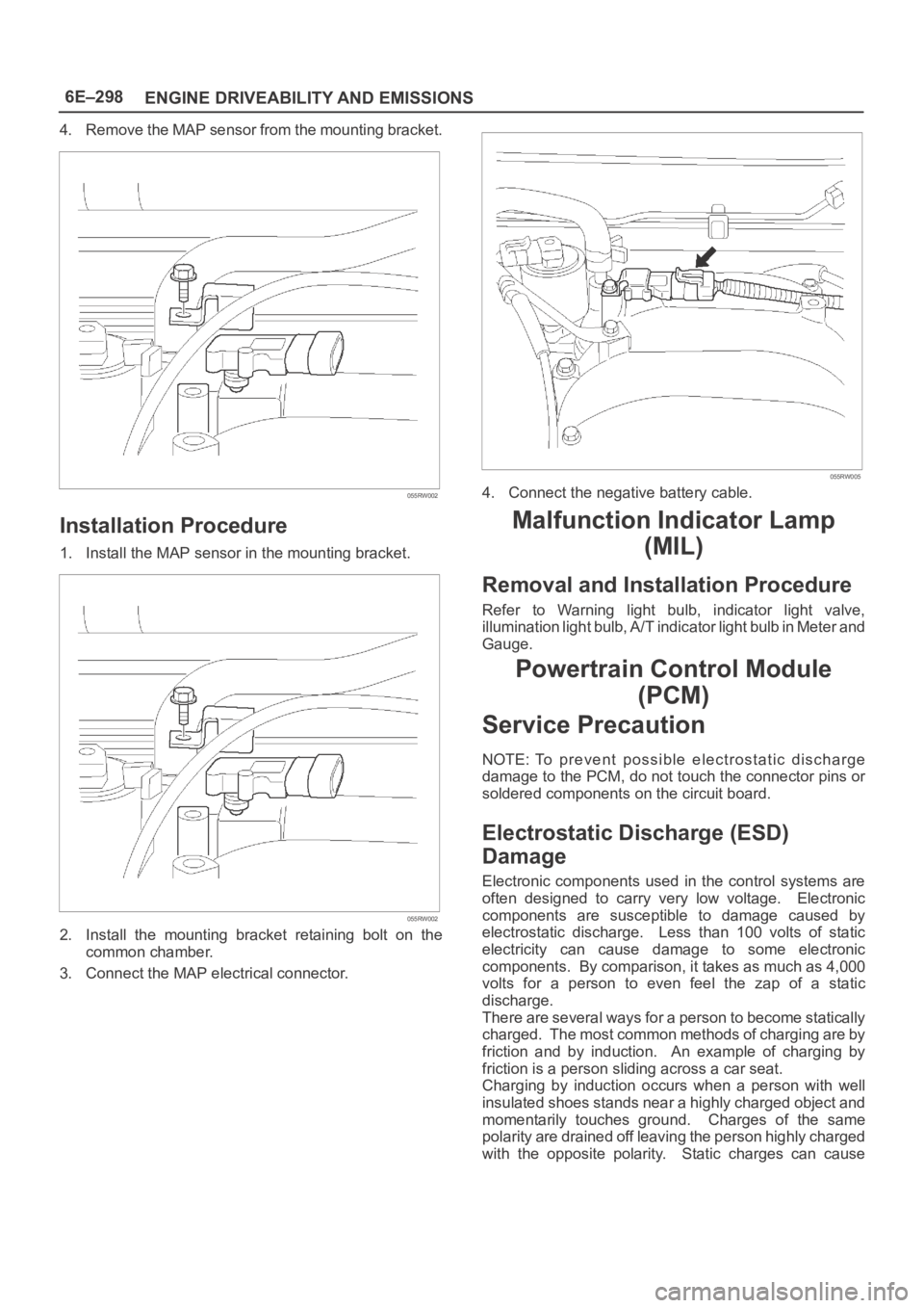
4. Remove the MAP sensor from the mounting bracket.
055RW002
Installation Procedure
1. Install the MAP sensor in the mounting bracket.
055RW002
2. Install the mounting bracket retaining bolt on the
common chamber.
3. Connect the MAP electrical connector.
055RW005
4. Connect the negative battery cable.
Malfunction Indicator Lamp
(MIL)
Removal and Installation Procedure
Refer to Warning light bulb, indicator light valve,
illumination light bulb, A/T indicator light bulb in Meter and
Gauge.
Powertrain Control Module
(PCM)
Service Precaution
NOTE: To prevent possible electrostatic discharge
damage to the PCM, do not touch the connector pins or
soldered components on the circuit board.
Electrostatic Discharge (ESD)
Damage
Electronic components used in the control systems are
often designed to carry very low voltage. Electronic
components are susceptible to damage caused by
electrostatic discharge. Less than 100 volts of static
electricity can cause damage to some electronic
components. By comparison, it takes as much as 4,000
volts for a person to even feel the zap of a static
discharge.
There are several ways for a person to become statically
charged. The most common methods of charging are by
friction and by induction. An example of charging by
friction is a person sliding across a car seat.
Charging by induction occurs when a person with well
insulated shoes stands near a highly charged object and
momentarily touches ground. Charges of the same
polarity are drained off leaving the person highly charged
with the opposite polarity. Static charges can cause
Page 4996 of 6000
6E–339 ENGINE DRIVEABILITY AND EMISSIONS
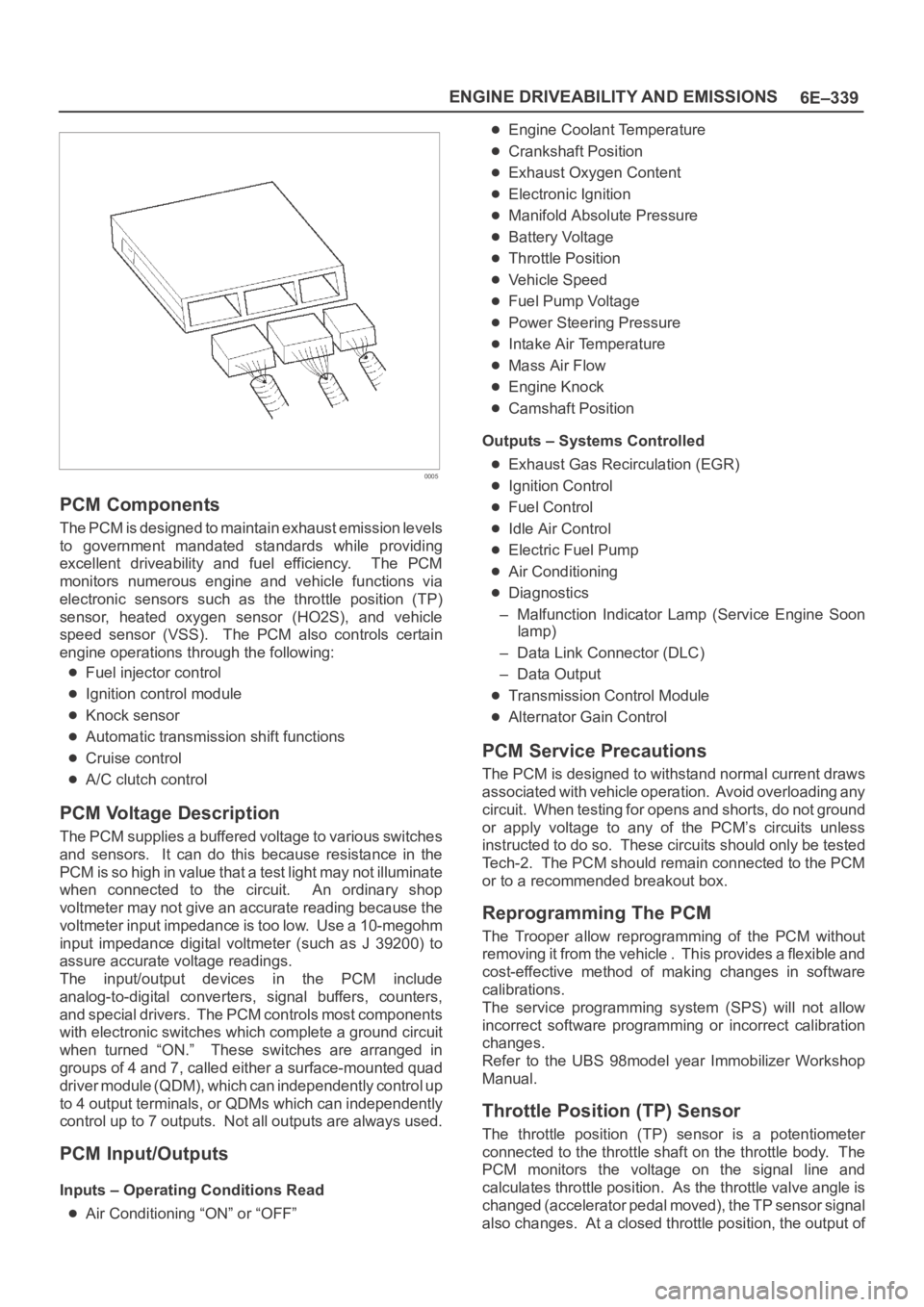
0005
PCM Components
The PCM is designed to maintain exhaust emission levels
to government mandated standards while providing
excellent driveability and fuel efficiency. The PCM
monitors numerous engine and vehicle functions via
electronic sensors such as the throttle position (TP)
sensor, heated oxygen sensor (HO2S), and vehicle
speed sensor (VSS). The PCM also controls certain
engine operations through the following:
Fuel injector control
Ignition control module
Knock sensor
Automatic transmission shift functions
Cruise control
A/C clutch control
PCM Voltage Description
The PCM supplies a buffered voltage to various switches
and sensors. It can do this because resistance in the
PCM is so high in value that a test light may not illuminate
when connected to the circuit. An ordinary shop
voltmeter may not give an accurate reading because the
voltmeter input impedance is too low. Use a 10-megohm
input impedance digital voltmeter (such as J 39200) to
assure accurate voltage readings.
The input/output devices in the PCM include
analog-to-digital converters, signal buffers, counters,
and special drivers. The PCM controls most components
with electronic switches which complete a ground circuit
when turned “ON.” These switches are arranged in
groups of 4 and 7, called either a surface-mounted quad
driver module (QDM), which can independently control up
to 4 output terminals, or QDMs which can independently
control up to 7 outputs. Not all outputs are always used.
PCM Input/Outputs
Inputs – Operating Conditions Read
Air Conditioning “ON” or “OFF”
Engine Coolant Temperature
Crankshaft Position
Exhaust Oxygen Content
Electronic Ignition
Manifold Absolute Pressure
Battery Voltage
Throttle Position
Vehicle Speed
Fuel Pump Voltage
Power Steering Pressure
Intake Air Temperature
Mass Air Flow
Engine Knock
Camshaft Position
Outputs – Systems Controlled
Exhaust Gas Recirculation (EGR)
Ignition Control
Fuel Control
Idle Air Control
Electric Fuel Pump
Air Conditioning
Diagnostics
– Malfunction Indicator Lamp (Service Engine Soon
lamp)
– Data Link Connector (DLC)
– Data Output
Transmission Control Module
Alternator Gain Control
PCM Service Precautions
The PCM is designed to withstand normal current draws
associated with vehicle operation. Avoid overloading any
circuit. When testing for opens and shorts, do not ground
or apply voltage to any of the PCM’s circuits unless
instructed to do so. These circuits should only be tested
Tech-2. The PCM should remain connected to the PCM
or to a recommended breakout box.
Reprogramming The PCM
The Trooper allow reprogramming of the PCM without
removing it from the vehicle . This provides a flexible and
cost-effective method of making changes in software
calibrations.
The service programming system (SPS) will not allow
incorrect software programming or incorrect calibration
changes.
Refer to the UBS 98model year Immobilizer Workshop
Manual.
Throttle Position (TP) Sensor
The throttle position (TP) sensor is a potentiometer
connected to the throttle shaft on the throttle body. The
PCM monitors the voltage on the signal line and
calculates throttle position. As the throttle valve angle is
changed (accelerator pedal moved), the TP sensor signal
also changes. At a closed throttle position, the output of
Page 5404 of 6000
ENGINE ELECTRICAL 6D – 1
ENGINE ELECTRICAL
CONTENTS
Battery . . . . . . . . . . . . . . . . . . . . . . . . . . . . 6D–1
General Description . . . . . . . . . . . . . . . . 6D–1
Diagnosis . . . . . . . . . . . . . . . . . . . . . . . . 6D–1
On Vehicle Service . . . . . . . . . . . . . . . . . 6D–3
Main Data and Specification . . . . . . . . . . 6D–4
Starting System . . . . . . . . . . . . . . . . . . . . . 6D–5
General Description . . . . . . . . . . . . . . . . 6D–5
On Vehicle Service . . . . . . . . . . . . . . . . . 6D–7
Starter . . . . . . . . . . . . . . . . . . . . . . . . . . 6D–7
Unit Repair . . . . . . . . . . . . . . . . . . . . . . . 6D–8Charging System . . . . . . . . . . . . . . . . . . . . 6D–15
General Description . . . . . . . . . . . . . . . . 6D–15
Diagnosis . . . . . . . . . . . . . . . . . . . . . . . . 6D–16
Unit Repair . . . . . . . . . . . . . . . . . . . . . . . 6D–17
Main Data and Specification . . . . . . . . . . 6D–22
QOS4 Preheating System . . . . . . . . . . . . . . 6D–23
General Description . . . . . . . . . . . . . . . . 6D–23
System Diagram . . . . . . . . . . . . . . . . . . . 6D–23
Inspection of QOS4 System Operation . . 6D–24
BATTERY
GENERAL DESCRIPTION
DIAGNOSIS
There are six battery fluid caps at the top of the battery.
These are covered by a paper label.
The battery is completely sealed except for the six
small vent holes at the side. These vent holes permit
the escape of small amounts of gas generated by the
battery.
This type of battery has the following advantages over
conventional batteries:1. There is no need to add water during the entire
service life of the battery.
2. The battery protects itself against overcharging.
The battery will refuse to accept an excessive
charge.
(A conventional battery will accept an excessive
charge, resulting in gassing and loss of battery
fluid.)
3. The battery is much less vulnerable to self-
discharge than a conventional type battery.
1. VISUAL INSPECTION (Step 1)
Inspect the battery for obvious physical damage, such
as a cracked or broken case, which would permit
electrolyte loss.
Replace the battery if obvious physical damage is
discovered during inspection.
Check for any other physical damage and correct it as
necessary. If not, proceed to Step 2.
2. HYDROMETER CHECK (Step 2)
There is a built-in hydrometer (Charge test indicator) at
the top of the battery. It is designed to be used during
diagnostic procedures.
Before trying to read the hydrometer, carefully clean the
upper battery surface.
If your work area is poorly lit, additional light may be
necessary to read the hydrometer.
a. BLUE RING OR DOT VISIBLE – Go to Step 4.
b. BLUE RING OR DOT NOT VISIBLE – Go to
Step 3.3. FLUID LEVEL CHECK (Step 3)
The fluid level should be between the upper level line
and lower level line on side of the battery.
a. CORRECT FLUID LEVEL – Charge the battery.
b. BELOW LOWER LEVEL – Replace battery.
4. VOLTAGE CHECK (Step 4)
(1) Put voltmeter test leads to battery terminals.
a. VOLTAGE IS 12.4V OR ABOVE – Go to Step 5.
b. VOLTAGE IS UNDER 12.4V – Go to procedure
(2) below.
(2) Determine fast charge amperage from
specification. (See Main Data and Specifications in
this section.)
Fast charge battery for 30 minutes at amperage
rate no higher than specified value.
Take voltage and amperage readings after charge.
a. VOLTAGE IS ABOVE 16V AT BELOW 1/3 OF
AMPERAGE RATE – Replace battery.