2.2 OPEL FRONTERA 1998 Repair Manual
[x] Cancel search | Manufacturer: OPEL, Model Year: 1998, Model line: FRONTERA, Model: OPEL FRONTERA 1998Pages: 6000, PDF Size: 97 MB
Page 4597 of 6000
6B–4
ENGINE COOLING
NOTE: Antifreeze solution + Water = Total cooling
system capacity.
Total Cooling System Capacity
M/T 8.8Lit (2.32Us gal)
A/T 8.4Lit (2.22Us gal)
B06RW002
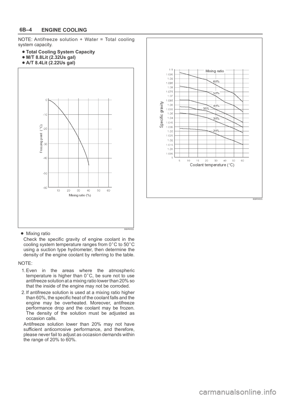
Mixing ratio
Check the specific gravity of engine coolant in the
cooling system temperature ranges from 0
C to 50C
using a suction type hydrometer, then determine the
density of the engine coolant by referring to the table.
NOTE:
1. Even in the areas where the atmospheric
temperature is higher than 0
C, be sure not to use
antifreeze solution at a mixing ratio lower than 20% so
that the inside of the engine may not be corroded.
2. If antifreeze solution is used at a mixing ratio higher
than 60%, the specific heat of the coolant falls and the
engine may be overheated. Moreover, antifreeze
performance drop and the coolant may be frozen.
The density of the solution must be adjusted as
occasion calls.
Antifreeze solution lower than 20% may not have
sufficient anticorrosive performance, and therefore,
please never fail to adjust as occasion demands within
the range of 20% to 60%.
B06RW003
Page 4605 of 6000
6B–12
ENGINE COOLING
Drive Belt and Cooling Fan
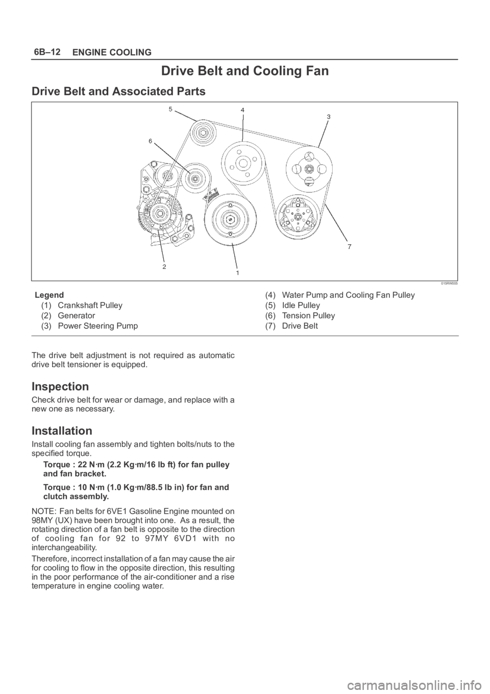
Drive Belt and Associated Parts
015RW005
Legend
(1) Crankshaft Pulley
(2) Generator
(3) Power Steering Pump(4) Water Pump and Cooling Fan Pulley
(5) Idle Pulley
(6) Tension Pulley
(7) Drive Belt
The drive belt adjustment is not required as automatic
drive belt tensioner is equipped.
Inspection
Check drive belt for wear or damage, and replace with a
new one as necessary.
Installation
Install cooling fan assembly and tighten bolts/nuts to the
specified torque.
Torque : 22 Nꞏm (2.2 Kgꞏm/16 lb ft) for fan pulley
and fan bracket.
Torque : 10 Nꞏm (1.0 Kgꞏm/88.5 lb in) for fan and
clutch assembly.
NOTE: Fan belts for 6VE1 Gasoline Engine mounted on
98MY (UX) have been brought into one. As a result, the
rotating direction of a fan belt is opposite to the direction
o f c o o l i n g f a n f o r 9 2 t o 9 7 M Y 6 V D 1 w i t h n o
interchangeability.
Therefore, incorrect installation of a fan may cause the air
for cooling to flow in the opposite direction, this resulting
in the poor performance of the air-conditioner and a rise
temperature in engine cooling water.
Page 4677 of 6000

6E–20
ENGINE DRIVEABILITY AND EMISSIONS
PCM Pinout Table, 32-Way White Connector – Row “C” (For EC)
TS23345
PINPIN FunctionWire ColorIGN ONENG RUNRefer To
C1Injector Cylinder #4GRN/REDB+B+General Description and
Operation, Fuel Injector
C2Shift “B” SolenoidBRN/BLK0.0 V0.0 VAutomatic Transmission
(4L30E)
C3Injector Cylinder #6GRN/YELB+B+General Description and
Operation, Fuel Injector
C4Ignition Control (IC)
Cylinder #1RED0.0 V0.1 VGeneral Description and
Operation, Fuel Injector
C5Crankshaft Position
Sensor, “A” CircuitYEL0.3 V to 5 V2.2 VGeneral Description and
Operation, Crankshaft
Position Sensor
C6Not Used————
C7PCM GroundYEL0.0 V0.0 VChassis Electrical
C8PCM GroundBLK/PNK0.0 V0.0 VChassis Electrical
C9PCM GroundBLK/BLU0.0 V0.0 VChassis Electrical
C10TachometerBLK/RED8.8 V10.0 V
(at idle)Chassis Electrical
C11Variable Intake ManifoldYEL/BLK0.0 VB+ (rpm
3600 over)Manual Transmission
C12Alternator Control GainWHT/BLU10.5 VB+Chassis Electrical
C13Fuel PWMBLU/PNKB+B+—
C14Bank 2 HO2S 1 HighPNK0.4 V0.1-0.9 VGeneral Description and
Operation, Fuel HO2S 1
C15Bank 2 HO2S 1 LowBLU0.0 V0.1 VGeneral Description and
Operation, Fuel HO2S 1
C16Not Used————
Page 4678 of 6000

6E–21 ENGINE DRIVEABILITY AND EMISSIONS
PCM Pinout Table, 32-Way White Connector – Row “C” (For except EC)
TS23345
PINPIN FunctionWire ColorIGN ONENG RUNRefer To
C1Injector Cylinder #4GRN/REDB+B+General Description and
Operation, Fuel Injector
C2Shift “B” SolenoidBRN/BLK0.0 V0.0 VAutomatic Transmission
(4L30E)
C3Injector Cylinder #6GRN/YELB+B+General Description and
Operation, Fuel Injector
C4Ignition Control (IC)
Cylinder #1RED0.0 V0.1 VGeneral Description and
Operation, Fuel Injector
C5Crankshaft Position
Sensor, “A” CircuitYEL0.3 V to 5 V2.2 VGeneral Description and
Operation, Crankshaft
Position Sensor
C6Not Used————
C7PCM GroundBLK/BLU0.0 V0.0 VChassis Electrical
C8PCM GroundBLK/PNK0.0 V0.0 VChassis Electrical
C9PCM GroundBLK/BLU0.0 V0.0 VChassis Electrical
C10TachometerBLK/RED8.8 V10.0 V
(at idle)Chassis Electrical
C11Variable Intake ManifoldYEL/BLK0.0 VB+ (rpm
3600 over)Manual Transmission
C12Not Used————
C13Not Used————
C14Not Used————
C15Not Used————
C16Not Used————
Page 5277 of 6000

6A – 4 ENGINE MECHANICAL
Engine Cooling
Starting System
Cooling system Coolant forced circulation
Radiator (2 tube in row) Tube type corrugated
Heat radiation capacity J/h (kcal/h) 318 x 10
6(76000)
Heat radiation area m
2(ft2) 15.63 (1.454)
Front area m
2(ft2) 0.309 (2.029)
Dry weight N (kg/lb) 83 (8.5/18.7)
Radiator cap
Valve opening pressure kPa (kg/cm
2psi) 93.3 – 122.7 (0.95 – 1.25/13.5 – 17.8)
Coolant capacity lit (Imp.qt./US qt.) M/T 2.5 (2.2/2.6) A/T 2.4 (2.1/2.5)
Coolant pump Centrifugal impeller type
Pulley ratio 1.2
Coolant total capacity lit (Imp.qt./US qt.) 9.3 (8.2/9.8)
Model HITACHI S14-0
Rating
Voltage V 12
Output kW 2.8
Time sec 30
Number of teeth of pinion 9
Rotating direction (as viewed from pinion) Clockwise
Weight (approx.) N(kg/lb) 49 (5.0/11)
No-load characteristics
Voltage/current V/A 11/160 or less
Speed rpm 4000 or more
Load characteristics
Voltage/current V/A 8.76/300
Torque Nꞏm(kgꞏm/lbꞏft) 7.4 (0.75/5.4) or more
Speed rpm 1700 or more
Locking characteristics
Voltage/current V/A 2.5/1100 or less
Torque Nꞏm(kgꞏm/lbꞏft) 18.6 (1.9/14) or more
Page 5293 of 6000

6A – 20 ENGINE MECHANICAL
Air Duct and Intercooler
Nꞏm (kgꞏm/lbꞏft)
4.0(0.4/3)4.0(0.4/3)
3.0(0.3/2.2) 20(2.0/14.5)
036RW013
Page 5309 of 6000

6A – 36 ENGINE MECHANICAL
INSTALLATION
1. Install turbocharger assembly to exhaust manifold,
tighten to the specified torque.
Torque : 27 Nꞏm (2.8 kgꞏm/20.2 lb ft)
2. Install exhaust adaptor.
Torque : 27 Nꞏm (2.8 kgꞏm/20.2 lb ft)
3. Install heat protector.
4. Install water outlet pipe with gasket.
Torque : 9 Nꞏm (0.9 kgꞏm/6.5 lb ft)
5. Install turbocharger oil drain pipe.
Torque : 9 Nꞏm (0.9 kgꞏm/6.5 lb ft)6. Install oil supply pipe to turbocharger.
1) Fill with 100 cc engine oil at the turbocharger oil
supply hole before installing the oil pipe.
2) Turn the turbocharger by hand to lubricate
turbocharger shaft.
3) Install oil supply pipe with new gasket to the
turbocharger and tighten oil supply pipe bolts to
the specified torque.
Torque : 22 Nꞏm (2.2 kgꞏm/15.9 lb ft) for M10
54 Nꞏm (5.5 kgꞏm/39.8 lb ft) for M14
7. Install water inlet pipe with new gasket, tighten to
the specified torque.
Torque : 9 Nꞏm (0.9 kgꞏm/6.5 lb ft)
8. Install intercooler assembly.
Refer to “Intercooler” in this manual.
9. Install air cleaner cover with air duct, connect both
side hoses.
10. Fill with engine coolant.
11. Install the battery and connect battery cables.
036RW005
036RW005
036RW006
Page 5317 of 6000

6A – 44 ENGINE MECHANICAL
DISASSEMBLY
1. Injector clamp and spacer.
2. Injector assembly
3. Oil rail assembly
4. Camshaft bracket
5. Camshaft
6. Oil seal
7. Plug
NOTE: Before starting disassembly above, drain oil
from oil rail to prevent oil from entering the cylinder.
REASSEMBLY
1. Camshaft
1) Before reassembling the camshaft to the
camshaft carrier, align the holes between the
main gear and the sub gear on the intake side of
the camshaft gear with a special tool.
2) Set lock pin to gear holes from sub gear side.
Camshaft Gear Tool: 5-8840-2591-0
Legend
(1) Locking pin
(2) Special tool
3) Apply engine oil to the camshaft gear tooth.
4) Apply engine oil to the journal on the camshaft
carrier.
5) Align the timing mark on the intake and exhaust
camshaft gear and put on the camshaft carrier.Legend
(1) Locking pin
(2) Intake side camshaft gear
(3) Exhaust side camshaft gear
6) Apply liquid gasket (TB1207B or equivalent) to
No. 1 camshaft bracket matching surface.
7) Set No. 1 to No. 5 camshaft bracket on camshaft
carrier.
8) Temporarily tighten bracket bolts B and C.
Temporal Torque: 20 Nꞏm (2.0 kgꞏm/14.5 lb ft)
9) Put gasket on the cylinder head.
10) Install camshaft carrier onto the cylinder head
and tighten bolts to specified torque.
Torque: A; 21.6 Nꞏm (2.2 kgꞏm/15.9 lb ft)
B; 38.0 Nꞏm (3.9 kgꞏm/28.2 lb ft)
C; 21.6 Nꞏm (2.2 kgꞏm/15.9 lb ft)
D; 38.0 Nꞏm (3.9 kgꞏm/28.2 lb ft)
Remove locking pin.
1
2
014RW183
321
014RW184
CC
D
B
CC
B
CC
D
CC
B
C
A AA A A A
AAAA
011RW035
Page 5318 of 6000

ENGINE MECHANICAL 6A – 45
INSPECTION AND REPAIR
Make the necessary adjustments, repairs, and part
replacements if excessive wear or damage is
discovered during inspection.
1. Camshaft Journal diameter
1) Use a micrometer to measure each camshaft
journal diameter in two directions (1) and (2). If
the measured value is less than the specified
limit, the camshaft must be replaced.
Standard: 29.939 – 29.96 mm (1.1787 – 1.1795 in)
Limit: 29.84 mm (1.17 in)
2. Cam Height
1) Measure the cam height (H) with a micrometer.
If the measured value is less than the specified
limit, the camshaft must be replaced.
Standard: IN 46.62 mm (1.8354 in)
EX 46.72 mm (1.8394 in)
Limit: IN 46.57 mm (1.8335 in)
EX 46.67 mm (1.8374 in)3. Cam Run-Out
1) Mount the camshaft on V-blocks.
2) Measure the cam height (H) with a micrometer.
If the measured value is less than the specified
limit, the camshaft must be replaced.
Standard: 0.02 mm (0.0008 in) or less
Limit: 0.10 mm (0.0039 in)
4. Camshaft oil clearance
1) Clean the camshaft, camshaft bracket and
camshaft carrier.
2) Put camshaft carrier on the cylinder head.
3) Put camshaft on the camshaft carrier.
4) Put plastigauge on the camshaft journal.
5) Install camshaft bracket to original position and
tighten bolts to specified torque in the numerical
order shown in the illustration.
Torque: A; 21.6 Nꞏm (2.2 kgꞏm/15.9 lb ft)
B; 38.0 Nꞏm (3.9 kgꞏm/28.2 lb ft)
C; 21.6 Nꞏm (2.2 kgꞏm/15.9 lb ft)
D; 38.0 Nꞏm (3.9 kgꞏm/28.2 lb ft)
(1)Ft Rr
(2)
014RW179
H
012RW059
014RW171
CC
D
B
CC
B
CC
D
CC
B
C
A AA A A A
AAAA
110RW035
Page 5319 of 6000

6A – 46 ENGINE MECHANICAL
NOTE: Do not allow the camshaft to rotate.
6) Remove the camshaft bracket and measure the
plastigauge width and determine the oil
clearance. If the oil clearance exceeds the
specified limit, replace the camshaft carrier
and/or camshaft.
Oil clearance.
Standard: 0.040 – 0.082 mm (0.0016 – 0.0032 in)
Limit: 0.12 mm (0.0047 in)
7) Clean the plastigauge from the camshaft bracket
and camshaft carrier.
5. Camshaft thrust clearance.
1) Clean the camshaft, camshaft bracket and
camshaft carrier.
2) Put camshaft carrier on the cylinder head.
3) Put camshaft on the camshaft carrier.
4) Put plastigauge on the camshaft journal.5) Install camshaft bracket to original position and
tighten bolts to specified torque in the numerical
order shown in the illustration.
Torque: A; 21.6 Nꞏm (2.2 kgꞏm/15.9 lb ft)
B; 38.0 Nꞏm (3.9 kgꞏm/28.2 lb ft)
C; 21.6 Nꞏm (2.2 kgꞏm/15.9 lb ft)
D; 38.0 Nꞏm (3.9 kgꞏm/28.2 lb ft)
6) Use a dial indicator to measure the camshaft
thrust clearance. If the camshaft thrust
clearance exceeds the specified limit, replace
the camshaft carrier and/or camshaft.
Camshaft thrust clearance
Standard: 0.1 mm (0.0002 in)
Limit: 0.2 mm (0.0078 in)
13
7
6
5
1215
2
3
10
9
20
8
19
2322
4
161
11 25
24
21
17
18
011RW041
014RW185
CC
D
B
CC
B
CC
D
CC
B
C
A AA A A A
AAAA
011RW035
13
7
6
5
1215
2
3
10
9
20
8
19
2322
4
161
11 25
24
21
17
18
011RW041