octane OPEL FRONTERA 1998 Workshop Manual
[x] Cancel search | Manufacturer: OPEL, Model Year: 1998, Model line: FRONTERA, Model: OPEL FRONTERA 1998Pages: 6000, PDF Size: 97 MB
Page 966 of 6000
6A–10
ENGINE MECHANICAL
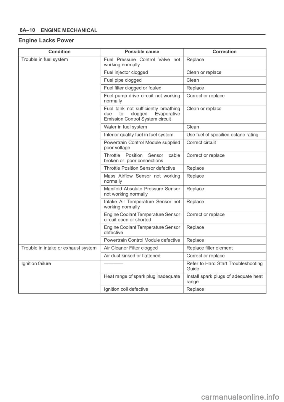
Engine Lacks Power
ConditionPossible causeCorrection
Trouble in fuel systemFuel Pressure Control Valve not
working normallyReplace
Fuel injector cloggedClean or replace
Fuel pipe cloggedClean
Fuel filter clogged or fouledReplace
Fuel pump drive circuit not working
normallyCorrect or replace
Fuel tank not sufficiently breathing
due to clogged Evaporative
Emission Control System circuitClean or replace
Water in fuel systemClean
Inferior quality fuel in fuel systemUse fuel of specified octane rating
Powertrain Control Module supplied
poor voltageCorrect circuit
Throttle Position Sensor cable
broken or poor connectionsCorrect or replace
Throttle Position Sensor defectiveReplace
Mass Airflow Sensor not working
normallyReplace
Manifold Absolute Pressure Sensor
not working normallyReplace
Intake Air Temperature Sensor not
working normallyReplace
Engine Coolant Temperature Sensor
circuit open or shortedCorrect or replace
Engine Coolant Temperature Sensor
defectiveReplace
Powertrain Control Module defectiveReplace
Trouble in intake or exhaust systemAir Cleaner Filter cloggedReplace filter element
Air duct kinked or flattenedCorrect or replace
Ignition failure————Refer to Hard Start Troubleshooting
Guide
Heat range of spark plug inadequateInstall spark plugs of adequate heat
range
Ignition coil defectiveReplace
Page 969 of 6000
6A–13
ENGINE MECHANICAL
Condition CorrectionPossible cause
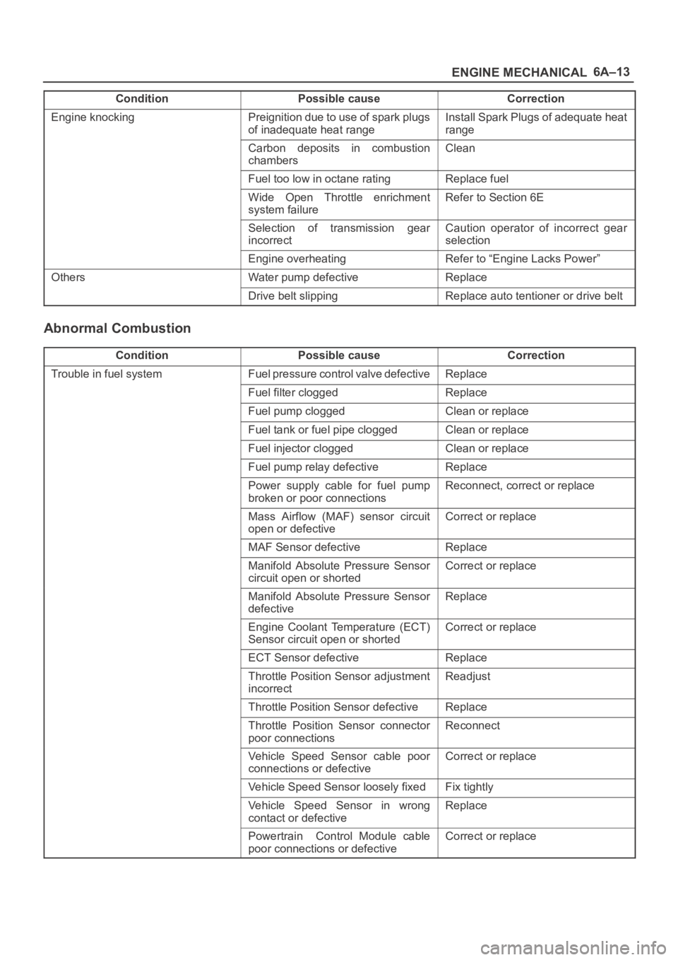
Engine knockingPreignition due to use of spark plugs
of inadequate heat rangeInstall Spark Plugs of adequate heat
range
Carbon deposits in combustion
chambersClean
Fuel too low in octane ratingReplace fuel
Wide Open Throttle enrichment
system failureRefer to Section 6E
Selection of transmission gear
incorrectCaution operator of incorrect gear
selection
Engine overheatingRefer to “Engine Lacks Power”
OthersWater pump defectiveReplace
Drive belt slippingReplace auto tentioner or drive belt
Abnormal Combustion
ConditionPossible causeCorrection
Trouble in fuel systemFuel pressure control valve defectiveReplace
Fuel filter cloggedReplace
Fuel pump cloggedClean or replace
Fuel tank or fuel pipe cloggedClean or replace
Fuel injector cloggedClean or replace
Fuel pump relay defectiveReplace
Power supply cable for fuel pump
broken or poor connectionsReconnect, correct or replace
Mass Airflow (MAF) sensor circuit
open or defectiveCorrect or replace
MAF Sensor defectiveReplace
Manifold Absolute Pressure Sensor
circuit open or shortedCorrect or replace
Manifold Absolute Pressure Sensor
defectiveReplace
Engine Coolant Temperature (ECT)
Sensor circuit open or shortedCorrect or replace
ECT Sensor defectiveReplace
Throttle Position Sensor adjustment
incorrectReadjust
Throttle Position Sensor defectiveReplace
Throttle Position Sensor connector
poor connectionsReconnect
Vehicle Speed Sensor cable poor
connections or defectiveCorrect or replace
Vehicle Speed Sensor loosely fixedFix tightly
Vehicle Speed Sensor in wrong
contact or defectiveReplace
Powertrain Control Module cable
poor connections or defectiveCorrect or replace
Page 1155 of 6000
6E–38
ENGINE DRIVEABILITY AND EMISSIONS
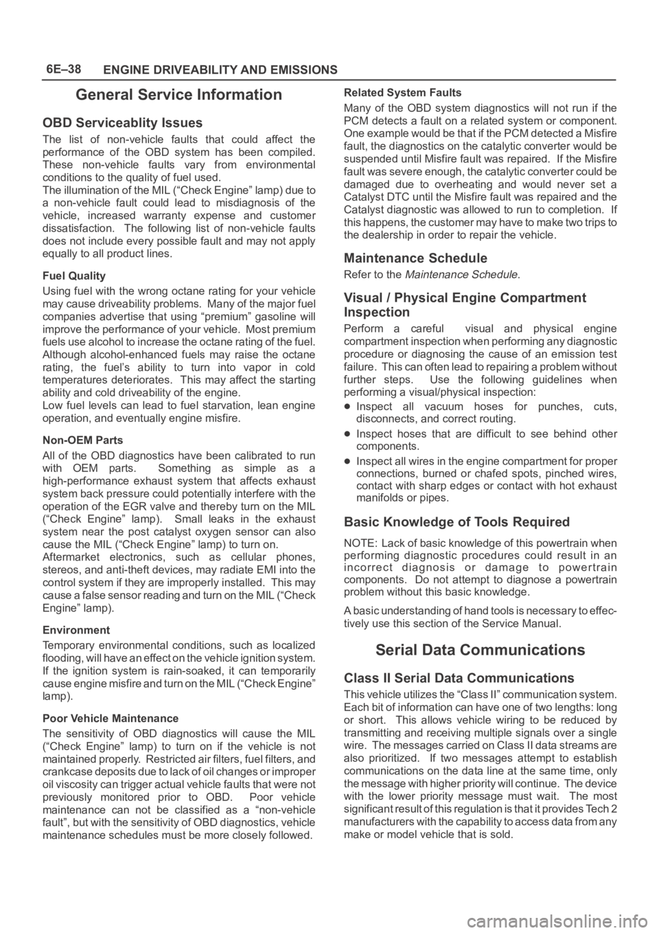
General Service Information
OBD Serviceablity Issues
The list of non-vehicle faults that could affect the
performance of the OBD system has been compiled.
These non-vehicle faults vary from environmental
conditions to the quality of fuel used.
The illumination of the MIL (“Check Engine” lamp) due to
a non-vehicle fault could lead to misdiagnosis of the
vehicle, increased warranty expense and customer
dissatisfaction. The following list of non-vehicle faults
does not include every possible fault and may not apply
equally to all product lines.
Fuel Quality
Using fuel with the wrong octane rating for your vehicle
may cause driveability problems. Many of the major fuel
companies advertise that using “premium” gasoline will
improve the performance of your vehicle. Most premium
fuels use alcohol to increase the octane rating of the fuel.
Although alcohol-enhanced fuels may raise the octane
rating, the fuel’s ability to turn into vapor in cold
temperatures deteriorates. This may affect the starting
ability and cold driveability of the engine.
Low fuel levels can lead to fuel starvation, lean engine
operation, and eventually engine misfire.
Non-OEM Parts
All of the OBD diagnostics have been calibrated to run
with OEM parts. Something as simple as a
high-performance exhaust system that affects exhaust
system back pressure could potentially interfere with the
operation of the EGR valve and thereby turn on the MIL
(“Check Engine” lamp). Small leaks in the exhaust
system near the post catalyst oxygen sensor can also
cause the MIL (“Check Engine” lamp) to turn on.
Aftermarket electronics, such as cellular phones,
stereos, and anti-theft devices, may radiate EMI into the
control system if they are improperly installed. This may
cause a false sensor reading and turn on the MIL (“Check
Engine” lamp).
Environment
Temporary environmental conditions, such as localized
flooding, will have an effect on the vehicle ignition system.
If the ignition system is rain-soaked, it can temporarily
cause engine misfire and turn on the MIL (“Check Engine”
lamp).
Poor Vehicle Maintenance
The sensitivity of OBD diagnostics will cause the MIL
(“Check Engine” lamp) to turn on if the vehicle is not
maintained properly. Restricted air filters, fuel filters, and
crankcase deposits due to lack of oil changes or improper
oil viscosity can trigger actual vehicle faults that were not
previously monitored prior to OBD. Poor vehicle
maintenance can not be classified as a “non-vehicle
fault”, but with the sensitivity of OBD diagnostics, vehicle
maintenance schedules must be more closely followed.Related System Faults
Many of the OBD system diagnostics will not run if the
PCM detects a fault on a related system or component.
One example would be that if the PCM detected a Misfire
fault, the diagnostics on the catalytic converter would be
suspended until Misfire fault was repaired. If the Misfire
fault was severe enough, the catalytic converter could be
damaged due to overheating and would never set a
Catalyst DTC until the Misfire fault was repaired and the
Catalyst diagnostic was allowed to run to completion. If
this happens, the customer may have to make two trips to
the dealership in order to repair the vehicle.
Maintenance Schedule
Refer to the Maintenance Schedule.
Visual / Physical Engine Compartment
Inspection
Perform a careful visual and physical engine
compartment inspection when performing any diagnostic
procedure or diagnosing the cause of an emission test
failure. This can often lead to repairing a problem without
further steps. Use the following guidelines when
performing a visual/physical inspection:
Inspect all vacuum hoses for punches, cuts,
disconnects, and correct routing.
Inspect hoses that are difficult to see behind other
components.
Inspect all wires in the engine compartment for proper
connections, burned or chafed spots, pinched wires,
contact with sharp edges or contact with hot exhaust
manifolds or pipes.
Basic Knowledge of Tools Required
NOTE: Lack of basic knowledge of this powertrain when
performing diagnostic procedures could result in an
incorrect diagnosis or damage to powertrain
components. Do not attempt to diagnose a powertrain
problem without this basic knowledge.
A basic understanding of hand tools is necessary to effec-
tively use this section of the Service Manual.
Serial Data Communications
Class II Serial Data Communications
This vehicle utilizes the “Class II” communication system.
Each bit of information can have one of two lengths: long
or short. This allows vehicle wiring to be reduced by
transmitting and receiving multiple signals over a single
wire. The messages carried on Class II data streams are
also prioritized. If two messages attempt to establish
communications on the data line at the same time, only
the message with higher priority will continue. The device
with the lower priority message must wait. The most
significant result of this regulation is that it provides Tech 2
manufacturers with the capability to access data from any
make or model vehicle that is sold.
Page 1387 of 6000
6E–270
ENGINE DRIVEABILITY AND EMISSIONS
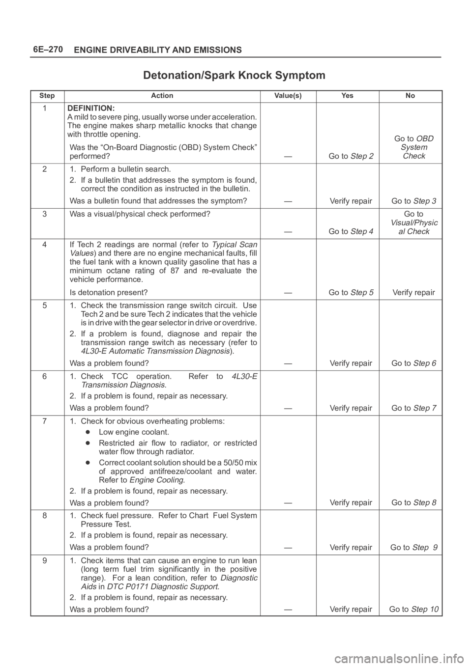
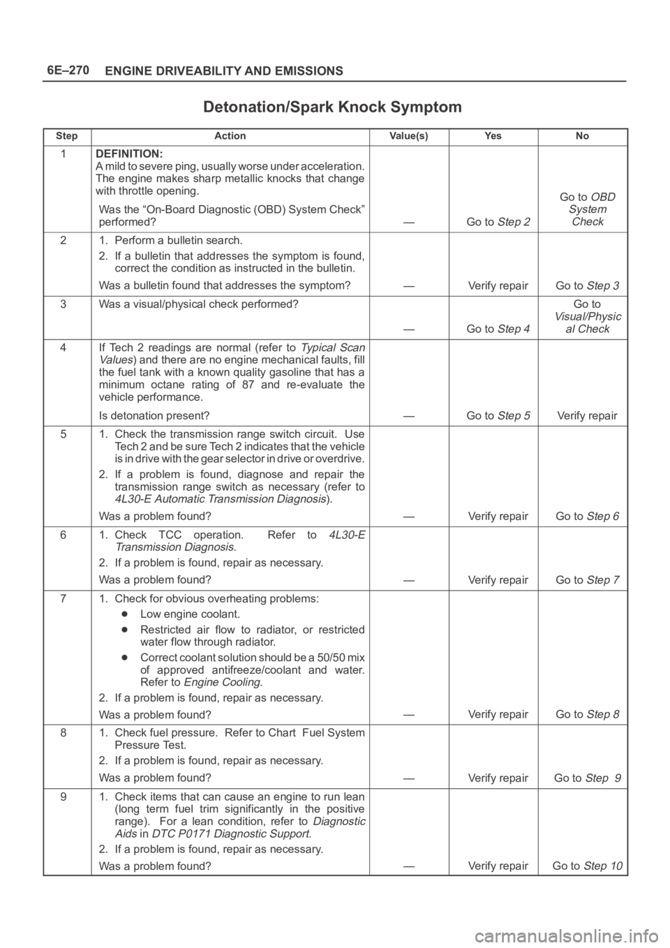
Detonation/Spark Knock Symptom
StepActionVa l u e ( s )Ye sNo
1DEFINITION:
A mild to severe ping, usually worse under acceleration.
The engine makes sharp metallic knocks that change
with throttle opening.
Was the “On-Board Diagnostic (OBD) System Check”
performed?
—Go to Step 2
Go to OBD
System
Check
21. Perform a bulletin search.
2. If a bulletin that addresses the symptom is found,
correct the condition as instructed in the bulletin.
Was a bulletin found that addresses the symptom?
—Verify repairGo to Step 3
3Was a visual/physical check performed?
—Go to Step 4
Go to
Visual/Physic
al Check
4If Tech 2 readings are normal (refer to Ty p i c a l S c a n
Va lu es
) and there are no engine mechanical faults, fill
the fuel tank with a known quality gasoline that has a
minimum octane rating of 87 and re-evaluate the
vehicle performance.
Is detonation present?
—Go to Step 5Verify repair
51. Check the transmission range switch circuit. Use
Tech 2 and be sure Tech 2 indicates that the vehicle
is in drive with the gear selector in drive or overdrive.
2. If a problem is found, diagnose and repair the
transmission range switch as necessary (refer to
4L30-E Automatic Transmission Diagnosis).
Was a problem found?
—Verify repairGo to Step 6
61. Check TCC operation. Refer to 4L30-E
Transmission Diagnosis
.
2. If a problem is found, repair as necessary.
Was a problem found?
—Verify repairGo to Step 7
71. Check for obvious overheating problems:
Low engine coolant.
Restricted air flow to radiator, or restricted
water flow through radiator.
Correct coolant solution should be a 50/50 mix
of approved antifreeze/coolant and water.
Refer to
Engine Cooling.
2. If a problem is found, repair as necessary.
Was a problem found?
—Verify repairGo to Step 8
81. Check fuel pressure. Refer to Chart Fuel System
Pressure Test.
2. If a problem is found, repair as necessary.
Was a problem found?
—Verify repairGo to Step 9
91. Check items that can cause an engine to run lean
(long term fuel trim significantly in the positive
range). For a lean condition, refer to
Diagnostic
Aids
in DTC P0171 Diagnostic Support.
2. If a problem is found, repair as necessary.
Was a problem found?
—Verify repairGo to Step 10
Page 1454 of 6000
6E–337 ENGINE DRIVEABILITY AND EMISSIONS
0018
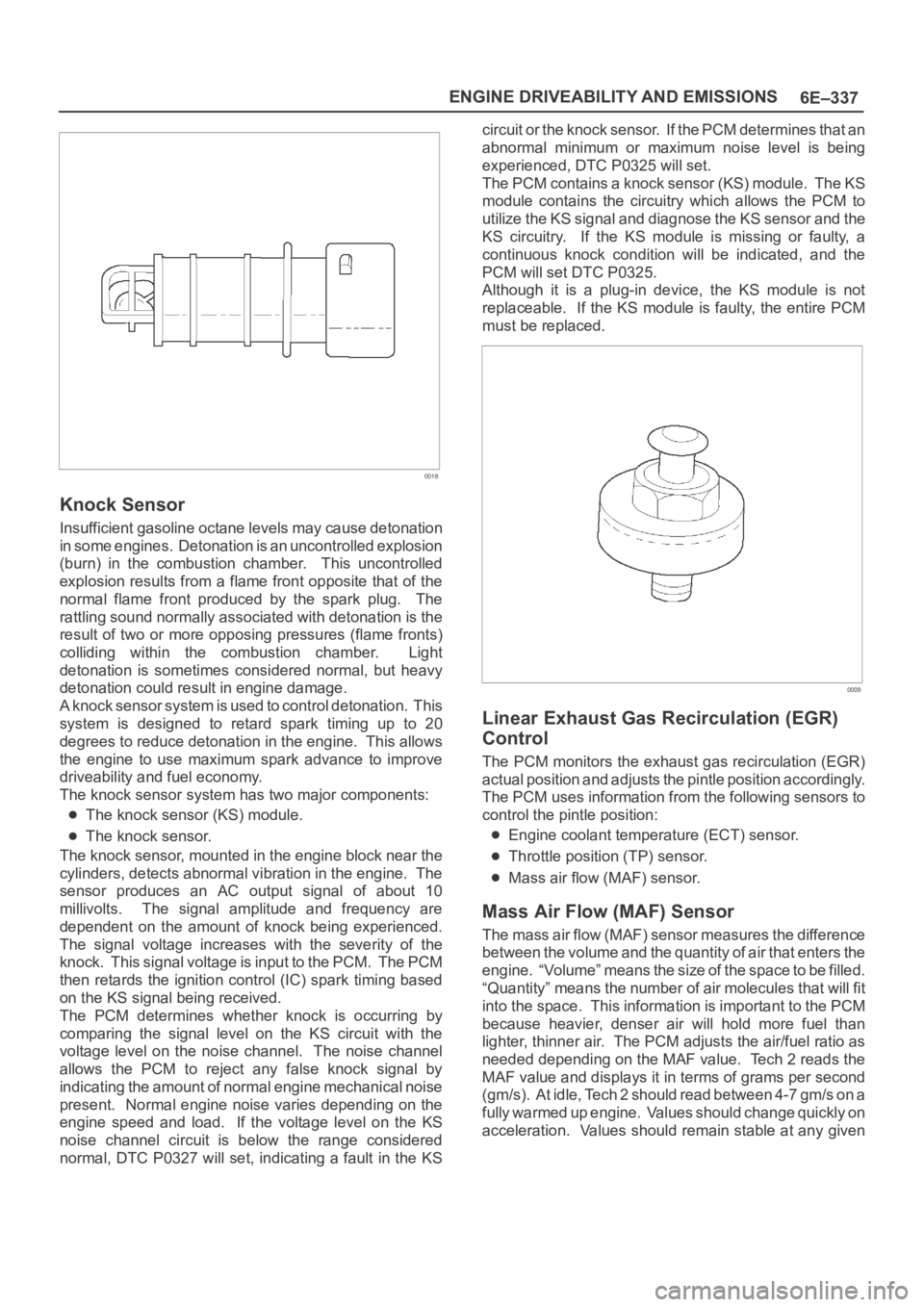
Knock Sensor
Insufficient gasoline octane levels may cause detonation
in some engines. Detonation is an uncontrolled explosion
(burn) in the combustion chamber. This uncontrolled
explosion results from a flame front opposite that of the
normal flame front produced by the spark plug. The
rattling sound normally associated with detonation is the
result of two or more opposing pressures (flame fronts)
colliding within the combustion chamber. Light
detonation is sometimes considered normal, but heavy
detonation could result in engine damage.
A knock sensor system is used to control detonation. This
system is designed to retard spark timing up to 20
degrees to reduce detonation in the engine. This allows
the engine to use maximum spark advance to improve
driveability and fuel economy.
The knock sensor system has two major components:
The knock sensor (KS) module.
The knock sensor.
The knock sensor, mounted in the engine block near the
cylinders, detects abnormal vibration in the engine. The
sensor produces an AC output signal of about 10
millivolts. The signal amplitude and frequency are
dependent on the amount of knock being experienced.
The signal voltage increases with the severity of the
knock. This signal voltage is input to the PCM. The PCM
then retards the ignition control (IC) spark timing based
on the KS signal being received.
The PCM determines whether knock is occurring by
comparing the signal level on the KS circuit with the
voltage level on the noise channel. The noise channel
allows the PCM to reject any false knock signal by
indicating the amount of normal engine mechanical noise
present. Normal engine noise varies depending on the
engine speed and load. If the voltage level on the KS
noise channel circuit is below the range considered
normal, DTC P0327 will set, indicating a fault in the KScircuit or the knock sensor. If the PCM determines that an
abnormal minimum or maximum noise level is being
experienced, DTC P0325 will set.
The PCM contains a knock sensor (KS) module. The KS
module contains the circuitry which allows the PCM to
utilize the KS signal and diagnose the KS sensor and the
KS circuitry. If the KS module is missing or faulty, a
continuous knock condition will be indicated, and the
PCM will set DTC P0325.
Although it is a plug-in device, the KS module is not
replaceable. If the KS module is faulty, the entire PCM
must be replaced.
0009
Linear Exhaust Gas Recirculation (EGR)
Control
The PCM monitors the exhaust gas recirculation (EGR)
actual position and adjusts the pintle position accordingly.
The PCM uses information from the following sensors to
control the pintle position:
Engine coolant temperature (ECT) sensor.
Throttle position (TP) sensor.
Mass air flow (MAF) sensor.
Mass Air Flow (MAF) Sensor
The mass air flow (MAF) sensor measures the difference
between the volume and the quantity of air that enters the
engine. “Volume” means the size of the space to be filled.
“Quantity” means the number of air molecules that will fit
into the space. This information is important to the PCM
because heavier, denser air will hold more fuel than
lighter, thinner air. The PCM adjusts the air/fuel ratio as
needed depending on the MAF value. Tech 2 reads the
MAF value and displays it in terms of grams per second
(gm/s). At idle, Tech 2 should read between 4-7 gm/s on a
fully warmed up engine. Values should change quickly on
acceleration. Values should remain stable at any given
Page 4506 of 6000

6A–10
ENGINE MECHANICAL
Engine Lacks Power
ConditionPossible causeCorrection
Trouble in fuel systemFuel Pressure Control Valve not
working normallyReplace
Fuel injector cloggedClean or replace
Fuel pipe cloggedClean
Fuel filter clogged or fouledReplace
Fuel pump drive circuit not working
normallyCorrect or replace
Fuel tank not sufficiently breathing
due to clogged Evaporative
Emission Control System circuitClean or replace
Water in fuel systemClean
Inferior quality fuel in fuel systemUse fuel of specified octane rating
Powertrain Control Module supplied
poor voltageCorrect circuit
Throttle Position Sensor cable
broken or poor connectionsCorrect or replace
Throttle Position Sensor defectiveReplace
Mass Airflow Sensor not working
normallyReplace
Manifold Absolute Pressure Sensor
not working normallyReplace
Intake Air Temperature Sensor not
working normallyReplace
Engine Coolant Temperature Sensor
circuit open or shortedCorrect or replace
Engine Coolant Temperature Sensor
defectiveReplace
Powertrain Control Module defectiveReplace
Trouble in intake or exhaust systemAir Cleaner Filter cloggedReplace filter element
Air duct kinked or flattenedCorrect or replace
Ignition failure————Refer to Hard Start Troubleshooting
Guide
Heat range of spark plug inadequateInstall spark plugs of adequate heat
range
Ignition coil defectiveReplace
Page 4509 of 6000

6A–13
ENGINE MECHANICAL
Condition CorrectionPossible cause
Engine knockingPreignition due to use of spark plugs
of inadequate heat rangeInstall Spark Plugs of adequate heat
range
Carbon deposits in combustion
chambersClean
Fuel too low in octane ratingReplace fuel
Wide Open Throttle enrichment
system failureRefer to Section 6E
Selection of transmission gear
incorrectCaution operator of incorrect gear
selection
Engine overheatingRefer to “Engine Lacks Power”
OthersWater pump defectiveReplace
Drive belt slippingReplace auto tentioner or drive belt
Abnormal Combustion
ConditionPossible causeCorrection
Trouble in fuel systemFuel pressure control valve defectiveReplace
Fuel filter cloggedReplace
Fuel pump cloggedClean or replace
Fuel tank or fuel pipe cloggedClean or replace
Fuel injector cloggedClean or replace
Fuel pump relay defectiveReplace
Power supply cable for fuel pump
broken or poor connectionsReconnect, correct or replace
Mass Airflow (MAF) sensor circuit
open or defectiveCorrect or replace
MAF Sensor defectiveReplace
Manifold Absolute Pressure Sensor
circuit open or shortedCorrect or replace
Manifold Absolute Pressure Sensor
defectiveReplace
Engine Coolant Temperature (ECT)
Sensor circuit open or shortedCorrect or replace
ECT Sensor defectiveReplace
Throttle Position Sensor adjustment
incorrectReadjust
Throttle Position Sensor defectiveReplace
Throttle Position Sensor connector
poor connectionsReconnect
Vehicle Speed Sensor cable poor
connections or defectiveCorrect or replace
Vehicle Speed Sensor loosely fixedFix tightly
Vehicle Speed Sensor in wrong
contact or defectiveReplace
Powertrain Control Module cable
poor connections or defectiveCorrect or replace
Page 4695 of 6000
6E–38
ENGINE DRIVEABILITY AND EMISSIONS
General Service Information
OBD Serviceablity Issues
The list of non-vehicle faults that could affect the
performance of the OBD system has been compiled.
These non-vehicle faults vary from environmental
conditions to the quality of fuel used.
The illumination of the MIL (“Check Engine” lamp) due to
a non-vehicle fault could lead to misdiagnosis of the
vehicle, increased warranty expense and customer
dissatisfaction. The following list of non-vehicle faults
does not include every possible fault and may not apply
equally to all product lines.
Fuel Quality
Using fuel with the wrong octane rating for your vehicle
may cause driveability problems. Many of the major fuel
companies advertise that using “premium” gasoline will
improve the performance of your vehicle. Most premium
fuels use alcohol to increase the octane rating of the fuel.
Although alcohol-enhanced fuels may raise the octane
rating, the fuel’s ability to turn into vapor in cold
temperatures deteriorates. This may affect the starting
ability and cold driveability of the engine.
Low fuel levels can lead to fuel starvation, lean engine
operation, and eventually engine misfire.
Non-OEM Parts
All of the OBD diagnostics have been calibrated to run
with OEM parts. Something as simple as a
high-performance exhaust system that affects exhaust
system back pressure could potentially interfere with the
operation of the EGR valve and thereby turn on the MIL
(“Check Engine” lamp). Small leaks in the exhaust
system near the post catalyst oxygen sensor can also
cause the MIL (“Check Engine” lamp) to turn on.
Aftermarket electronics, such as cellular phones,
stereos, and anti-theft devices, may radiate EMI into the
control system if they are improperly installed. This may
cause a false sensor reading and turn on the MIL (“Check
Engine” lamp).
Environment
Temporary environmental conditions, such as localized
flooding, will have an effect on the vehicle ignition system.
If the ignition system is rain-soaked, it can temporarily
cause engine misfire and turn on the MIL (“Check Engine”
lamp).
Poor Vehicle Maintenance
The sensitivity of OBD diagnostics will cause the MIL
(“Check Engine” lamp) to turn on if the vehicle is not
maintained properly. Restricted air filters, fuel filters, and
crankcase deposits due to lack of oil changes or improper
oil viscosity can trigger actual vehicle faults that were not
previously monitored prior to OBD. Poor vehicle
maintenance can not be classified as a “non-vehicle
fault”, but with the sensitivity of OBD diagnostics, vehicle
maintenance schedules must be more closely followed.Related System Faults
Many of the OBD system diagnostics will not run if the
PCM detects a fault on a related system or component.
One example would be that if the PCM detected a Misfire
fault, the diagnostics on the catalytic converter would be
suspended until Misfire fault was repaired. If the Misfire
fault was severe enough, the catalytic converter could be
damaged due to overheating and would never set a
Catalyst DTC until the Misfire fault was repaired and the
Catalyst diagnostic was allowed to run to completion. If
this happens, the customer may have to make two trips to
the dealership in order to repair the vehicle.
Maintenance Schedule
Refer to the Maintenance Schedule.
Visual / Physical Engine Compartment
Inspection
Perform a careful visual and physical engine
compartment inspection when performing any diagnostic
procedure or diagnosing the cause of an emission test
failure. This can often lead to repairing a problem without
further steps. Use the following guidelines when
performing a visual/physical inspection:
Inspect all vacuum hoses for punches, cuts,
disconnects, and correct routing.
Inspect hoses that are difficult to see behind other
components.
Inspect all wires in the engine compartment for proper
connections, burned or chafed spots, pinched wires,
contact with sharp edges or contact with hot exhaust
manifolds or pipes.
Basic Knowledge of Tools Required
NOTE: Lack of basic knowledge of this powertrain when
performing diagnostic procedures could result in an
incorrect diagnosis or damage to powertrain
components. Do not attempt to diagnose a powertrain
problem without this basic knowledge.
A basic understanding of hand tools is necessary to effec-
tively use this section of the Service Manual.
Serial Data Communications
Class II Serial Data Communications
This vehicle utilizes the “Class II” communication system.
Each bit of information can have one of two lengths: long
or short. This allows vehicle wiring to be reduced by
transmitting and receiving multiple signals over a single
wire. The messages carried on Class II data streams are
also prioritized. If two messages attempt to establish
communications on the data line at the same time, only
the message with higher priority will continue. The device
with the lower priority message must wait. The most
significant result of this regulation is that it provides Tech 2
manufacturers with the capability to access data from any
make or model vehicle that is sold.
Page 4927 of 6000
6E–270
ENGINE DRIVEABILITY AND EMISSIONS
Detonation/Spark Knock Symptom
StepActionVa l u e ( s )Ye sNo
1DEFINITION:
A mild to severe ping, usually worse under acceleration.
The engine makes sharp metallic knocks that change
with throttle opening.
Was the “On-Board Diagnostic (OBD) System Check”
performed?
—Go to Step 2
Go to OBD
System
Check
21. Perform a bulletin search.
2. If a bulletin that addresses the symptom is found,
correct the condition as instructed in the bulletin.
Was a bulletin found that addresses the symptom?
—Verify repairGo to Step 3
3Was a visual/physical check performed?
—Go to Step 4
Go to
Visual/Physic
al Check
4If Tech 2 readings are normal (refer to Ty p i c a l S c a n
Va lu es
) and there are no engine mechanical faults, fill
the fuel tank with a known quality gasoline that has a
minimum octane rating of 87 and re-evaluate the
vehicle performance.
Is detonation present?
—Go to Step 5Verify repair
51. Check the transmission range switch circuit. Use
Tech 2 and be sure Tech 2 indicates that the vehicle
is in drive with the gear selector in drive or overdrive.
2. If a problem is found, diagnose and repair the
transmission range switch as necessary (refer to
4L30-E Automatic Transmission Diagnosis).
Was a problem found?
—Verify repairGo to Step 6
61. Check TCC operation. Refer to 4L30-E
Transmission Diagnosis
.
2. If a problem is found, repair as necessary.
Was a problem found?
—Verify repairGo to Step 7
71. Check for obvious overheating problems:
Low engine coolant.
Restricted air flow to radiator, or restricted
water flow through radiator.
Correct coolant solution should be a 50/50 mix
of approved antifreeze/coolant and water.
Refer to
Engine Cooling.
2. If a problem is found, repair as necessary.
Was a problem found?
—Verify repairGo to Step 8
81. Check fuel pressure. Refer to Chart Fuel System
Pressure Test.
2. If a problem is found, repair as necessary.
Was a problem found?
—Verify repairGo to Step 9
91. Check items that can cause an engine to run lean
(long term fuel trim significantly in the positive
range). For a lean condition, refer to
Diagnostic
Aids
in DTC P0171 Diagnostic Support.
2. If a problem is found, repair as necessary.
Was a problem found?
—Verify repairGo to Step 10
Page 4994 of 6000

6E–337 ENGINE DRIVEABILITY AND EMISSIONS
0018
Knock Sensor
Insufficient gasoline octane levels may cause detonation
in some engines. Detonation is an uncontrolled explosion
(burn) in the combustion chamber. This uncontrolled
explosion results from a flame front opposite that of the
normal flame front produced by the spark plug. The
rattling sound normally associated with detonation is the
result of two or more opposing pressures (flame fronts)
colliding within the combustion chamber. Light
detonation is sometimes considered normal, but heavy
detonation could result in engine damage.
A knock sensor system is used to control detonation. This
system is designed to retard spark timing up to 20
degrees to reduce detonation in the engine. This allows
the engine to use maximum spark advance to improve
driveability and fuel economy.
The knock sensor system has two major components:
The knock sensor (KS) module.
The knock sensor.
The knock sensor, mounted in the engine block near the
cylinders, detects abnormal vibration in the engine. The
sensor produces an AC output signal of about 10
millivolts. The signal amplitude and frequency are
dependent on the amount of knock being experienced.
The signal voltage increases with the severity of the
knock. This signal voltage is input to the PCM. The PCM
then retards the ignition control (IC) spark timing based
on the KS signal being received.
The PCM determines whether knock is occurring by
comparing the signal level on the KS circuit with the
voltage level on the noise channel. The noise channel
allows the PCM to reject any false knock signal by
indicating the amount of normal engine mechanical noise
present. Normal engine noise varies depending on the
engine speed and load. If the voltage level on the KS
noise channel circuit is below the range considered
normal, DTC P0327 will set, indicating a fault in the KScircuit or the knock sensor. If the PCM determines that an
abnormal minimum or maximum noise level is being
experienced, DTC P0325 will set.
The PCM contains a knock sensor (KS) module. The KS
module contains the circuitry which allows the PCM to
utilize the KS signal and diagnose the KS sensor and the
KS circuitry. If the KS module is missing or faulty, a
continuous knock condition will be indicated, and the
PCM will set DTC P0325.
Although it is a plug-in device, the KS module is not
replaceable. If the KS module is faulty, the entire PCM
must be replaced.
0009
Linear Exhaust Gas Recirculation (EGR)
Control
The PCM monitors the exhaust gas recirculation (EGR)
actual position and adjusts the pintle position accordingly.
The PCM uses information from the following sensors to
control the pintle position:
Engine coolant temperature (ECT) sensor.
Throttle position (TP) sensor.
Mass air flow (MAF) sensor.
Mass Air Flow (MAF) Sensor
The mass air flow (MAF) sensor measures the difference
between the volume and the quantity of air that enters the
engine. “Volume” means the size of the space to be filled.
“Quantity” means the number of air molecules that will fit
into the space. This information is important to the PCM
because heavier, denser air will hold more fuel than
lighter, thinner air. The PCM adjusts the air/fuel ratio as
needed depending on the MAF value. Tech 2 reads the
MAF value and displays it in terms of grams per second
(gm/s). At idle, Tech 2 should read between 4-7 gm/s on a
fully warmed up engine. Values should change quickly on
acceleration. Values should remain stable at any given