oil OPEL FRONTERA 1998 Workshop Manual
[x] Cancel search | Manufacturer: OPEL, Model Year: 1998, Model line: FRONTERA, Model: OPEL FRONTERA 1998Pages: 6000, PDF Size: 97 MB
Page 2238 of 6000

7A–84
AUTOMATIC TRANSMISSION (4L30–E)
4L30–E Parts List
Case And Associated Parts
241RW014
Legend
(1) Torque Converter
(2) Screw, Seal Ring Assembly
(3) Seal Ring Assembly, Converter Housing
(4) Screw, Converter Housing/Main Case
(5) Screw, Converter Housing/Oil Pump
(6) Housing, Converter
(7) Plug, Converter Housing
(8) Seal, O–Ring
(9) Wear Plate, Oil Pump Body
(10) Pump Assembly, Oil
(11) Gasket
(12) Washer, Thrust Selective
(13) Ring, Snap
(14) Cover, 3–4 Accumulator Piston
(15) Seal, O–Ring, 3–4 Accumulator
(16) Spring, 3–4 Accumulator Piston(17) Pin, 3–4 Accumulator Piston
(18) Piston, 3–4 Accumulator
(19) Ring, 3–4, Accumulator Piston
(20) Case, Adapter
(22) Connector, Electrical/Adapter Case
(23) Screw, Pan
(27) Restrictor, Oil
(28) Gasket, Transfer Plate/Adapter
(29) Plate, Transfer Adapter/Center Support
(30) Support Assembly, Center
(31) Screw, Center Support
(32) Ring, Oil Seal
(33) Seal, O–Ring Main Case
(34) Fitting, Cooler
(35) Fitting Assembly, Cooler
(36) Case, Main
(37) Breather, Pipe
Page 2239 of 6000

7A–85 AUTOMATIC TRANSMISSION (4L30–E)
(38) Seal, O–Ring
(39) Reservoir
(42) Gasket, Extension Case
(43) Extension Assembly
(44) Seal, O–Ring/Speed Sensor
(45) Sensor Assembly, Speed
(46) Screw, Speed Sensor
(50) Seal, Extension Assembly
(52) Screw, Extension/Main Case
(53) Spring, Parking Pawl Lock
(54) Pawl, Parking Lock
(55) Connector, Electrical/Main Case
(56) Actuator Assembly, Parking Lock
(57) Nut, Parking Lock Lever
(58) Link, Manual Valve
(59) Pin, Spring
(60) Lever, Parking Lock and Range Selector
(61) Shaft, Selector
(62) Seal, Selector Shaft
(63) Mode Switch Assembly
(64) Screw and Conical Washer Assembly
(65) Shield, Mode Switch
(67) Pan, Bottom/Adapter Case
(68) Gasket, Bottom Pan/Adapter Case
(69) Harness Assembly, Adapter Case
(70) Screw, Valve Body
(71) Valve Body Assembly, Adapter Case
(72) Gasket, Adapter Valve Body
(73) Plate, Adapter Valve Body/Transfer
(74) Pan, Bottom/Main Case(75) Gasket, Bottom Pan/Main Case
(76) Gasket, Oil Drain or Overfill Screw
(77) Screw, Oil Drain or Overfill
(78) Magnet, Chip Collector
(79) Filter Oil
(80) Harness Assembly, Main Case
(82) Roller and Spring Assembly, Manual Detent
(84) Valve Body Assembly, Main Case
(85) Ball, Check
(86) Gasket, Main V.B./Transfer Plate
(87) Plate, Main V.B./Transfer
(88) Gasket, Transfer/Main Case
(89) Screw, Transfer Plate on V.B.
(90) Screw, Servo Cover
(91) Cover, Servo Piston
(92) Gasket, Cover/Servo Piston
(93) Ring, Retaining Servo Piston
(94) Clip, Servo Piston
(95) Nut, Servo Screw
(96) Screw, Servo Piston
(97) Piston, Servo
(98) Seal, Ring/Servo Piston
(99) Spring, Cushion/Servo Piston
(100) Seat, Cushion Spring
(101) Sleeve, Servo Piston Adjust
(102) Rod, Apply/Servo Piston
(103) Spring, Return/Servo Piston
(104) Gasket, Adapter Case/Transfer Plate
(105) Powertrain Control Module
(106) Servo Piston Assembly
Page 2240 of 6000

7A–86
AUTOMATIC TRANSMISSION (4L30–E)
Pump Assembly
241RS019
Legend
(201) Gear, Oil Pump Drive
(202) Gear, Oil Pump Driven
(203) Pin, Boost Valve Sleeve
(204) Sleeve, Boost Valve
(205) Valve, Boost
(206) Seat, Spring/Pressure Regulator Valve
(207) Spring, Pressure Regulator Valve
(208) Valve, Pressure Regulator(209) Pump Assembly, Oil
(210) Valve, Converter Clutch Control
(211) Spring, Converter Clutch Control Valve
(212) Plug, Converter Clutch Control Valve
(213) Pin, Spring
(214) Piston, Throttle Signal Accumulator
(215) Spring, Throttle Signal Accumulator
(216) Seat, Spring/Throttle Signal Accumulator
(217) Ring, Snap/Throttle Signal Accumulator
Page 2243 of 6000

7A–89 AUTOMATIC TRANSMISSION (4L30–E)
Overdrive Internal Components
252RW003
Legend
(501) Retainer, 4th Clutch
(502) Plate, 4th Clutch (Steel)
(503) Plate Assembly, 4th Clutch (Lined)
(504) Retainer And Ball Assembly, Check Valve
(505) Seal, O–Ring/Turbine Shaft
(506) Shaft, Turbine
(508) Ring, Oil Seal/Turbine Shaft
(510) Housing, Overrun Clutch
(513) Piston, Overrun Clutch
(514) Spring, Overrun Clutch Release
(515) Retainer, Release Spring/Overrun Clutch
(516) Roller Assembly, Overdrive Clutch
(517) Cam, Overdrive Roller Clutch
(518) Ring, Snap/Overrun Clutch Hub
(519) Gear, Overdrive Sun(520) Plate, Waved/Overrun Clutch
(521) Plate, Overrun Clutch (Steel)
(522) Plate Assembly, Overrun Clutch (Lined)
(523) Plate, Backing/Overrun Clutch
(524) Ring, Snap/Overrun Clutch Housing
(525) Carrier Assembly, Overdrive Complete
(526) Ring, Snap/Turbine Shaft/Carrier
(527) Bearing Assembly, Thrust
(528) Gear, Overdrive Internal
(529) Washer, Thrust/Internal Gear/Support
(530) Ring, Snap/Adapter/4th Clutch Spring
(531) Retainer and spring assembly, 4th clutch
(532) Piston, 4th Clutch
(533) Seal, 4th Clutch Piston (Inner)
(534) Seal, 4th Clutch Piston (outer)
Page 2251 of 6000

7A1–6
TRANSMISSION CONTROL SYSTEM (4L30–E)
Shift Control
The transmission gear is shifted according to the shift
pattern selected by the driver. In shifting gears, the gear
ratio is controlled by the ON/ OFF signal using the shift
solenoid A and the shift solenoid B.
Band Apply Control
The band apply is controlled when in the 3–2 downshift
(engine overrun prevention) and the garage shift (shock
control).
The band apply solenoid is controlled by the signal from
the Pulse Width Modulation (PWM) to regulate the flow of
the oil.
Torque Converter Clutch Control
The clutch ON/OFF is controlled by moving the converter
clutch valve through shifting Torque Converter Clutch
(TCC) solenoid using the ON/OFF signal.
Line Pressure Control
The throttle signal allows the current signal to be sent to
the force motor. After receiving the current signal, the
force motor activates the pressure regulator valve to
regulate the line pressure.
On–Board Diagnostic System
Several malfunction displays can be stored in the
Powertrain Control Module (PCM) memory, and read out
of it afterward.The serial data lines, which are required for the testing of
the final assembly and the coupling to other electronic
modules, can be regulated by this function.
Fail Safe Mechanism
If there is a problem in the transmission system, the PCM
will go into a “backup” mode.
The vehicle can still be driven, but the driver must use the
select lever to shift gears.
Torque Management Control
The transmission control side sends the absolute spark
advance signal to the engine control side while the
transmission is being shifted. This controls the engine
spark timing in compliance with the vehicle running
condition to reduce the shocks caused by the change of
speed.
ATF Warning Control
The oil temperature sensor detects the ATF oil
temperature to control the oil temperature warning, TCC,
and the winter mode.
ABS Control (If equipped)
When the select lever is at “L” or “R” range, a signal is sent
to the ABS controller as one of the ABS control
conditions.
Page 2254 of 6000

TRANSMISSION CONTROL SYSTEM (4L30–E)7A1–9
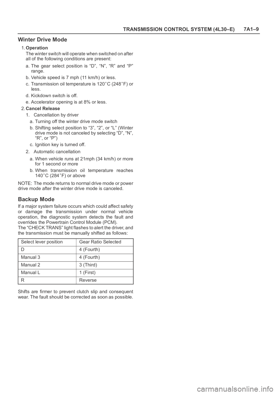
Winter Drive Mode
1.Operation
The winter switch will operate when switched on after
all of the following conditions are present:
a. The gear select position is “D”, “N”, “R” and “P”
range.
b. Vehicle speed is 7 mph (11 km/h) or less.
c. Transmission oil temperature is 120
C (248F) or
less.
d. Kickdown switch is off.
e. Accelerator opening is at 8% or less.
2.Cancel Release
1. Cancellation by driver
a. Turning off the winter drive mode switch
b. Shifting select position to “3”, “2”, or “L” (Winter
drive mode is not canceled by selecting “D”, “N”,
“R”, or “P”)
c. Ignition key is turned off.
2. Automatic cancellation
a. When vehicle runs at 21mph (34 km/h) or more
for 1 second or more
b. When transmission oil temperature reaches
140
C (284F) or above
NOTE: The mode returns to normal drive mode or power
drive mode after the winter drive mode is canceled.
Backup Mode
If a major system failure occurs which could affect safety
or damage the transmission under normal vehicle
operation, the diagnostic system detects the fault and
overrides the Powertrain Control Module (PCM).
The “CHECK TRANS” light flashes to alert the driver, and
the transmission must be manually shifted as follows:
Select lever position
Gear Ratio Selected
D4 (Fourth)
Manual 34 (Fourth)
Manual 23 (Third)
Manual L1 (First)
RReverse
Shifts are firmer to prevent clutch slip and consequent
wear. The fault should be corrected as soon as possible.
Page 2255 of 6000

7A1–10
TRANSMISSION CONTROL SYSTEM (4L30–E)
Functions of Input / Output Components
ComponentsFunction
Speed sensor
(fixed to transmission
(T/M))Senses rotation of output shaft and feeds the data to Powertrain Control Module
(PCM).
Throttle position sensor
(TPS)
(fixed to engine)Senses the extent of throttle valve opening and the speed of the throttle valve
lever motion to open the valve. Feeds the data to PCM.
I
N
Brake Switch (SW)
(fixed to brake pedal)Senses whether the driver has pressed the brake pedal or not and feeds the
information to PCM.
N-
P
U
Kickdown SW
(fixed to accelerator pedal)Senses whether the driver has pushed the accelerator pedal fully or not, and
feeds the information to PCM.
U
TMode SW (fixed to T/M)Senses the select lever position, and feeds the information to PCM.
S
I
Power drive SW
(fixed to front console)Senses whether the driver has selected the power mode, and feeds the informa-
tion to PCM.
I
G-T/M oil temp. sensorSenses the T/M oil temperature and feeds the data to PCM
N
A
L
Engine coolant tempera-
ture sensorSenses the engine coolant temperature, and feeds the data to PCM.
LEngine speed signalFeeds the signals monitoring engine speed to PCM from crank angle sensor.
Air conditioning informationSenses whether the air conditioner has been switched on or not, and feeds the
information to PCM.
Winter switch (fixed to front
console)Senses whether the driver has selected the winter mode, and feeds the informa-
tion to PCM.
Cruise controller * (Over-
drive OFF signal)Downshift takes place when Overdrive OFF signal is received from auto cruise
control unit.
S
Shift solenoid A, BSelects shift point and gear position suited to the vehicle running condition on
the basis of PCM output.
O
S
O-
L
Band apply solenoidControls oil flow suited to the vehicle running condition on the basis of PCM out-
put.
O
U
T-
P
E-
N
O
Torque Converter
Clutch solenoidControls clutch engagement/disengagement suited to the vehicle running condi-
tion on the basis of PCM output.
P
U
T
O
I
DForce motor
(Pressure regulator
valve)Adjusts the oil pump delivery pressure to line pressure suited to the vehicle run-
ning condition on the basis of PCM output.
S
I
Power drive mode lampInforms the driver whether the vehicle is in power mode or not.
I
G-Winter drive mode lampInforms the driver whether the vehicle is in winter mode or not.G
N
A
L
T/M monitor lamp
(“CHECK TRANS”)Informs the driver of failure in the system.
LATF warning lampLights when ATF oil temperature rises.
ABS signal *When the select lever is at “Reverse” or “L” range, sends a signal to the ABS
controller as one of the ABS control conditions.
* If equipped
Page 2267 of 6000

7A1–22
TRANSMISSION CONTROL SYSTEM (4L30–E)
connection or loose wiring. Terminals and grounds should
always be the prime suspect. Intermittents rarely occur
inside sophisticated electronic components such as the
PCM.
Use the DTC information to understand which wires and
sensors are involved.
When an intermittent problem is encountered, check
suspect circuits for:
1. Poor terminal to wire connection.
2. Terminals not fully seated in the connector body
(backed out).
3. Improperly formed or damaged terminals.
4. Loose, dirty, or corroded ground connections:
HINT: Any time you have an intermittent in more than
one circuit, check whether the circuits share a
common ground connection.
5. Pinched or damaged wires.
6. Electro–Magnetic Interference (EMI):
HINT: Check that all wires are properly routed away
from spark plug wires, distributor wires, coil, and
generator. Also check for improperly installed
electrical options, such as lights, 2–way radios, etc.Use the F3 SNAPSHOT mode of the Tech2 to help isolate
the cause of an intermittent fault. The snapshot mode will
record information before and after the problem occurs.
Set the snapshot to “trigger” on the suspect DTC. If you
notice the reported symptom during the test drive, trigger
the snapshot manually.
After the snapshot has been triggered, command the
Tech2 to play back the flow of data recorded from each of
the various sensors. Signs of an intermittent fault in a
sensor circuit are sudden unexplainable jump in data
values out of the normal range.
Transmission And PCM Identification
The chart below contains a list of all important information
concerning rear axle ratio, Powertrain Control Module
(PCM), and transmission identification.
VEHICLE
Rr axlePCMTRANSMISSION
Ty p eEngine
Rr axle
RatioISUZU Parts No.Calibration
CodeIsuzu Part No.Model Code
Isuzu /
Trooper3.2L V64.555
8–16254–949–0
8–16254–749–0
8–16253–989–0
G208–96018–272–3FP (4X4)
Page 2282 of 6000

TRANSMISSION CONTROL SYSTEM (4L30–E)7A1–37
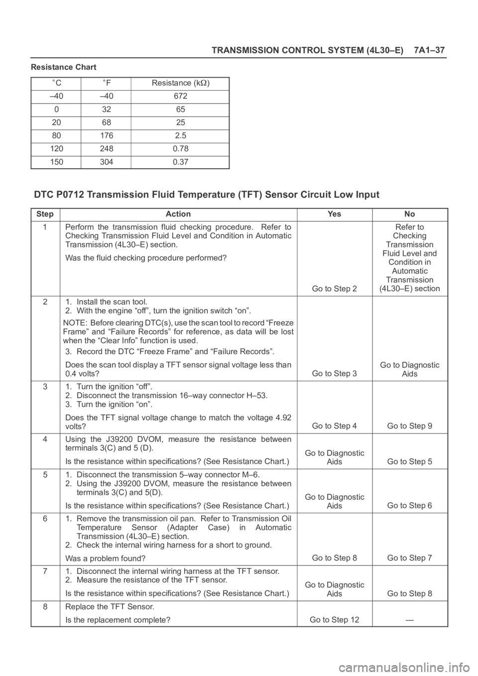
Resistance Chart
CFResistance (k)
–40–40672
03265
206825
801762.5
1202480.78
1503040.37
DTC P0712 Transmission Fluid Temperature (TFT) Sensor Circuit Low Input
StepActionYe sNo
1Perform the transmission fluid checking procedure. Refer to
Checking Transmission Fluid Level and Condition in Automatic
Transmission (4L30–E) section.
Was the fluid checking procedure performed?
Go to Step 2
Refer to
Checking
Transmission
Fluid Level and
Condition in
Automatic
Transmission
(4L30–E) section
21. Install the scan tool.
2. With the engine “off”, turn the ignition switch “on”.
NOTE: Before clearing DTC(s), use the scan tool to record “Freeze
Frame” and “Failure Records” for reference, as data will be lost
when the “Clear Info” function is used.
3. Record the DTC “Freeze Frame” and “Failure Records”.
Does the scan tool display a TFT sensor signal voltage less than
0.4 volts?
Go to Step 3
Go to Diagnostic
Aids
31. Turn the ignition “off”.
2. Disconnect the transmission 16–way connector H–53.
3. Turn the ignition “on”.
Does the TFT signal voltage change to match the voltage 4.92
volts?
Go to Step 4Go to Step 9
4Using the J39200 DVOM, measure the resistance between
terminals 3(C) and 5 (D).
Is the resistance within specifications? (See Resistance Chart.)
Go to Diagnostic
Aids
Go to Step 5
51. Disconnect the transmission 5–way connector M–6.
2. Using the J39200 DVOM, measure the resistance between
terminals 3(C) and 5(D).
Is the resistance within specifications? (See Resistance Chart.)
Go to Diagnostic
Aids
Go to Step 6
61. Remove the transmission oil pan. Refer to Transmission Oil
Temperature Sensor (Adapter Case) in Automatic
Transmission (4L30–E) section.
2. Check the internal wiring harness for a short to ground.
Was a problem found?
Go to Step 8Go to Step 7
71. Disconnect the internal wiring harness at the TFT sensor.
2. Measure the resistance of the TFT sensor.
Is the resistance within specifications? (See Resistance Chart.)
Go to Diagnostic
Aids
Go to Step 8
8Replace the TFT Sensor.
Is the replacement complete?
Go to Step 12—
Page 2285 of 6000

7A1–40
TRANSMISSION CONTROL SYSTEM (4L30–E)
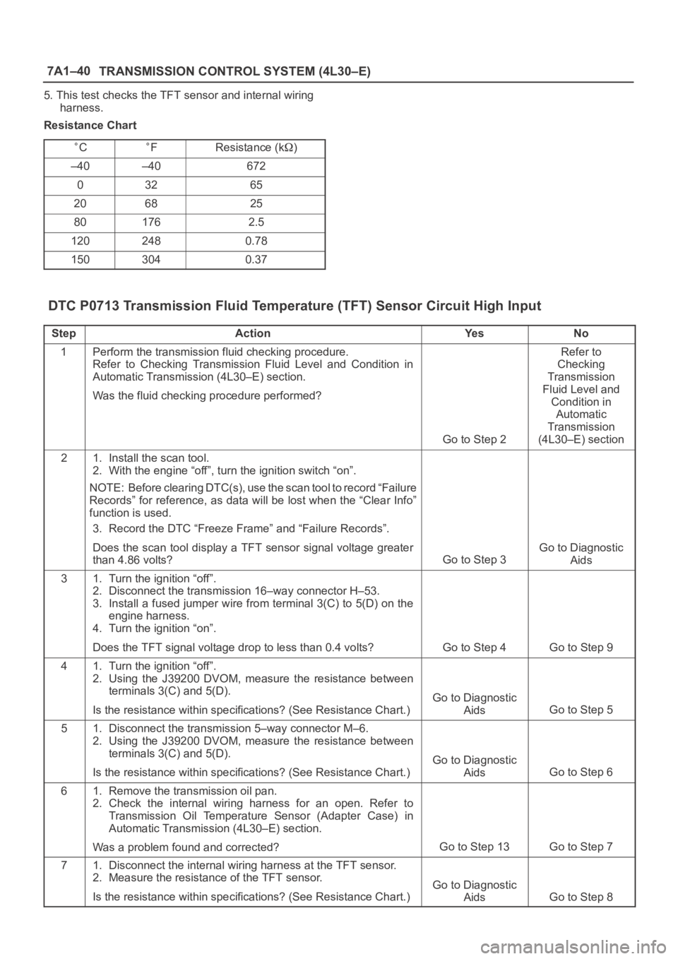
5. This test checks the TFT sensor and internal wiring
harness.
Resistance Chart
CFResistance (k)
–40–40672
03265
206825
801762.5
1202480.78
1503040.37
DTC P0713 Transmission Fluid Temperature (TFT) Sensor Circuit High Input
StepActionYe sNo
1Perform the transmission fluid checking procedure.
Refer to Checking Transmission Fluid Level and Condition in
Automatic Transmission (4L30–E) section.
Was the fluid checking procedure performed?
Go to Step 2
Refer to
Checking
Transmission
Fluid Level and
Condition in
Automatic
Transmission
(4L30–E) section
21. Install the scan tool.
2. With the engine “off”, turn the ignition switch “on”.
NOTE: Before clearing DTC(s), use the scan tool to record “Failure
Records” for reference, as data will be lost when the “Clear Info”
function is used.
3. Record the DTC “Freeze Frame” and “Failure Records”.
Does the scan tool display a TFT sensor signal voltage greater
than 4.86 volts?
Go to Step 3
Go to Diagnostic
Aids
31. Turn the ignition “off”.
2. Disconnect the transmission 16–way connector H–53.
3. Install a fused jumper wire from terminal 3(C) to 5(D) on the
engine harness.
4. Turn the ignition “on”.
Does the TFT signal voltage drop to less than 0.4 volts?
Go to Step 4Go to Step 9
41. Turn the ignition “off”.
2. Using the J39200 DVOM, measure the resistance between
terminals 3(C) and 5(D).
Is the resistance within specifications? (See Resistance Chart.)
Go to Diagnostic
Aids
Go to Step 5
51. Disconnect the transmission 5–way connector M–6.
2. Using the J39200 DVOM, measure the resistance between
terminals 3(C) and 5(D).
Is the resistance within specifications? (See Resistance Chart.)
Go to Diagnostic
Aids
Go to Step 6
61. Remove the transmission oil pan.
2. Check the internal wiring harness for an open. Refer to
Transmission Oil Temperature Sensor (Adapter Case) in
Automatic Transmission (4L30–E) section.
Was a problem found and corrected?
Go to Step 13Go to Step 7
71. Disconnect the internal wiring harness at the TFT sensor.
2. Measure the resistance of the TFT sensor.
Is the resistance within specifications? (See Resistance Chart.)
Go to Diagnostic
Aids
Go to Step 8