oil OPEL FRONTERA 1998 Workshop Manual
[x] Cancel search | Manufacturer: OPEL, Model Year: 1998, Model line: FRONTERA, Model: OPEL FRONTERA 1998Pages: 6000, PDF Size: 97 MB
Page 2521 of 6000
7C–12CLUTCH
Driven Plate Assembly
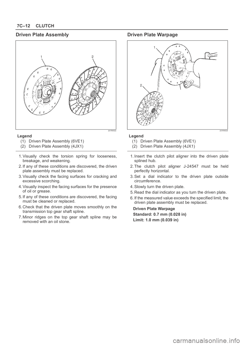
201RW033
Legend
(1) Driven Plate Assembly (6VE1)
(2) Driven Plate Assembly (4JX1)
1. Visually check the torsion spring for looseness,
breakage, and weakening.
2. If any of these conditions are discovered, the driven
plate assembly must be replaced.
3. Visually check the facing surfaces for cracking and
excessive scorching.
4. Visually inspect the facing surfaces for the presence
of oil or grease.
5. If any of these conditions are discovered, the facing
must be cleaned or replaced.
6. Check that the driven plate moves smoothly on the
transmission top gear shaft spline.
7. Minor ridges on the top gear shaft spline may be
removed with an oil stone.
Driven Plate Warpage
201RW034
Legend
(1) Driven Plate Assembly (6VE1)
(2) Driven Plate Assembly (4JX1)
1. Insert the clutch pilot aligner into the driven plate
splined hub.
2. The clutch pilot aligner J-24547 must be held
perfectly horizontal.
3. Set a dial indicator to the driven plate outside
circumference.
4. Slowly turn the driven plate.
5. Read the dial indicator as you turn the driven plate.
6. If the measured value exceeds the specified limit, the
driven plate assembly must be replaced.
Driven Plate Warpage
Standard: 0.7 mm (0.028 in)
Limit: 1.0 mm (0.039 in)
Page 2523 of 6000
7C–14CLUTCH
Release Bearing
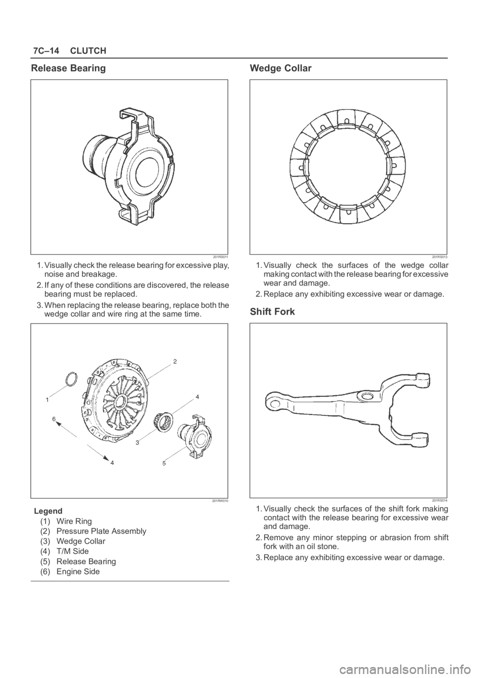
201RS011
1. Visually check the release bearing for excessive play,
noise and breakage.
2. If any of these conditions are discovered, the release
bearing must be replaced.
3. When replacing the release bearing, replace both the
wedge collar and wire ring at the same time.
201RW010
Legend
(1) Wire Ring
(2) Pressure Plate Assembly
(3) Wedge Collar
(4) T/M Side
(5) Release Bearing
(6) Engine Side
Wedge Collar
201RS013
1. Visually check the surfaces of the wedge collar
making contact with the release bearing for excessive
wear and damage.
2. Replace any exhibiting excessive wear or damage.
Shift Fork
201RS014
1. Visually check the surfaces of the shift fork making
contact with the release bearing for excessive wear
and damage.
2. Remove any minor stepping or abrasion from shift
fork with an oil stone.
3. Replace any exhibiting excessive wear or damage.
Page 2524 of 6000
CLUTCH7C–15
Installation
To install, follow the removal steps in the reverse order,
noting the following points:
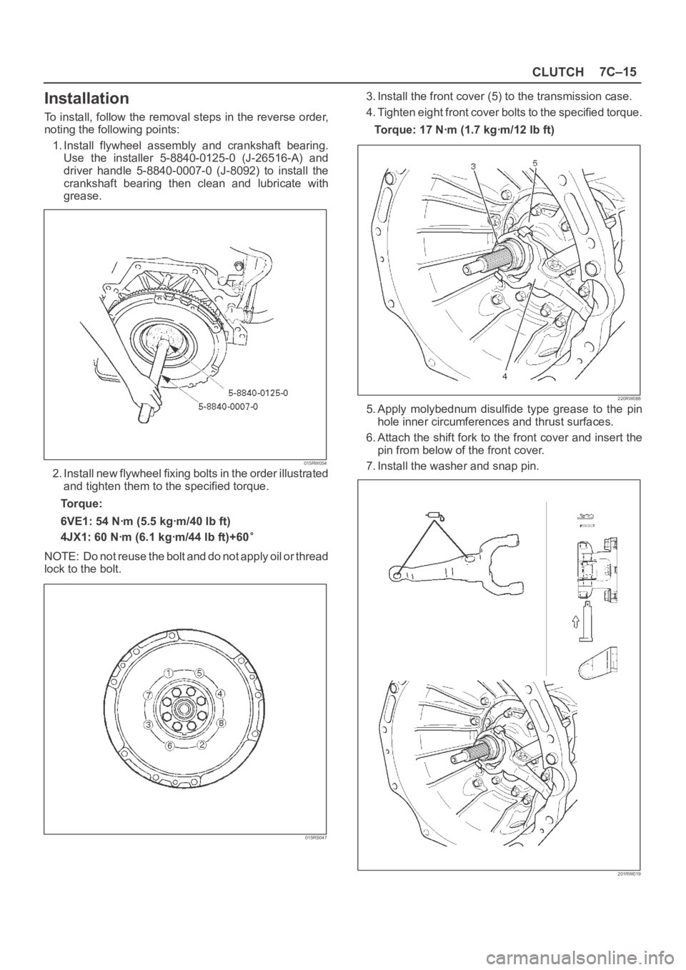
1. Install flywheel assembly and crankshaft bearing.
Use the installer 5-8840-0125-0 (J-26516-A) and
driver handle 5-8840-0007-0 (J-8092) to install the
crankshaft bearing then clean and lubricate with
grease.
015RW054
2. Install new flywheel fixing bolts in the order illustrated
and tighten them to the specified torque.
Torque:
6VE1: 54 Nꞏm (5.5 kgꞏm/40 lb ft)
4JX1: 60 Nꞏm (6.1 kgꞏm/44 lb ft)+60
NOTE: Do not reuse the bolt and do not apply oil or thread
lock to the bolt.
015RS047
3. Install the front cover (5) to the transmission case.
4. Tighten eight front cover bolts to the specified torque.
Torque: 17 Nꞏm (1.7 kgꞏm/12 lb ft)
220RW088
5. Apply molybednum disulfide type grease to the pin
hole inner circumferences and thrust surfaces.
6. Attach the shift fork to the front cover and insert the
pin from below of the front cover.
7. Install the washer and snap pin.
201RW019
Page 2526 of 6000
CLUTCH7C–17
Clutch Control
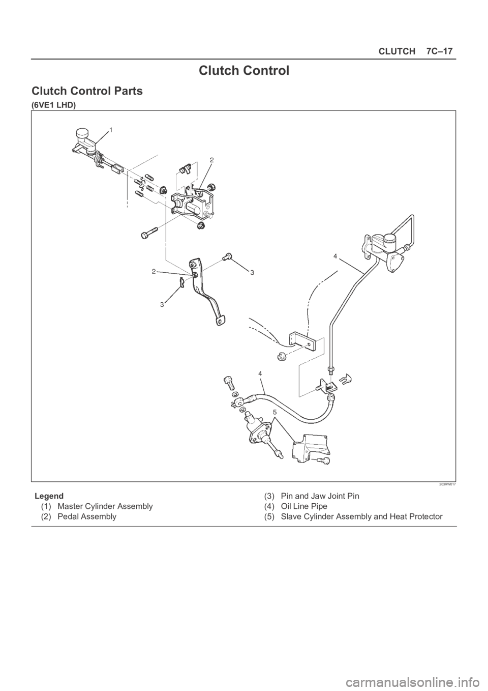
Clutch Control Parts
(6VE1 LHD)
203RW017
Legend
(1) Master Cylinder Assembly
(2) Pedal Assembly(3) Pin and Jaw Joint Pin
(4) Oil Line Pipe
(5) Slave Cylinder Assembly and Heat Protector
Page 2527 of 6000
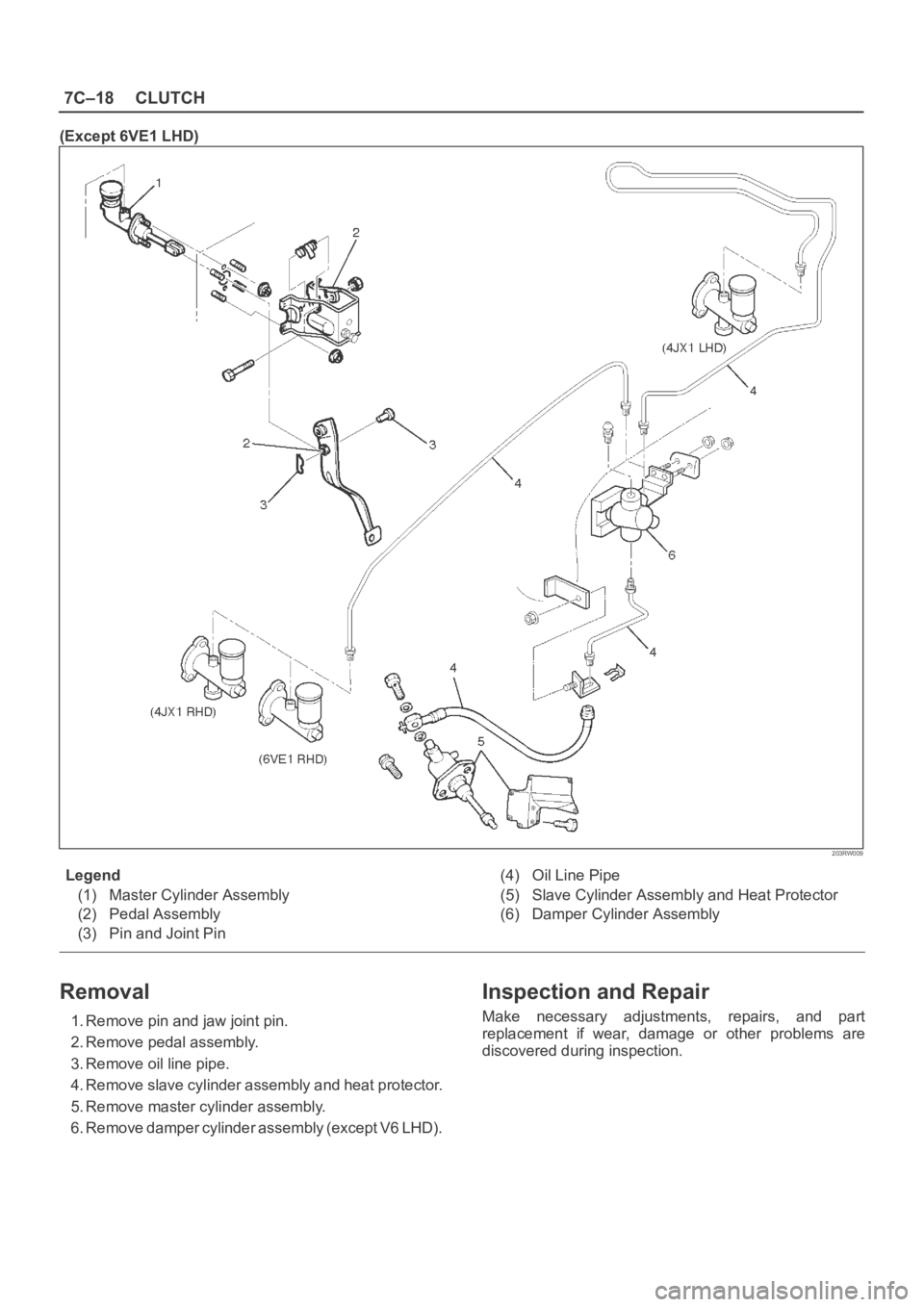
7C–18CLUTCH
(Except 6VE1 LHD)
203RW009
Legend
(1) Master Cylinder Assembly
(2) Pedal Assembly
(3) Pin and Joint Pin (4) Oil Line Pipe
(5) Slave Cylinder Assembly and Heat Protector
(6) Damper Cylinder Assembly
Removal
1. Remove pin and jaw joint pin.
2. Remove pedal assembly.
3. Remove oil line pipe.
4. Remove slave cylinder assembly and heat protector.
5. Remove master cylinder assembly.
6. Remove damper cylinder assembly (except V6 LHD).
Inspection and Repair
Make necessary adjustments, repairs, and part
replacement if wear, damage or other problems are
discovered during inspection.
Page 2528 of 6000

CLUTCH7C–19
Installation
1. Install damper cylinder assembly (except V6 LHD).
2. Install master cylinder assembly.
3. Install slave cylinder assembly and heat protector.
4. Install oil line pipe.
5. Install pedal assembly.
6. Install pin and jaw joint pin.
Adjustment
Clutch Pedal Adjustment
1. Loosen the clutch pedal adjusting bolt so that there is
enough gap between the clutch pedal and the
adjusting bolt to allow push rod adjustment.
203RW011
Legend
(1) Push Rod
(2) Adjusting Bolt
2. Loosen clutch master cylinder push rod lock nut. Turn
push rod by hand to set clutch pedal height (5) to
within specification.
Clutch pedal height (5):
LHD: 217 mm – 227 mm (8.543 in – 8.937 in)
RHD:
(6VE1) 238.5 mm – 248.5 mm (9.390 in – 9.783 in)
(4JX1) 231 mm – 241 mm (9.094 in – 9.488 in)
203RW004
Legend
(3) Floor Panel
(4) Pedal Free Play
(5) Clutch Pedal Height
3. Tighten push rod lock nut.
4. Adjusting bolt adjustment.
1. Turn the adjusting bolt until it just touches the
clutch pedal arm.
203RW012
Legend
(6) Blacket
(7) Adjusting Bolt
(8) Clutch Pedal Arm
Page 2532 of 6000

CLUTCH7C–23
Disassembly
(4JX1)
1. Remove damper cylinder assembly and gasket.
2. Remove push rod damper.
NOTE: The master cylinder assembly cannot be
disassembled because of point–staked rod stopper.
Inspection and Repair
Clean and inspect the removed parts.
Make necessary parts replacement if any abnormalities
such as wear, oil leaks or other damage are found through
inspection.
Reassembly
To reassemble, follow the disassembly steps in the
reverse order, noting the following points:
1.Push rod set length
RHD: 117.5 mm (4.626 in)
LHD: 119 mm (4.685 in)
2.Push rod nut torque
17 Nꞏm (1.7 kgꞏm/12 Ib ft)
3.Damper cylinder torque
47 Nꞏm (4.8 kgꞏm/35 Ib ft)
Page 2557 of 6000
8A–18LIGHTING SYSTEM
Lighting Switch (Combination Switch)
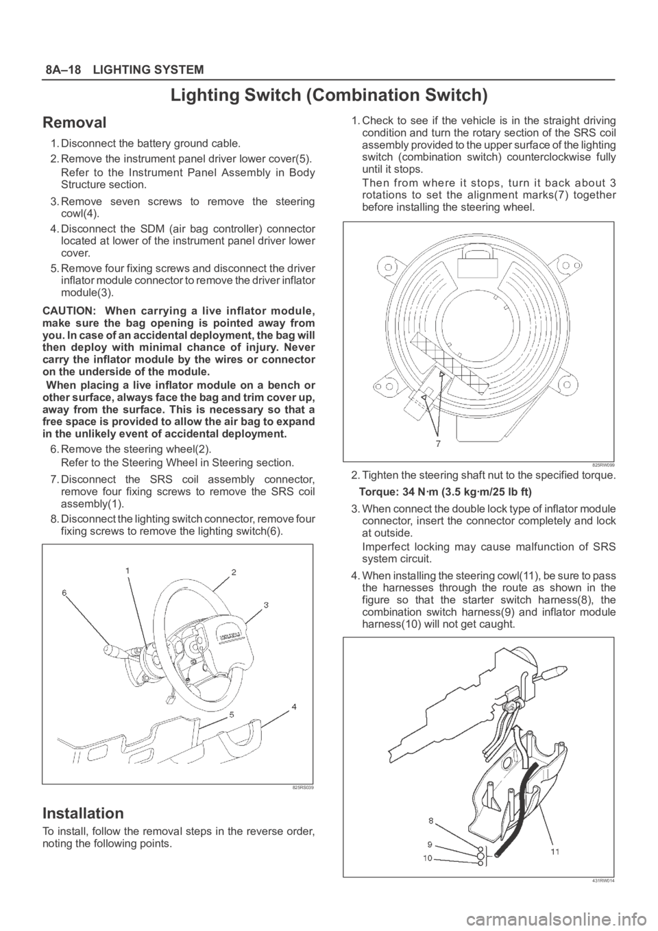
Removal
1. Disconnect the battery ground cable.
2. Remove the instrument panel driver lower cover(5).
Refer to the Instrument Panel Assembly in Body
Structure section.
3. Remove seven screws to remove the steering
cowl(4).
4. Disconnect the SDM (air bag controller) connector
located at lower of the instrument panel driver lower
cover.
5. Remove four fixing screws and disconnect the driver
inflator module connector to remove the driver inflator
module(3).
CAUTION: When carrying a live inflator module,
make sure the bag opening is pointed away from
y o u . I n c a s e o f a n a c c i d e n t a l d e p l o y m e n t , t h e b a g w i l l
then deploy with minimal chance of injury. Never
carry the inflator module by the wires or connector
on the underside of the module.
When placing a live inflator module on a bench or
other surface, always face the bag and trim cover up,
away from the surface. This is necessary so that a
free space is provided to allow the air bag to expand
in the unlikely event of accidental deployment.
6. Remove the steering wheel(2).
Refer to the Steering Wheel in Steering section.
7. Disconnect the SRS coil assembly connector,
remove four fixing screws to remove the SRS coil
assembly(1).
8. Disconnect the lighting switch connector, remove four
fixing screws to remove the lighting switch(6).
825RS039
Installation
To install, follow the removal steps in the reverse order,
noting the following points.1. Check to see if the vehicle is in the straight driving
condition and turn the rotary section of the SRS coil
assembly provided to the upper surface of the lighting
switch (combination switch) counterclockwise fully
until it stops.
Then from where it stops, turn it back about 3
rotations to set the alignment marks(7) together
before installing the steering wheel.
825RW099
2. Tighten the steering shaft nut to the specified torque.
Torque: 34 Nꞏm (3.5 kgꞏm/25 lb ft)
3. When connect the double lock type of inflator module
connector, insert the connector completely and lock
at outside.
Imperfect locking may cause malfunction of SRS
system circuit.
4. When installing the steering cowl(11), be sure to pass
the harnesses through the route as shown in the
figure so that the starter switch harness(8), the
combination switch harness(9) and inflator module
harness(10) will not get caught.
431RW014
Page 2568 of 6000
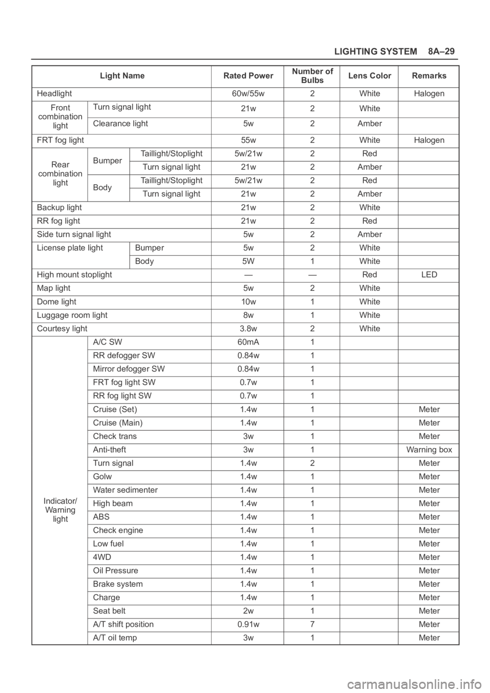
LIGHTING SYSTEM8A–29
Light NameRated PowerNumber of
BulbsLens ColorRemarks
Headlight60w/55w2WhiteHalogen
FrontTurn signal light21w2Whitecombination
lightClearance light5w2Amber
FRT fog light55w2WhiteHalogen
Taillight/Stoplight5w/21w2Red
RearBumperTurn signal light21w2Ambercombination
lightTaillight/Stoplight5w/21w2RedBodyTurn signal light21w2Amber
Backup light21w2White
RR fog light21w2Red
Side turn signal light5w2Amber
License plate lightBumper5w2White
Body5W1White
High mount stoplight——RedLED
Map light5w2White
Dome light10w1White
Luggage room light8w1White
Courtesy light3.8w2White
A/C SW60mA1
RR defogger SW0.84w1
Mirror defogger SW0.84w1
FRT fog light SW0.7w1
RR fog light SW0.7w1
Cruise (Set)1.4w1Meter
Cruise (Main)1.4w1Meter
Check trans3w1Meter
Anti-theft3w1Warning box
Turn signal1.4w2Meter
Golw1.4w1Meter
Water sedimenter1.4w1Meter
Indicator/High beam1.4w1MeterWa rnin g
lightABS1.4w1Meter
Check engine1.4w1Meter
Low fuel1.4w1Meter
4WD1.4w1Meter
Oil Pressure1.4w1Meter
Brake system1.4w1Meter
Charge1.4w1Meter
Seat belt2w1Meter
A/T shift position0.91w7Meter
A/T oil temp3w1Meter
Page 2585 of 6000

8C–2ENTERTAINMENT
Cigarette Lighter
General Description
When the cigarette lighter is pushed in with the starter
s w i t c h a t e i t h e r “ A C C ” o r “ O N ” p o s i t i o n , a c i r c u i t i s f o r m e d
in the cigarette lighter case to heat the lighter coil.
The cigarette lighter is sprung back to its original position
after the lighter coil is heated.
Removal
1. Disconnect the battery ground cable.
2. Remove the lower cluster assembly(1).
Refer to the Instrument Panel Assembly removal
steps in Body Structure section.
3. Disconnect the connectors, remove the socket of the
illumination light, the retaining ring(7), the outer
case(6), the cigarette lighter(3) and socket(4), the
bezel(5) and then remove the cigarette lighter
assembly(2).
826RS007
Installation
To install, follow the removal steps in the reverse order,
noting the following point.
1. When installing the bezel, align the projected portion
of the socket with the notch of the bezel.