oil OPEL FRONTERA 1998 Workshop Manual
[x] Cancel search | Manufacturer: OPEL, Model Year: 1998, Model line: FRONTERA, Model: OPEL FRONTERA 1998Pages: 6000, PDF Size: 97 MB
Page 2343 of 6000

MANUAL TRANSMISSION7B–25
2. Using a plastic hammer, carefully tap the front
cover.
220RW017
9. Remove the front cover oil seal.
1. Mount the front cover through the aluminum plate
in a vise.
2. Using screwdriver, remove oil seal (1).
220RW019
10. Remove the transmission case.
1. Using a snap ring expander, remove the 2 snap
rings (1)(2).
226RW004
2. Using a plastic hammer, carefully tap the
transmission case.
220RW020
Page 2360 of 6000

7B–42MANUAL TRANSMISSION
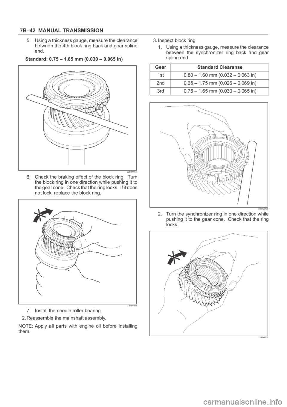
5. Using a thickness gauge, measure the clearance
between the 4th block ring back and gear spline
end.
Standard: 0.75 – 1.65 mm (0.030 – 0.065 in)
226RW064
6. Check the braking effect of the block ring. Turn
the block ring in one direction while pushing it to
the gear cone. Check that the ring locks. If it does
not lock, replace the block ring.
226RW060
7. Install the needle roller bearing.
2. Reassemble the mainshaft assembly.
NOTE: Apply all parts with engine oil before installing
them.3. Inspect block ring
1. Using a thickness gauge, measure the clearance
between the synchronizer ring back and gear
spline end.
Gear
Standard Clearanse
1st0.80–1.60mm (0.032–0.063in)
2nd0.65–1.75mm (0.026–0.069in)
3rd0.75–1.65mm (0.030–0.065in)
226RW105
2. Turn the synchronizer ring in one direction while
pushing it to the gear cone. Check that the ring
locks.
226RW106
Page 2369 of 6000

MANUAL TRANSMISSION7B–51
17. Install the front cover.
1. Using installer 5–8840–2557–0 (J–42801), grip
5–8840–0007–0 (J–8092) and a hammer, drive in
a new oil seal.
Drive in depth (from cover end): 11.7
0.5 mm
(0.46
0.02 in)
2. Apply grease to the seal lip.
220RW113
18. Install the transfer adapter.
1. Using installer 5–8840–2558–0 (J –42802), and a
hammer drive in a new oil seal.
Drive in depth (from transfer adapter):
10.95
0.5 mm (0.431 0.02 in)
2. Apply grease to the oil seal lip.
220RW114
3. Install the oil receiver pipe.
220RW011
4. Install the reverse restrict to the transfer adapter.
226RW059
Page 2374 of 6000

7B–56MANUAL TRANSMISSION
24. Install the interlock parts.
1. Using a screwdriver and hammer, 2 new shift rod
snap rings to the 1st–2nd and 3rd–4th shift rod.
226RW051
2. Install the 3 shift detent ball and springs to the
intermediate plate.
226RW049
3. Clean up the plug hole.
4. Apply sealant to the plug threads.
sealant: THREE BOND 1344 or equivalent5. Using a torx socket wrench(T40), install and
torque the 4 plugs.
Torque: 19 Nꞏm (1.9 kgꞏm/14 lb ft)
226RW050
25. Install mainshaft assembly.
NOTE: Coat all parts with gear oil before installing them.
1. Using a plastic hammer, tap the 5th-reverse shift
rod at the reverse shift.
226RW180
Page 2381 of 6000

MANUAL TRANSMISSION7B–63
3. Stand the transmission by the wood blocks.
4. Using a plastic hammer, tap the transmission
case and attach it to the intermediate plate.
NOTE: Be careful not to add over force to bearing.
220RW022
5. Using a snap ring expander, install the front
bearing shaft snap ring (1) and counter gear shaft
bearing snap ring (2).
226RW004
6. Turn over the transmission.
35. Install the front cover.
1. Clean up the fitting surface.
2. Apply recommended liquid gasket (THREE
BOND 1281 or equivalent), as shown.NOTE:
Don’t dry the liquid gasket.
220RW025
3. Clean up and dry the bolts.
4. Apply thread sealant (THREE BOND 1344 or
equivalent) to the 8 bolts.
5. Using 8 bolts, install the front cover to the
transmission case.
Torque: 17 Nꞏm (1.7 kgꞏm/12 lb ft)
NOTE:
Tighten the all bolts evenly.
Be careful not to damage the oil seal.
220RW018
Page 2382 of 6000

7B–64MANUAL TRANSMISSION
6. Check that the top gear shaft and mainshaft
rotate.
36. Install the transfer adapter.
1. Clean up the fitting surface.
2. Apply recommended liquid gasket (THREE
BOND 1281 or equivalent), as shown.
NOTE:
Don’t dry the liquid gasket.
220RW026
3. Using a plastic hammer, tap the transfer adapter
and attach it to the intermediate plate.
220RW034
4. Using 10 bolts, install the transfer adapter.
Torque: 37 Nꞏm (3.8 kgꞏm/27 lb ft)
NOTE:
Tighten the all bolts evenly.
Don’t damage the lip of the oil seal.
Install the wire clamp (9) to the transfer adapter.
220RW083
37. Install the gear control box.
1. Align the projection of the shift lever housing to
the shaft rod groove, and install the gear control
rod.
230RW003
Page 2385 of 6000

MANUAL TRANSMISSION7B–67
41. Install the drain plug and filler plug.
1. Install the drain plug (1) through the new gasket.
Torque: 37 Nꞏm (3.8 kgꞏm/27 lb ft)
2. Install the filler plug (2) through the new gasket.
Reference: Plug after the gear oil fill in.
Torque: 37 Nꞏm (3.8 kgꞏm/27 lb ft)
(6VE1)
220RW007
Page 2386 of 6000

7B–68MANUAL TRANSMISSION
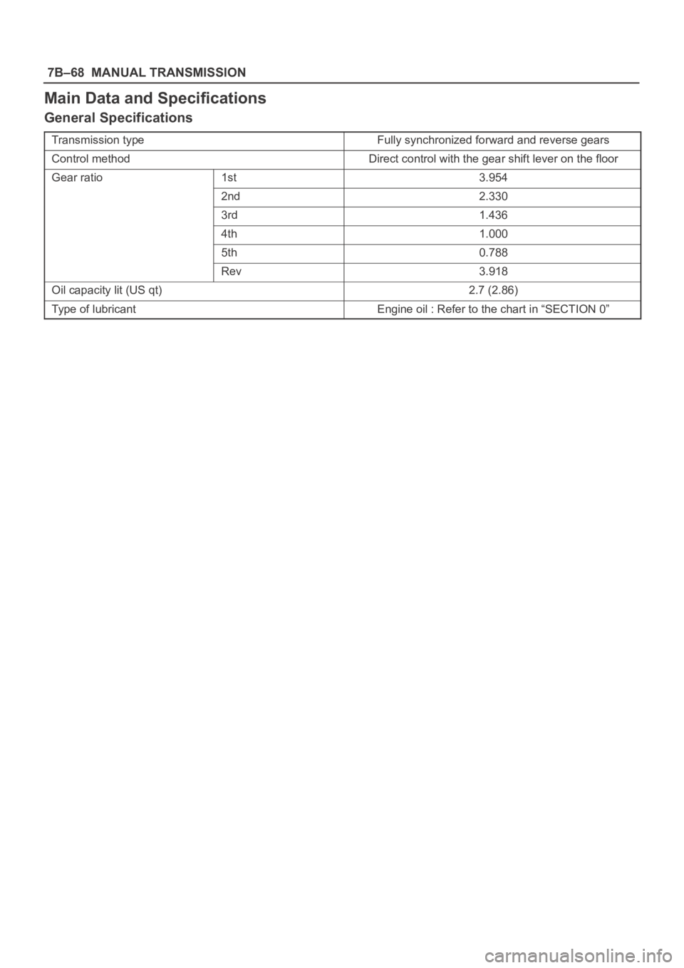
Main Data and Specifications
General Specifications
Transmission typeFully synchronized forward and reverse gears
Control methodDirect control with the gear shift lever on the floor
Gear ratio1st3.954
2nd2.330
3rd1.436
4th1.000
5th0.788
Rev3.918
Oil capacity lit (US qt)2.7 (2.86)
Type of lubricantEngine oil : Refer to the chart in “SECTION 0”
Page 2390 of 6000

7B–72MANUAL TRANSMISSION
Special Tools
ILLUSTRATIONTOOL NO.
TOOL NAME
5–8840–2550–0
(J–42794)
Gear spline pieace
remover
5–8840–2551–0
(J–42795)
Center bearing remover
5–8840–2560–0
(J–42988)
Attachment
5–8840–2552–0
(J–42796)
Counter gear shaft
center bearing installer
5–8840–2553–0
(J–42797)
Clutch hub (No.2)
installer
5–8840–2554–0
(J–42798)
Clutch hub (No.1)
installer
ILLUSTRATIONTOOL NO.
TOOL NAME
5–8840–2555–0
(J–42799)
Installer
5–8840–2556–0
(J–42800)
Counter gear shaft front
bearing installer
5–8840–2559–0
(J–42904)
Top gear shaft front
bearing installer
5–8840–2557–0
(J–42801)
Front rerainer oil seal
installer
5–8840–2558–0
(J–42802)
Transfer adapter oil seal
installer
5–8840–0007–0
(J–8092)
Driver handle
Page 2517 of 6000

7C–8CLUTCH
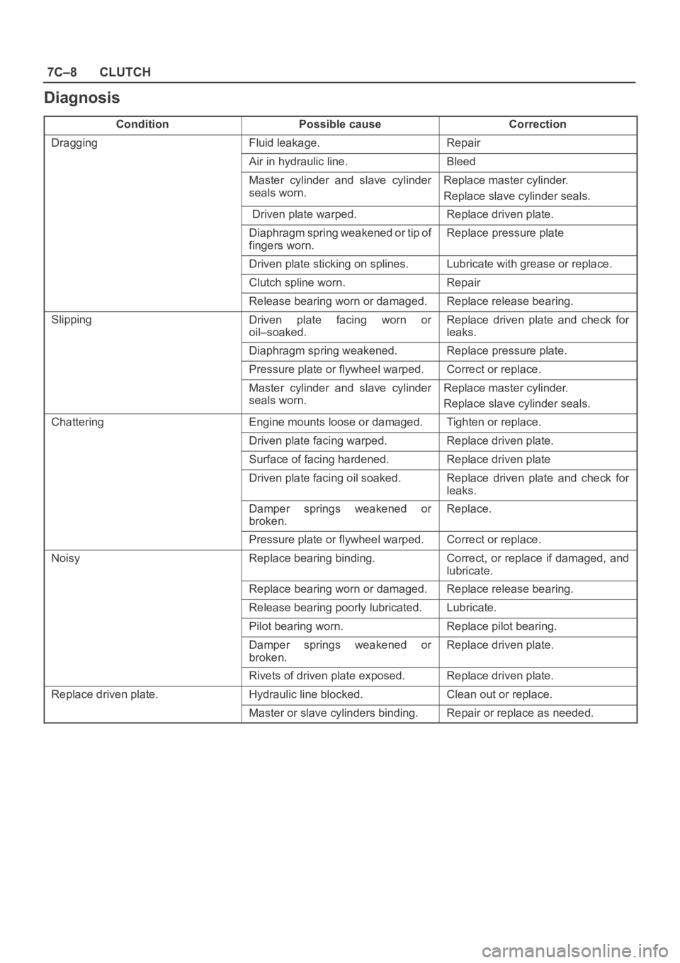
Diagnosis
ConditionPossible causeCorrection
DraggingFluid leakage.Repair
Air in hydraulic line.Bleed
Master cylinder and slave cylinder
seals worn. Replace master cylinder.
Replace slave cylinder seals.
Driven plate warped.Replace driven plate.
Diaphragm spring weakened or tip of
fingers worn. Replace pressure plate
Driven plate sticking on splines.Lubricate with grease or replace.
Clutch spline worn. Repair
Release bearing worn or damaged.Replace release bearing.
SlippingDriven plate facing worn or
oil–soaked.Replace driven plate and check for
leaks.
Diaphragm spring weakened.Replace pressure plate.
Pressure plate or flywheel warped.Correct or replace.
Master cylinder and slave cylinder
seals worn.Replace master cylinder.
Replace slave cylinder seals.
ChatteringEngine mounts loose or damaged.Tighten or replace.
Driven plate facing warped.Replace driven plate.
Surface of facing hardened.Replace driven plate
Driven plate facing oil soaked. Replace driven plate and check for
leaks.
Damper springs weakened or
broken. Replace.
Pressure plate or flywheel warped.Correct or replace.
NoisyReplace bearing binding.Correct, or replace if damaged, and
lubricate.
Replace bearing worn or damaged. Replace release bearing.
Release bearing poorly lubricated. Lubricate.
Pilot bearing worn.Replace pilot bearing.
Damper springs weakened or
broken.Replace driven plate.
Rivets of driven plate exposed.Replace driven plate.
Replace driven plate.Hydraulic line blocked.Clean out or replace.
Master or slave cylinders binding.Repair or replace as needed.