ECU OPEL FRONTERA 1998 Repair Manual
[x] Cancel search | Manufacturer: OPEL, Model Year: 1998, Model line: FRONTERA, Model: OPEL FRONTERA 1998Pages: 6000, PDF Size: 97 MB
Page 979 of 6000
6A–23
ENGINE MECHANICAL
6. Install idle pulley assembly and tighten the fixing bolt
to the specified torque.
Torque : 52 Nꞏm (5.3 Kgꞏm/38.4 lb ft)
7. Install fan pulley and bracket assembly and tighten
the fixing bolts and nut to the specified torque.
Torque : 22 Nꞏm (2.2 Kgꞏm/16.2 lb ft)
8. Install drive belt by pushing down the auto tensioner
using spanner as shown in the removal step of drive
belt.
9. Install cooling fan clutch assembly and tighten the
fixing bolts to the specified torque.
Torque : 10 Nꞏm (1.0 Kgꞏm/88.5 lb in)
10. Install upper fan guide and clip both side and tighten
the fixing bolts to the specified torque.
Torque : 4 Nꞏm (0.4 Kgꞏm/35.4 lb in)
11. Install engine harness and tighten the fixing bolts of
the retaining clip and brackets to the specified torque.
Torque : 4 Nꞏm (0.4 Kgꞏm/35.4 lb in)
12. Connect radiator upper and lower hoses and clip
them securely.
13. Connect wiring connectors and bonding cable of
those which were disconnected in the removal step.
14. Install air cleaner element and air cleaner duct
assembly, and the clip both end securely.
15. Connect MAF sensor connector, IAT sensor
connector and PCV hose.
16. Install engine cover mating with the dowels.
Page 987 of 6000
6A–31
ENGINE MECHANICAL
2. Align the alignment mark on the RH bank
camshaft drive gear pulley (2) to the alignment
mark of the cylinder head cover RH (3).
3. Align the alignment mark (white line) on the timing
belt (1) with alignment mark on the RH bank
camshaft drive gear pulley (2) (on the left side as
viewed from the front of the vehicle) and put the
timing belt on the camshaft drive gear pulley.
Secure the belt with a double clip or equivalent
clip.
014RW00004
Legend
(1) Alignment Mark on Timing Belt (White line).
(2) Alignment Mark on Camshaft Drive Gear
Pulley.
(3) Alignemnt Mark on Cylinder Head Cover RH.
4. Align the alignment mark on the LH bank
camshaft drive gear pulley (2) to the alignment
mark of the cylinder head cover LH (3).
5. Align the alignment mark (white line) on the timing
belt (1) with the alignment mark on the LH bank
camshaft drive gear pulley (2).
When aligning the timing marks, use a wrench to
turn the camshaft drive gear pulley, then set the
timing mark between timing belt and camshaft
drive gear pulley and put the timing belt on the
camshaft drive gear pulley.
Secure the belt with a double clip or equivalent
clip.
NOTE: It is recommended for easy installation that the
belt be secured with a double clip or equivalent clip after
it is installed the timing belt to each pulley.
014RW00005
Legend
(1) Alignment Mark on Timing Belt (White line).
(2) Alignment Mark on Camshaft Drive Gear
Pulley.
(3) Alignemnt Mark on Cylinder Head Cover LH.
6. Install crankshaft pulley temporarily and tighten
center bolt by hand (do not use a wrench).
Turn the crankshaft pulley clockwise to give some
belt slack between the crankshaft timing pulley
and the RH bank camshaft drive gear pulley.
2. Install pusher and tighten bolt to the specified torque.
Torque : 25 Nꞏm (2.5 Kgꞏm/18 lb ft)
1. Install the pusher while pushing the tension pulley
to the belt.
2. Pull out pin from the pusher.
NOTE: When reusing the pusher, press the pusher with
approximately 100Kg to retract the rod, and insert a pin
(1.4 mm piano wire).
014RW011
Page 1064 of 6000
ENGINE COOLING6B–11
Cap tester: 5–8840–0277–0
Adapter: 5–8840–2603–0
110RS005
Installation
1. Install rubber cushions on both sides of radiator
bottom.
2. Install radiator assembly with hose, taking care not to
damage the radiator core with a fan blade.
3. Install bracket (6) and support the radiator upper tank
with the bracket (5) and secure the radiator.
4. Connect reserve tank hose (4).
5. Install lower fan guide (3).
6. Connect radiator inlet hose and outlet hose to the
engine.
7. Connect oil cooler hose (1) to automatic
transmission.
110RW004
8. Connect battery ground cable.
9. Pour engine coolant up to filler neck of radiator, and
up to MAX mark of reserve tank.
111 R S 0 0 1Important operation (in case of 100% engine coolant
change) procedure for filling with engine coolant.
1. Make sure that the engine is cool.
2. Open radiator cap pour coolant up to filler neck.
3. Pour coolant into reservoir tank up to “MAX” line.
4. Tighten radiator cap and start the engine. After
idling for 2 to 3 minutes, stop the engine and
reopen radiator cap. If the water level is lower,
replenish.
WARNING: WHEN THE COOLANT IS HEATED TO A
HIGH TEMPERATURE, BE SURE NOT TO LOOSEN
OR REMOVE THE RADIATOR CAP. OTHERWISE YOU
MIGHT GET SCALDED BY HOT VAPOR OR BOILING
WATER. TO OPEN THE RADIATOR CAP, PUT A
PIECE OF THICK CLOTH ON THE CAP AND LOOSEN
THE CAP SLOWLY TO REDUCE THE PRESSURE
WHEN THE COOLANT HAS BECOME COOLER.
5. After tightening radiator cap, warm up the engine
at about 2000 rpm. Set heater adjustment to the
highest temperature position, and let the coolant
circulate also into heater water system.
6. Check to see the thermostat has opened through
the needle position of water thermometer,
conduct a 5–minute idling again and stop the
engine.
7. When the engine has been cooled, check filler
neck for water level and replenish if required.
Should extreme shortage of coolant is found,
check the cooling system and reservoir tank hose
for leakage.
8. Pour coolant into reservoir tank up tp “MAX” line.
Page 1077 of 6000
6C–10
ENGINE FUEL
Reuse of Quick–Connector
(Delivery Pipe)
Replace the pipe and connector if scratch, dent or
crack is found.
Remove mud and dust from the pipe and make sure
that the end including spool is free of defects, such as
scratch, rust, and dent, which may cause poor
sealability. If defective, replace with a new pipe.
If the retainer removed according to the removal step
above is attached to the pipe, clean and insert it
straight into the quick-connector till it clicks. After it
clicks, try pulling it out to make sure that it is not drawn
and is securely locked.
NOTE: The retainer, once removed from the pipe, cannot
be reused. Just replace with a new retainer. Insert the
new retainer into the connector side until it clicks, and
connect the pipe as inserting it into the retainer until it
clicks.
141RW018
(Return Pipe)
Replace the pipe and connector if scratch, dent or
crack is found.
Remove mud or dust from the pipe and make sure
that the end including spool is free from defects, such
as scratch, rust, and dent, which may cause poor
sealability. If defective, replace with a new pipe.
After cleaning the pipe, insert it straight into the
connector until it clicks. After it clicks, try pulling it out
to make sure that it is not drawn and is securely
locked.
141RW017
Assembling Advice
Application of engine oil or light oil to the pipe facilitates
connecting work. The work should be started immediately
after lubrication, since dust may stick to the pipe surface
to cause poor sealability if a long time passes after
lubrication.
Test/Inspection After Assembling
1. Reconnect the battery negative cable.
2. Turn the ignition key to the “ON” position and check
pump startup sound. As the pump is actuated to raise
fuel pressure, check and see fuel leak from the piping
system.
3. Make sure of no fuel leakage by conducting the above
fuel leak check a few times.
4. Start the engine and make sure of stable idling speed
and normal vehicle run.The entry of dust during the
work may sometimes affect the fuel injection system.
Page 1113 of 6000
6D3–22STARTING AND CHARGING SYSTEM
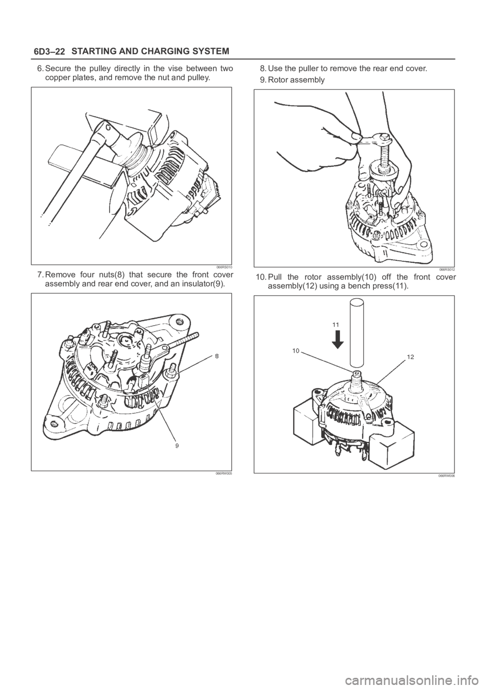
6. Secure the pulley directly in the vise between two
copper plates, and remove the nut and pulley.
066RS010
7. Remove four nuts(8) that secure the front cover
assembly and rear end cover, and an insulator(9).
066RW005
8. Use the puller to remove the rear end cover.
9. Rotor assembly
066RS012
10. Pull the rotor assembly(10) off the front cover
assembly(12) using a bench press(11).
066RW006
Page 1116 of 6000
6D3–25 STARTING AND CHARGING SYSTEM
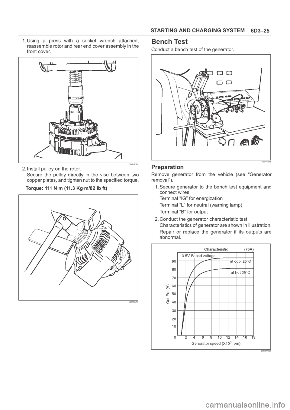
1. Using a press with a socket wrench attached,
reassemble rotor and rear end cover assembly in the
front cover.
066RS022
2. Install pulley on the rotor.
Secure the pulley directly in the vise between two
copper plates, and tighten nut to the specified torque.
Torque: 111 Nꞏm (11.3 Kgꞏm/82 lb ft)
066RS010
Bench Test
Conduct a bench test of the generator.
066RS023
Preparation
Remove generator from the vehicle (see “Generator
removal”).
1. Secure generator to the bench test equipment and
connect wires.
Terminal “IG” for energization
Terminal “L” for neutral (warning lamp)
Terminal “B” for output
2. Conduct the generator characteristic test.
Characteristics of generator are shown in illustration.
Repair or replace the generator if its outputs are
abnormal.
B06RW001
Page 1118 of 6000
6E–1 ENGINE DRIVEABILITY AND EMISSIONS
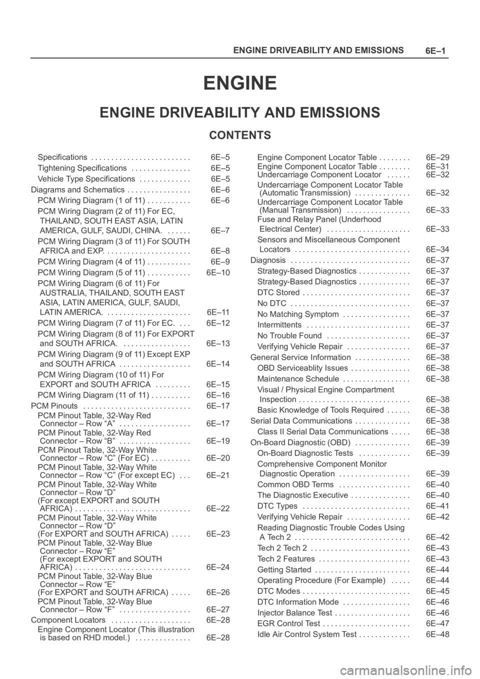
ENGINE
ENGINE DRIVEABILITY AND EMISSIONS
CONTENTS
Specifications 6E–5. . . . . . . . . . . . . . . . . . . . . . . . .
Tightening Specifications 6E–5. . . . . . . . . . . . . . .
Vehicle Type Specifications 6E–5. . . . . . . . . . . . .
Diagrams and Schematics 6E–6. . . . . . . . . . . . . . . .
PCM Wiring Diagram (1 of 11) 6E–6. . . . . . . . . . .
PCM Wiring Diagram (2 of 11) For EC,
THAILAND, SOUTH EAST ASIA, LATIN
AMERICA, GULF, SAUDI, CHINA. 6E–7. . . . . .
PCM Wiring Diagram (3 of 11) For SOUTH
AFRICA and EXP. 6E–8. . . . . . . . . . . . . . . . . . . . .
PCM Wiring Diagram (4 of 11) 6E–9. . . . . . . . . . .
PCM Wiring Diagram (5 of 11) 6E–10. . . . . . . . . . .
PCM Wiring Diagram (6 of 11) For
AUSTRALIA, THAILAND, SOUTH EAST
ASIA, LATIN AMERICA, GULF, SAUDI,
LATIN AMERICA. 6E–11. . . . . . . . . . . . . . . . . . . . .
PCM Wiring Diagram (7 of 11) For EC. 6E–12. . .
PCM Wiring Diagram (8 of 11) For EXPORT
and SOUTH AFRICA. 6E–13. . . . . . . . . . . . . . . . .
PCM Wiring Diagram (9 of 11) Except EXP
and SOUTH AFRICA 6E–14. . . . . . . . . . . . . . . . . .
PCM Wiring Diagram (10 of 11) For
EXPORT and SOUTH AFRICA 6E–15. . . . . . . . .
PCM Wiring Diagram (11 of 11) 6E–16. . . . . . . . . .
PCM Pinouts 6E–17. . . . . . . . . . . . . . . . . . . . . . . . . . .
PCM Pinout Table, 32-Way Red
Connector – Row “A” 6E–17. . . . . . . . . . . . . . . . . .
PCM Pinout Table, 32-Way Red
Connector – Row “B” 6E–19. . . . . . . . . . . . . . . . . .
PCM Pinout Table, 32-Way White
Connector – Row “C” (For EC) 6E–20. . . . . . . . . .
PCM Pinout Table, 32-Way White
Connector – Row “C” (For except EC) 6E–21. . .
PCM Pinout Table, 32-Way White
Connector – Row “D”
(For except EXPORT and SOUTH
AFRICA) 6E–22. . . . . . . . . . . . . . . . . . . . . . . . . . . . .
PCM Pinout Table, 32-Way White
Connector – Row “D”
(For EXPORT and SOUTH AFRICA) 6E–23. . . . .
PCM Pinout Table, 32-Way Blue
Connector – Row “E”
(For except EXPORT and SOUTH
AFRICA) 6E–24. . . . . . . . . . . . . . . . . . . . . . . . . . . . .
PCM Pinout Table, 32-Way Blue
Connector – Row “E”
(For EXPORT and SOUTH AFRICA) 6E–26. . . . .
PCM Pinout Table, 32-Way Blue
Connector – Row “F” 6E–27. . . . . . . . . . . . . . . . . .
Component Locators 6E–28. . . . . . . . . . . . . . . . . . . .
Engine Component Locator (This illustration
is based on RHD model.) 6E–28. . . . . . . . . . . . . . Engine Component Locator Table 6E–29. . . . . . . .
Engine Component Locator Table 6E–31. . . . . . . .
Undercarriage Component Locator 6E–32. . . . . .
Undercarriage Component Locator Table
(Automatic Transmission) 6E–32. . . . . . . . . . . . . .
Undercarriage Component Locator Table
(Manual Transmission) 6E–33. . . . . . . . . . . . . . . .
Fuse and Relay Panel (Underhood
Electrical Center) 6E–33. . . . . . . . . . . . . . . . . . . . .
Sensors and Miscellaneous Component
Locators 6E–34. . . . . . . . . . . . . . . . . . . . . . . . . . . . .
Diagnosis 6E–37. . . . . . . . . . . . . . . . . . . . . . . . . . . . . .
Strategy-Based Diagnostics 6E–37. . . . . . . . . . . . .
Strategy-Based Diagnostics 6E–37. . . . . . . . . . . . .
DTC Stored 6E–37
. . . . . . . . . . . . . . . . . . . . . . . . . . .
No DTC 6E–37. . . . . . . . . . . . . . . . . . . . . . . . . . . . . .
No Matching Symptom 6E–37. . . . . . . . . . . . . . . . .
Intermittents 6E–37. . . . . . . . . . . . . . . . . . . . . . . . . .
No Trouble Found 6E–37. . . . . . . . . . . . . . . . . . . . .
Verifying Vehicle Repair 6E–37. . . . . . . . . . . . . . . .
General Service Information 6E–38. . . . . . . . . . . . . .
OBD Serviceablity Issues 6E–38. . . . . . . . . . . . . . .
Maintenance Schedule 6E–38. . . . . . . . . . . . . . . . .
Visual / Physical Engine Compartment
Inspection 6E–38. . . . . . . . . . . . . . . . . . . . . . . . . . . .
Basic Knowledge of Tools Required 6E–38. . . . . .
Serial Data Communications 6E–38. . . . . . . . . . . . . .
Class II Serial Data Communications 6E–38. . . . .
On-Board Diagnostic (OBD) 6E–39. . . . . . . . . . . . . .
On-Board Diagnostic Tests 6E–39. . . . . . . . . . . . .
Comprehensive Component Monitor
Diagnostic Operation 6E–39. . . . . . . . . . . . . . . . . .
Common OBD Terms 6E–40. . . . . . . . . . . . . . . . . .
The Diagnostic Executive 6E–40. . . . . . . . . . . . . . .
DTC Types 6E–41. . . . . . . . . . . . . . . . . . . . . . . . . . .
Verifying Vehicle Repair 6E–42. . . . . . . . . . . . . . . .
Reading Diagnostic Trouble Codes Using
A Tech 2 6E–42. . . . . . . . . . . . . . . . . . . . . . . . . . . . .
Tech 2 Tech 2 6E–43. . . . . . . . . . . . . . . . . . . . . . . . .
Tech 2 Features 6E–43. . . . . . . . . . . . . . . . . . . . . . .
Getting Started 6E–44. . . . . . . . . . . . . . . . . . . . . . . .
Operating Procedure (For Example) 6E–44. . . . .
DTC Modes 6E–45. . . . . . . . . . . . . . . . . . . . . . . . . . .
DTC Information Mode 6E–46. . . . . . . . . . . . . . . . .
Injector Balance Test 6E–46. . . . . . . . . . . . . . . . . . .
EGR Control Test 6E–47. . . . . . . . . . . . . . . . . . . . . .
Idle Air Control System Test 6E–48. . . . . . . . . . . . .
Page 1136 of 6000
6E–19 ENGINE DRIVEABILITY AND EMISSIONS
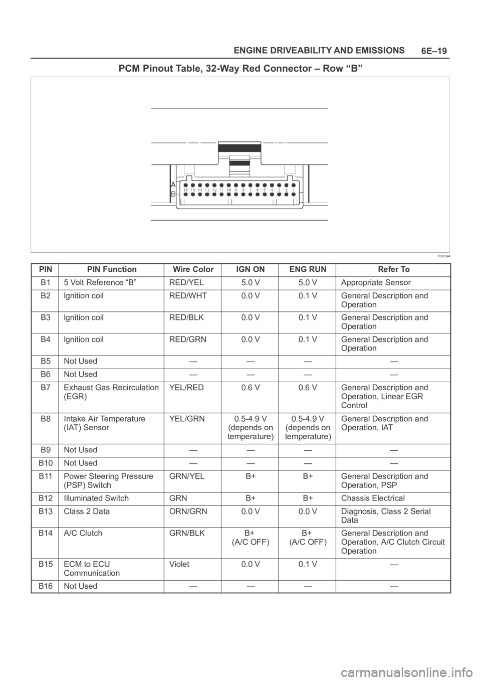
PCM Pinout Table, 32-Way Red Connector – Row “B”
TS23344
PINPIN FunctionWire ColorIGN ONENG RUNRefer To
B15 Volt Reference “B”RED/YEL5.0 V5.0 VAppropriate Sensor
B2lgnition coilRED/WHT0.0 V0.1 VGeneral Description and
Operation
B3lgnition coilRED/BLK0.0 V0.1 VGeneral Description and
Operation
B4lgnition coilRED/GRN0.0 V0.1 VGeneral Description and
Operation
B5Not Used————
B6Not Used————
B7Exhaust Gas Recirculation
(EGR)YEL/RED0.6 V0.6 VGeneral Description and
Operation, Linear EGR
Control
B8Intake Air Temperature
(IAT) SensorYEL/GRN0.5-4.9 V
(depends on
temperature)0.5-4.9 V
(depends on
temperature)General Description and
Operation, IAT
B9Not Used————
B10Not Used————
B11Power Steering Pressure
(PSP) SwitchGRN/YELB+B+General Description and
Operation, PSP
B12Illuminated SwitchGRNB+B+Chassis Electrical
B13Class 2 DataORN/GRN0.0 V0.0 VDiagnosis, Class 2 Serial
Data
B14A/C ClutchGRN/BLKB+
(A/C OFF)B+
(A/C OFF)General Description and
Operation, A/C Clutch Circuit
Operation
B15ECM to ECU
CommunicationViolet0.0 V0.1 V—
B16Not Used————
Page 1156 of 6000
6E–39 ENGINE DRIVEABILITY AND EMISSIONS
The data displayed on the other Tech 2 will appear the
same, with some exceptions. Some Tech 2s will only be
able to display certain vehicle parameters as values that
are a coded representation of the true or actual value. For
more information on this system of coding, refer to
Decimal/Binary/Hexadecimal Conversions. On this
vehicle Tech 2 displays the actual values for vehicle
parameters. It will not be necessary to perform any
conversions from coded values to actual values.
On-Board Diagnostic (OBD)
On-Board Diagnostic Tests
A diagnostic test is a series of steps, the result of which is
a pass or fail reported to the diagnostic executive. When
a diagnostic test reports a pass result, the diagnostic
executive records the following data:
The diagnostic test has been completed since the last
ignition cycle.
The diagnostic test has passed during the current
ignition cycle.
The fault identified by the diagnostic test is not
currently active.
W h e n a d i a g n o s t i c t e s t r e p o r t s a fail result, the diagnostic
executive records the following data:
The diagnostic test has been completed since the last
ignition cycle.
The fault identified by the diagnostic test is currently
active.
The fault has been active during this ignition cycle.
The operating conditions at the time of the failure.
Remember, a fuel trim DTC may be triggered by a list of
vehicle faults. Make use of all information available (other
DTCs stored, rich or lean condition, etc.) when
diagnosing a fuel trim fault.
Comprehensive Component Monitor
Diagnostic Operation
Input Components:
Input components are monitored for circuit continuity and
out-of-range values. This includes rationality checking.
Rationality checking refers to indicating a fault when the
signal from a sensor does not seem reasonable, i.e.
Throttle Position (TP) sensor that indicates high throttle
position at low engine loads or MAP voltage. Input
components may include, but are not limited to the
following sensors:
Vehicle Speed Sensor (VSS)
Crankshaft Position (CKP) sensor
Knock Sensor (KS)
Throttle Position (TP) sensor
Engine Coolant Temperature (ECT) sensor
Camshaft Position (CMP) sensor
Manifold Absolute Pressure (MAP) sensor
Mass Air Flow (MAF) sensorIn addition to the circuit continuity and rationality check,
the ECT sensor is monitored for its ability to achieve a
steady state temperature to enable closed loop fuel
control.
Output Components:
Output components are diagnosed for proper response to
control module commands. Components where
functional monitoring is not feasible will be monitored for
circuit continuity and out-of-range values if applicable.
Output components to be monitored include, but are not
limited to, the following circuits:
Idle Air Control (IAC) Motor
Electronic Transmission controls
A/C relays
Cooling fan relay
VSS output
MIL control
Cruise control inhibit
Refer to PCM and Sensors in General Descriptions.
Passive and Active Diagnostic Tests
A passive test is a diagnostic test which simply monitors a
vehicle system or component. Conversely, an active test,
actually takes some sort of action when performing
diagnostic functions, often in response to a failed passive
test. For example, the EGR diagnostic active test will
force the EGR valve open during closed throttle decel
and/or force the EGR valve closed during a steady state.
Either action should result in a change in manifold
pressure.
Intrusive Diagnostic Tests
This is any on-board test run by the Diagnostic
Management System which may have an effect on
vehicle performance or emission levels.
Warm-Up Cycle
A warm-up cycle means that engine at temperature must
reach a minimum of 70
C (160F) and rise at least 22C
(40
F) over the course of a trip.
Freeze Frame
Freeze Frame is an element of the Diagnostic
Management System which stores various vehicle
information at the moment an emissions-related fault is
stored in memory and when the MIL is commanded on.
These data can help to identify the cause of a fault. Refer
to
Storing And Erasing Freeze Fame Data for more
detailed information.
Failure Records
Failure Records data is an enhancement of the OBD
Freeze Frame feature. Failure Records store the same
vehicle information as does Freeze Frame, but it will store
that information for any fault which is stored in on-board
memory, while Freeze Frame stores information only for
emission-related faults that command the MIL on.
Page 1157 of 6000
6E–40
ENGINE DRIVEABILITY AND EMISSIONS
Common OBD Terms
Diagnostic
When used as a noun, the word diagnostic refers to any
on-board test run by the vehicle’s Diagnostic
Management System. A diagnostic is simply a test run on
a system or component to determine if the system or
component is operating according to specification. There
are many diagnostics, shown in the following list:
Oxygen sensors
Oxygen sensor heaters
EGR
Catalyst monitoring
Enable Criteria
The term “enable criteria” is engineering language for the
conditions necessary for a given diagnostic test to run.
Each diagnostic has a specific list of conditions which
must be met before the diagnostic will run. “Enable
criteria” is another way of saying “conditions required”.
The enable criteria for each diagnostic is listed on the first
page of the DTC description under the heading
“Conditions for Setting the DTC”. Enable criteria varies
with each diagnostic, and typically includes, but is not
limited to the following items:
engine speed
vehicle speed
ECT
MAF/MAP
barometric pressure
IAT
TP
fuel trim
TCC enabled
A/C on
Tr i p
Technically, a trip is a key on-run-key off cycle in which all
the enable criteria for a given diagnostic are met, allowing
the diagnostic to run. Unfortunately, this concept is not
quite that simple. A trip is official when all the enable
criteria for a given diagnostic are met. But because the
enable criteria vary from one diagnostic to another, the
definition of trip varies as well. Some diagnostic are run
when the vehicle is at operating temperature, some when
the vehicle first start up; some require that the vehicle be
cruising at a steady highway speed, some run only when
the vehicle is idle; some diagnostics function with the
TCC disables. Some run only immediately following a
cold engine start-up.
A trip then, is defined as a key on-run-key off cycle in
which the vehicle was operated in such a way as to satisfy
the enables criteria for a given diagnostic, and this
diagnostic will consider this cycle to be one trip. However,
another diagnostic with a different set of enable criteria
(which were not met) during this driving event, would not
consider it a trip. No trip will occur for that particular
diagnostic until the vehicle is driven in such a way as to
meet all the enable criteria.
The Diagnostic Executive
The Diagnostic Executive is a unique segment of
software which is designed to coordinate and prioritize
the diagnostic procedures as well as define the protocol
for recording and displaying their results. The main
responsibilities of the Diagnostic Executive are listed as
following:
Commanding the MIL (“Check Engine” lamp) on and
off
DTC logging and clearing
Freeze Frame data for the first emission related DTC
recorded
Non-emission related Service Lamp (future)
Operating conditions Failure Records buffer, (the
number of records will vary)
Current status information on each diagnostic
The Diagnostic Executive records DTCs and turns on the
MIL when emission-related faults occur. It can also turn
off the MIL if the conditions cease which caused the DTC
to set.
Diagnostic Information
The diagnostic charts and functional checks are designed
to locate a faulty circuit or component through a process
of logical decisions. The charts are prepared with the
requirement that the vehicle functioned correctly at the
time of assembly and that there are not multiple faults
present.
There is a continuous self-diagnosis on certain control
functions. This diagnostic capability is complemented by
the diagnostic procedures contained in this manual. The
language of communicating the source of the malfunction
is a system of diagnostic trouble codes. When a
malfunction is detected by the control module, a
diagnostic trouble code is set and the Malfunction
Indicator Lamp (MIL) (“Check Engine” lamp) is
illuminated.
Malfunction Indicator Lamp (MIL)
The Malfunction Indicator Lamp (MIL) looks the same as
the MIL you are already familiar with (“Check Engine”
lamp). However, OBD requires that the it illuminate under
a strict set of guide lines.
Basically, the MIL is turned on when the PCM detects a
DTC that will impact the vehicle emissions.
The MIL is under the control of the Diagnostic Executive.
The MIL will be turned on if an emissions-related
diagnostic test indicates a malfunction has occurred. It
will stay on until the system or component passes the
same test, for three consecutive trips, with no
emissionsrelated faults.
Extinguishing the MIL
When the MIL is on, the Diagnostic Executive will turn off
the MIL after
three consecutive trips that a “test passed”
has been reported for the diagnostic test that originally
caused the MIL to illuminate.
Although the MIL has been turned off, the DTC will remain
in the PCM memory (both Freeze Frame and Failure
Records) until
forty(40) warm-up cycles after no faults
have been completed.