ESP OPEL FRONTERA 1998 Repair Manual
[x] Cancel search | Manufacturer: OPEL, Model Year: 1998, Model line: FRONTERA, Model: OPEL FRONTERA 1998Pages: 6000, PDF Size: 97 MB
Page 1775 of 6000

6A – 42 ENGINE MECHANICAL
2. Cylinder head for cracks, especially between valve
seats and in the exhaust ports.
3. Cylinder head deck for corrosion, sand particles in
head and porosity.
CAUTION: Do not attempt to weld the cylinder
head. Replace it.
4. Cylinder head lower surface for flatness.
Use a straight edge and a feeler gauge to measure
the cylinder head lower surface warpage.
If the measured values exceed the specified limit,
the cylinder head must be replaced.
Cylinder Head Lower Face Warpage:
Standard: 0.075 mm (0.0029 in) or less
Limit: 0.2 mm (0.0079 in)
Cylinder Head Height:
Standard: 95 mm (3.740 in)
5. Water jacket sealing plugs seating surfaces.
6. Use a straight edge and a feeler gauge to measure
the manifold cylinder head fitting face warpage.
If the measured values exceed the specified limit,
the manifold must be replaced.
Exhaust Manifold Warpage:
Standard: 0.05 mm (0.0020 in) or less
Limit: 0.20 mm (0.0079 in)
CAUTION: Do not attempt to weld the cylinder
head. Replace it.
REASSEMBLY
1. Cylinder Head
Refer to “Cylinder Head Gasket”.
2. Glow Plug and Glow Plug Connector
Tighten glow plugs.
Torque: 15 Nꞏm (1.5 kgꞏm/11 lb ft)
011RW006
012RW053
Page 1919 of 6000
6E–26
4JX1–TC ENGINE DRIVEABILITY AND EMISSIONS
Output Components:
Output components are diagnosed for proper response to
control module commands. Components where
functional monitoring is not feasible will be monitored for
circuit continuity and out-of-range values if applicable.
Output components to be monitored include, but are not
limited to, the following circuit:
EGR VSV
EGR EVRV
Electronic Transmission controls
Injector
Intake throttle
Glow plug
MIL control
Refer to ECM and Sensors in General Descriptions.
Passive and Active Diagnostic Tests
A passive test is a diagnostic test which simply monitors a
vehicle system or component. Conversely, an active test,
actually takes some sort of action when performing
diagnostic functions, often in response to a failed passive
test.
Intrusive Diagnostic Tests
This is any on-board test run by the Diagnostic
Management System which may have an effect on
vehicle performance or emission levels.
Warm-Up Cycle
A warm-up cycle means that engine at temperature must
reach a minimum of 70
C (160F) and rise at least 22C
(40
F) over the course of a trip.
Freeze Frame
Freeze Frame is an element of the Diagnostic
Management System which stores various vehicle
information at the moment an emissions-related fault is
stored in memory and when the MIL is commanded on.
These data can help to identify the cause of a fault. Refer
to
Storing And Erasing Freeze Fame Data for more
detailed information.
Failure Records
Failure Records data is an enhancement of the OBD
Freeze Frame feature. Failure Records store the same
vehicle information as does Freeze Frame, but it will store
that information for any fault which is stored in on-board
memory, while Freeze Frame stores information only for
emission-related faults that command the MIL on.
Common OBD Terms
Diagnostic
When used as a noun, the word diagnostic refers to any
on-board test run by the vehicle’s Diagnostic
Management System. A diagnostic is simply a test run on
a system or component to determine if the system or
component is operating according to specification. There
are many diagnostics, shown in the following list:
EGR
engine speed
vehicle speed
ECT
MAP
VSV
IAT
ITP
AP
FT (Fuel Temp)
RP (Rail Pressure)
OT (Oil Temp)
EGR EVRV
Idle SW
Brake SW
The Diagnostic Executive
The Diagnostic Executive is a unique segment of
software which is designed to coordinate and prioritize
the diagnostic procedures as well as define the protocol
for recording and displaying their results. The main
responsibilities of the Diagnostic Executive are listed as
follows:
Commanding the MIL (“Check Engine” lamp) on and
off
DTC logging and clearing
Freeze Frame data for the first emission related DTC
recorded
Current status information on each diagnostic
Diagnostic Information
The diagnostic charts and functional checks are designed
to locate a faulty circuit or component through a process
of logical decisions. The charts are prepared with the
requirement that the vehicle functioned correctly at the
time of assembly and that there are not multiple faults
present.
There is a continuous self-diagnosis on certain control
functions. This diagnostic capability is complemented by
the diagnostic procedures contained in this manual. The
language of communicating the source of the malfunction
is a system of diagnostic trouble codes. When a
malfunction is detected by the control module, a
diagnostic trouble code is set and the Malfunction
Indicator Lamp (MIL) (“Check Engine” lamp) is
illuminated.
Malfunction Indicator Lamp (MIL)
The Malfunction Indicator Lamp (MIL) looks the same as
the MIL you are already familiar with “Check Engine”
lamp.
Basically, the MIL is turned on when the ECM detects a
DTC that will impact the vehicle emissions.
When the MIL remains “ON” while the engine is
running, or when a malfunction is suspected due to a
driveability or emissions problem, a Powertrain
On-Board Diagnostic (OBD) System Check must be
performed. The procedures for these checks are
given in On-Board Diagnostic (OBD) System Check.
These checks will expose faults which may not be
detected if other diagnostics are performed first.
DTC Types
Characteristic of Code
Page 1920 of 6000
6E–27 4JX1–TC ENGINE DRIVEABILITY AND EMISSIONS
Non-Emissions related
Dose not request illumination of any lamp
Stores a History DTC on the first trip with a fail
Stores Fail Record when test fails
Updates the Fail Record each time the diagnostic test
fails
Storing and Erasing Freeze Frame Data and Failure
Records
The data captured is called Freeze Frame data. The
Freeze Frame data is very similar to a single record of
operating conditions. Whenever the MIL is illuminated,
the corresponding record of operating conditions is
recorded to the Freeze Frame buffer.
Data from these faults take precedence over data
associated with any other fault. The Freeze Frame data
will not be erased unless the associated history DTC is
cleared.
Each time a diagnostic test reports a failure, the current
engine operating conditions are recorded in the
Failure
Records
buffer. A subsequent failure will update the
recorded operating conditions. The following operating
conditions for the diagnostic test which failed
typically
include the following parameters:
Engine Speed
Engine Load
Engine Coolant Temperature
Vehicle Speed
Intake Throttle Position
MAP
Injector Base Pulse Width
Loop Status
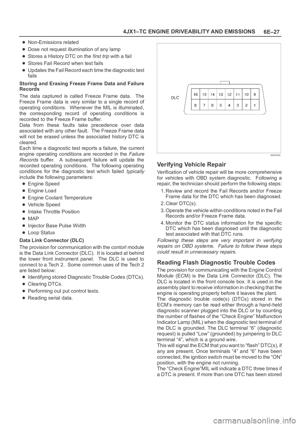
Data Link Connector (DLC)
The provision for communication with the contorl module
is the Data Link Connector (DLC). It is located at behind
the lower front instrument panel. The DLC is used to
connect to a Tech 2. Some common uses of the Tech 2
are listed below:
Identifying stored Diagnostic Trouble Codes (DTCs).
Clearing DTCs.
Performing out put control tests.
Reading serial data.
060RW046
Verifying Vehicle Repair
Verification of vehicle repair will be more comprehensive
for vehicles with OBD system diagnostic. Following a
repair, the technician should perform the following steps:
1. Review and record the Fail Records and/or Freeze
Frame data for the DTC which has been diagnosed.
2. Clear DTC(s).
3. Operate the vehicle within conditions noted in the Fail
Records and/or Freeze Frame data.
4. Monitor the DTC status information for the specific
DTC which has been diagnosed until the diagnostic
test associated with that DTC runs.
Following these steps are very important in verifying
repairs on OBD systems. Failure to follow these steps
could result in unnecessary repairs.
Reading Flash Diagnostic Trouble Codes
The provision for communicating with the Engine Control
Module (ECM) is the Data Link Connector (DLC). The
DLC is located in the front console box. It is used in the
assembly plant to receive information in checking that the
engine is operating properly before it leaves the plant.
The diagnostic trouble code(s) (DTCs) stored in the
ECM’s memory can be read either through a hand-held
diagnostic scanner plugged into the DLC or by counting
the number of flashes of the “Check Engine” Malfunction
Indicator Lamp (MIL) when the diagnostic test terminal of
the DLC is grounded. The DLC terminal “6” (diagnostic
request) is pulled “Low” (grounded) by jumpering to DLC
terminal “4”, which is a ground wire.
This will signal the ECM that you want to “flash” DTC(s), if
any are present. Once terminals “4” and “6” have been
connected, the ignition switch must be moved to the “ON”
position, with the engine not running.
The “Check Engine”MIL will indicate a DTC three times if
a DTC is present. If more than one DTC has been stored
Page 1949 of 6000
6E–56
4JX1–TC ENGINE DRIVEABILITY AND EMISSIONS
Diagnostic Trouble Code (DTC) P0107 (Flash DTC 34)
MAP Sensor Circuit Low Voltage
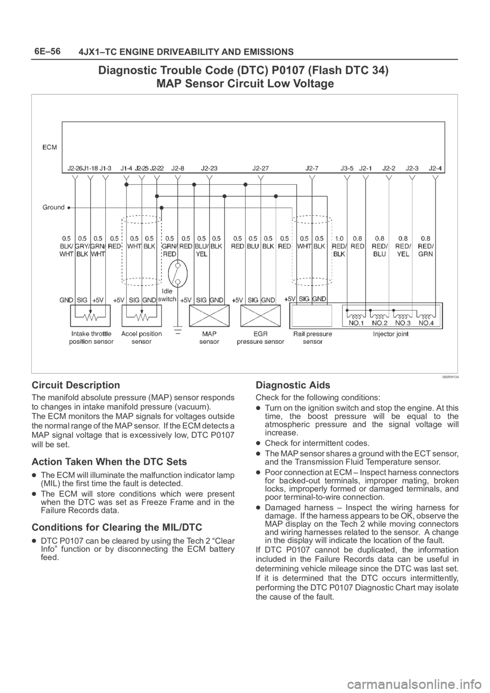
060RW134
Circuit Description
The manifold absolute pressure (MAP) sensor responds
to changes in intake manifold pressure (vacuum).
The ECM monitors the MAP signals for voltages outside
the normal range of the MAP sensor. If the ECM detects a
MAP signal voltage that is excessively low, DTC P0107
will be set.
Action Taken When the DTC Sets
The ECM will illuminate the malfunction indicator lamp
(MIL) the first time the fault is detected.
The ECM will store conditions which were present
when the DTC was set as Freeze Frame and in the
Failure Records data.
Conditions for Clearing the MIL/DTC
DTC P0107 can be cleared by using the Tech 2 “Clear
Info” function or by disconnecting the ECM battery
feed.
Diagnostic Aids
Check for the following conditions:
Turn on the ignition switch and stop the engine. At this
time, the boost pressure will be equal to the
atmospheric pressure and the signal voltage will
increase.
Check for intermittent codes.
The MAP sensor shares a ground with the ECT sensor,
and the Transmission Fluid Temperature sensor.
Poor connection at ECM – Inspect harness connectors
for backed-out terminals, improper mating, broken
locks, improperly formed or damaged terminals, and
poor terminal-to-wire connection.
Damaged harness – Inspect the wiring harness for
damage. If the harness appears to be OK, observe the
MAP display on the Tech 2 while moving connectors
and wiring harnesses related to the sensor. A change
in the display will indicate the location of the fault.
If DTC P0107 cannot be duplicated, the information
included in the Failure Records data can be useful in
determining vehicle mileage since the DTC was last set.
If it is determined that the DTC occurs intermittently,
performing the DTC P0107 Diagnostic Chart may isolate
the cause of the fault.
Page 1951 of 6000
6E–58
4JX1–TC ENGINE DRIVEABILITY AND EMISSIONS
Diagnostic Trouble Code (DTC) P0108 (Flash DTC 34)
MAP Sensor Circuit High Voltage
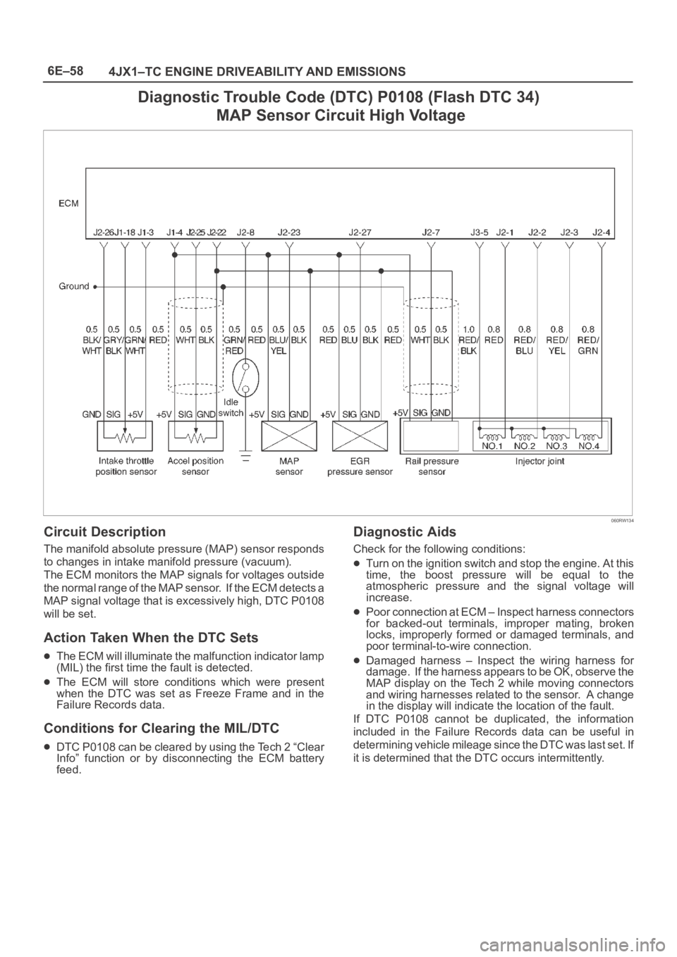
060RW134
Circuit Description
The manifold absolute pressure (MAP) sensor responds
to changes in intake manifold pressure (vacuum).
The ECM monitors the MAP signals for voltages outside
the normal range of the MAP sensor. If the ECM detects a
MAP signal voltage that is excessively high, DTC P0108
will be set.
Action Taken When the DTC Sets
The ECM will illuminate the malfunction indicator lamp
(MIL) the first time the fault is detected.
The ECM will store conditions which were present
when the DTC was set as Freeze Frame and in the
Failure Records data.
Conditions for Clearing the MIL/DTC
DTC P0108 can be cleared by using the Tech 2 “Clear
Info” function or by disconnecting the ECM battery
feed.
Diagnostic Aids
Check for the following conditions:
Turn on the ignition switch and stop the engine. At this
time, the boost pressure will be equal to the
atmospheric pressure and the signal voltage will
increase.
Poor connection at ECM – Inspect harness connectors
for backed-out terminals, improper mating, broken
locks, improperly formed or damaged terminals, and
poor terminal-to-wire connection.
Damaged harness – Inspect the wiring harness for
damage. If the harness appears to be OK, observe the
MAP display on the Tech 2 while moving connectors
and wiring harnesses related to the sensor. A change
in the display will indicate the location of the fault.
If DTC P0108 cannot be duplicated, the information
included in the Failure Records data can be useful in
determining vehicle mileage since the DTC was last set. If
it is determined that the DTC occurs intermittently.
Page 1975 of 6000

6E–82
4JX1–TC ENGINE DRIVEABILITY AND EMISSIONS
Diagnostic Trouble Code (DTC) P0192 (Flash DTC 63)
Rail Pressure Sensor Low Voltage
060RW135
Circuit Description
The rail pressure (RP) sensor responds to changes in oil
manifold pressure.
The ECM monitors the RP signals for voltages outside the
normal range of the RP sensor. If the ECM detects a RP
signal voltage that is excessively low, DTC P0192 will be
set.
Action Taken When the DTC Sets
The ECM will store conditions which were present
when the DTC was set as Freeze Frame and in the
Failure Records data.
Conditions for Clearing the MIL/DTC
DTC P0192 can be cleared by using the Tech 2 “Clear
Info” function or by disconnecting the ECM battery
feed.
Diagnostic Aids
Check for the following conditions:
Poor connection at ECM – Inspect harness connectors
for backed-out terminals, improper mating, broken
locks, improperly formed or damaged terminals, and
poor terminal-to-wire connection.
Damaged harness – Inspect the wiring harness for
damage. If the harness appears to be OK, observe the
RP display on the Tech 2 while moving connectors and
wiring harnesses related to the sensor. A change in the
display will indicate the location of the fault.
If DTC P0192 cannot be duplicated, the information
included in the Failure Records data can be useful in
determining vehicle mileage since the DTC was last set.
If it is determined that the DTC occurs intermittently,
performing the DTC P0192 Diagnostic Chart may isolate
the cause of the fault.
Page 1977 of 6000

6E–84
4JX1–TC ENGINE DRIVEABILITY AND EMISSIONS
Diagnostic Trouble Code (DTC) P0193 (Flash DTC 63)
Rail Pressure Sensor High Voltage
060RW135
Circuit Description
The rail pressure (RP) sensor responds to changes in oil
manifold pressure.
The ECM monitors the RP signals for voltages outside the
normal range of the RP sensor. If the ECM detects a RP
signal voltage that is excessively high, DTC P0193 will be
set.
Action Taken When the DTC Sets
The ECM will store conditions which were present
when the DTC was set as Freeze Frame and in the
Failure Records data.
Conditions for Clearing the MIL/DTC
DTC P0193 can be cleared by using the Tech 2 “Clear
Info” function or by disconnecting the ECM battery
feed.
Diagnostic Aids
Check for the following conditions:
Poor connection at ECM – Inspect harness connectors
for backed-out terminals, improper mating, broken
locks, improperly formed or damaged terminals, and
poor terminal-to-wire connection.
Damaged harness – Inspect the wiring harness for
damage. If the harness appears to be OK, observe the
RP display on the Tech 2 while moving connectors and
wiring harnesses related to the sensor. A change in the
display will indicate the location of the fault.
If DTC P0193 cannot be duplicated, the information
included in the Failure Records data can be useful in
determining vehicle mileage since the DTC was last set. If
it is determined that the DTC occurs intermittently,
performing the DTC P0193 Diagnostic Chart may isolate
the cause of the fault.
Page 1981 of 6000

6E–88
4JX1–TC ENGINE DRIVEABILITY AND EMISSIONS
Diagnostic Trouble Code (DTC) P1194 (Flash DTC 61)
Rail Pressure System Low Voltage
060RW134
Circuit Description
The rail pressure (RP) sensor responds to changes in oil
rail pressure.
The ECM monitors the RP signals for voltages outside the
normal range of the RP sensor. If the ECM detects a RP
signal voltage that is excessively low, DTC P1194 will be
set.
Action Taken When the DTC Sets
The ECM will store conditions which were present
when the DTC was set as Freeze Frame and in the
Failure Records data.
Conditions for Clearing the MIL/DTC
DTC P1194 can be cleared by using the Tech 2 “Clear
Info” function or by disconnecting the ECM battery
feed.
Diagnostic Aids
Check for the following conditions:
Check for intermittent codes.
Poor connection at ECM – Inspect harness connectors
for backed-out terminals, improper mating, broken
locks, improperly formed or damaged terminals, and
poor terminal-to-wire connection.
Damaged harness – Inspect the wiring harness for
damage. If the harness appears to be OK, observe the
MAP display on the Tech 2 while moving connectors
and wiring harnesses related to the sensor. A change
in the display will indicate the location of the fault.
If DTC P1194 cannot be duplicated, the information
included in the Failure Records data can be useful in
determining vehicle mileage since the DTC was last set.
If it is determined that the DTC occurs intermittently,
performing the DTC P1194 Diagnostic Chart may isolate
the cause of the fault.
Page 1983 of 6000
6E–90
4JX1–TC ENGINE DRIVEABILITY AND EMISSIONS
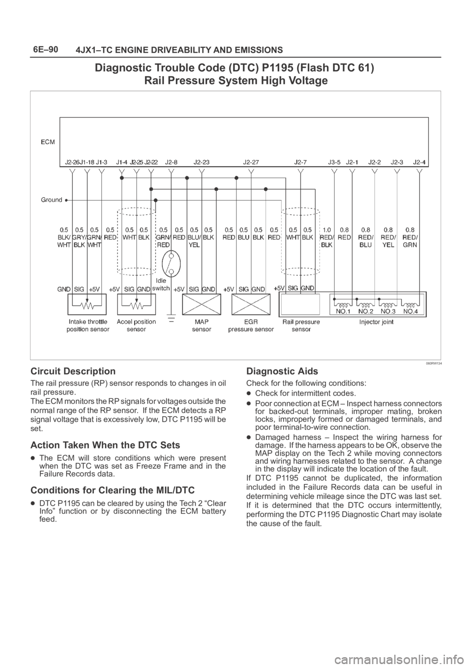
Diagnostic Trouble Code (DTC) P1195 (Flash DTC 61)
Rail Pressure System High Voltage
060RW134
Circuit Description
The rail pressure (RP) sensor responds to changes in oil
rail pressure.
The ECM monitors the RP signals for voltages outside the
normal range of the RP sensor. If the ECM detects a RP
signal voltage that is excessively low, DTC P1195 will be
set.
Action Taken When the DTC Sets
The ECM will store conditions which were present
when the DTC was set as Freeze Frame and in the
Failure Records data.
Conditions for Clearing the MIL/DTC
DTC P1195 can be cleared by using the Tech 2 “Clear
Info” function or by disconnecting the ECM battery
feed.
Diagnostic Aids
Check for the following conditions:
Check for intermittent codes.
Poor connection at ECM – Inspect harness connectors
for backed-out terminals, improper mating, broken
locks, improperly formed or damaged terminals, and
poor terminal-to-wire connection.
Damaged harness – Inspect the wiring harness for
damage. If the harness appears to be OK, observe the
MAP display on the Tech 2 while moving connectors
and wiring harnesses related to the sensor. A change
in the display will indicate the location of the fault.
If DTC P1195 cannot be duplicated, the information
included in the Failure Records data can be useful in
determining vehicle mileage since the DTC was last set.
If it is determined that the DTC occurs intermittently,
performing the DTC P1195 Diagnostic Chart may isolate
the cause of the fault.
Page 2004 of 6000

6E–111 4JX1–TC ENGINE DRIVEABILITY AND EMISSIONS
Diagnostic Trouble Code (DTC) P0219 (Flash DTC 11)
Engine Over Speed Warning
060RW133
Circuit Description
The CKP reference signal is produced by the crankshaft
position (CKP) sensor. During one crankshaft revolution,
CKP crankshaft reference pulses will be produced. The
Engine Control Module ECM uses the CKP reference
signal to calculate engine RPM and crankshaft position.
Action Taken When the DTC Sets
The ECM will store conditions which were present
when the DTC was set as Freeze Frame and in the
Failure Records data.
Conditions for Clearing the MIL/DTC
DTC P0219 can be cleared by using the Tech 2 “Clear
Info” function or by disconnecting the ECM battery
feed.
Diagnostic Aids
Check for:
Poor connection – Inspect the CKP harness and
connectors for improper mating, broken locks,
improperly formed or damaged terminals, and poor
terminal-to-wire connection.
Damaged X57 – Inspect the X57 for damage.
DTC P0219 – Engine Over Speed Warning
StepActionVa l u e ( s )Ye sNo
1Was the “On-Board Diagnostic (OBD) System Check”
performed?
—Go to Step 2
Go to OBD
System
Check
2Check the responsibility.
Was the driver responsibility?
—Go to Step 3Go to Chart 4