ignition OPEL FRONTERA 1998 Workshop Manual
[x] Cancel search | Manufacturer: OPEL, Model Year: 1998, Model line: FRONTERA, Model: OPEL FRONTERA 1998Pages: 6000, PDF Size: 97 MB
Page 4941 of 6000
6E–284
ENGINE DRIVEABILITY AND EMISSIONS
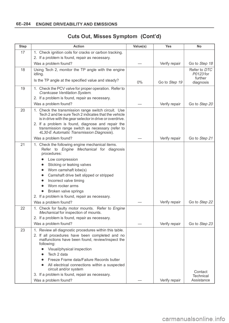
Cuts Out, Misses Symptom
StepNo Ye s Va l u e ( s ) Action
171. Check ignition coils for cracks or carbon tracking.
2. If a problem is found, repair as necessary.
Was a problem found?
—Verify repairGo to Step 18
18Using Tech 2, monitor the TP angle with the engine
idling.
Is the TP angle at the specified value and steady?
0%Go to Step 19
Refer to DTC
P0123
for
further
diagnosis
191. Check the PCV valve for proper operation. Refer to
Crankcase Ventilation System.
2. If a problem is found, repair as necessary.
Was a problem found?
—Verify repairGo to Step 20
201. Check the transmission range switch circuit. Use
Tech 2 and be sure Tech 2 indicates that the vehicle
is in drive with the gear selector in drive or overdrive.
2. If a problem is found, diagnose and repair the
transmission range switch as necessary (refer to
4L30-E Automatic Transmission Diagnosis).
Was a problem found?
—Verify repairGo to Step 21
211. Check the following engine mechanical items.
Refer to
Engine Mechanical for diagnosis
procedures:
Low compression
Sticking or leaking valves
Worn camshaft lobe(s)
Camshaft drive belt slipped or stripped
Incorrect valve timing
Worn rocker arms
Broken valve springs
2. If a problem is found, repair as necessary.
Was a problem found?
—Verify repairGo to Step 22
221. Check for faulty motor mounts. Refer to Engine
Mechanical
for inspection of mounts.
2. If a problem is found, repair as necessary.
Was a problem found?
—Verify repairGo to Step 23
231. Review all diagnostic procedures within this table.
2. If all procedures have been completed and no
malfunctions have been found, review/inspect the
following:
Visual/physical inspection
Te c h 2 d a t a
Freeze Frame data/Failure Records butter
All electrical connections within a suspected
circuit and/or system
3. If a problem is found, repair as necessary.
Was a problem found?
—Verify repair
Contact
Te c h n i c a l
Assistance
Page 4943 of 6000
6E–286
ENGINE DRIVEABILITY AND EMISSIONS
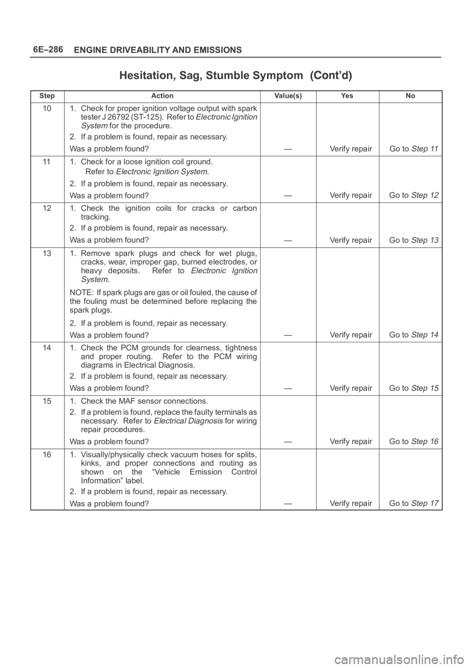
Hesitation, Sag, Stumble Symptom
StepNo Ye s Va l u e ( s ) Action
101. Check for proper ignition voltage output with spark
tester J 26792 (ST-125). Refer to
Electronic Ignition
System
for the procedure.
2. If a problem is found, repair as necessary.
Was a problem found?
—Verify repairGo to Step 11
111. Check for a loose ignition coil ground.
Refer to
Electronic Ignition System.
2. If a problem is found, repair as necessary.
Was a problem found?
—Verify repairGo to Step 12
121. Check the ignition coils for cracks or carbon
tracking.
2. If a problem is found, repair as necessary.
Was a problem found?
—Verify repairGo to Step 13
131. Remove spark plugs and check for wet plugs,
cracks, wear, improper gap, burned electrodes, or
heavy deposits. Refer to
Electronic Ignition
System
.
NOTE: If spark plugs are gas or oil fouled, the cause of
the fouling must be determined before replacing the
spark plugs.
2. If a problem is found, repair as necessary.
Was a problem found?
—Verify repairGo to Step 14
141. Check the PCM grounds for clearness, tightness
and proper routing. Refer to the PCM wiring
diagrams in Electrical Diagnosis.
2. If a problem is found, repair as necessary.
Was a problem found?
—Verify repairGo to Step 15
151. Check the MAF sensor connections.
2. If a problem is found, replace the faulty terminals as
necessary. Refer to
Electrical Diagnosis for wiring
repair procedures.
Was a problem found?
—Verify repairGo to Step 16
161. Visually/physically check vacuum hoses for splits,
kinks, and proper connections and routing as
shown on the “Vehicle Emission Control
Information” label.
2. If a problem is found, repair as necessary.
Was a problem found?
—Verify repairGo to Step 17
Page 4945 of 6000
6E–288
ENGINE DRIVEABILITY AND EMISSIONS
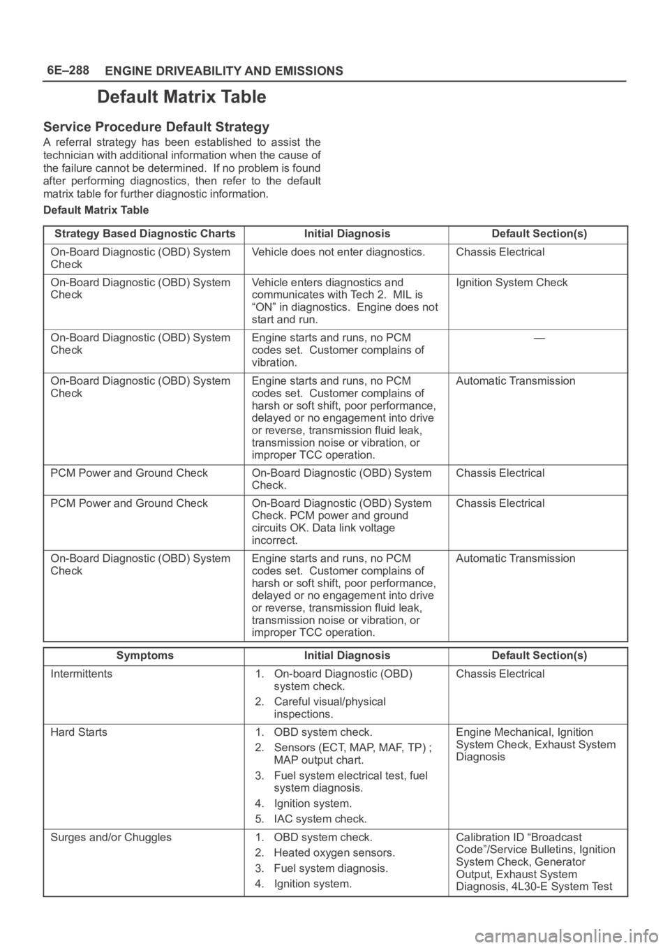
Default Matrix Table
Service Procedure Default Strategy
A referral strategy has been established to assist the
technician with additional information when the cause of
the failure cannot be determined. If no problem is found
after performing diagnostics, then refer to the default
matrix table for further diagnostic information.
Default Matrix Table
Strategy Based Diagnostic Charts
Initial DiagnosisDefault Section(s)
On-Board Diagnostic (OBD) System
CheckVehicle does not enter diagnostics.Chassis Electrical
On-Board Diagnostic (OBD) System
CheckVehicle enters diagnostics and
communicates with Tech 2. MIL is
“ON” in diagnostics. Engine does not
start and run.Ignition System Check
On-Board Diagnostic (OBD) System
CheckEngine starts and runs, no PCM
codes set. Customer complains of
vibration.—
On-Board Diagnostic (OBD) System
CheckEngine starts and runs, no PCM
codes set. Customer complains of
harsh or soft shift, poor performance,
delayed or no engagement into drive
or reverse, transmission fluid leak,
transmission noise or vibration, or
improper TCC operation.Automatic Transmission
PCM Power and Ground CheckOn-Board Diagnostic (OBD) System
Check.Chassis Electrical
PCM Power and Ground CheckOn-Board Diagnostic (OBD) System
Check. PCM power and ground
circuits OK. Data link voltage
incorrect.Chassis Electrical
On-Board Diagnostic (OBD) System
CheckEngine starts and runs, no PCM
codes set. Customer complains of
harsh or soft shift, poor performance,
delayed or no engagement into drive
or reverse, transmission fluid leak,
transmission noise or vibration, or
improper TCC operation.Automatic Transmission
SymptomsInitial DiagnosisDefault Section(s)
Intermittents1. On-board Diagnostic (OBD)
system check.
2. Careful visual/physical
inspections.Chassis Electrical
Hard Starts1. OBD system check.
2. Sensors (ECT, MAP, MAF, TP) ;
MAP output chart.
3. Fuel system electrical test, fuel
system diagnosis.
4. Ignition system.
5. IAC system check.Engine Mechanical, Ignition
System Check, Exhaust System
Diagnosis
Surges and/or Chuggles1. OBD system check.
2. Heated oxygen sensors.
3. Fuel system diagnosis.
4. Ignition system.Calibration ID “Broadcast
Code”/Service Bulletins, Ignition
System Check, Generator
Output, Exhaust System
Diagnosis, 4L30-E System Test
Page 4946 of 6000
6E–289 ENGINE DRIVEABILITY AND EMISSIONS
Symptoms Default Section(s)Initial Diagnosis
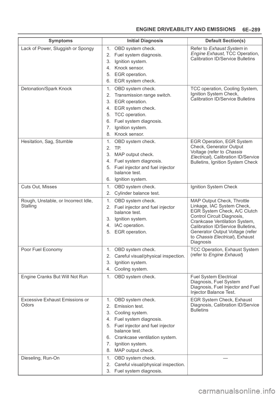
Lack of Power, Sluggish or Spongy1. OBD system check.
2. Fuel system diagnosis.
3. Ignition system.
4. Knock sensor.
5. EGR operation.
6. EGR system check.Refer to Exhaust System in
Engine Exhaust, TCC Operation,
Calibration ID/Service Bulletins
Detonation/Spark Knock1. OBD system check.
2. Transmission range switch.
3. EGR operation.
4. EGR system check.
5. TCC operation.
6. Fuel system diagnosis.
7. Ignition system.
8. Knock sensor.TCC operation, Cooling System,
Ignition System Check,
Calibration ID/Service Bulletins
Hesitation, Sag, Stumble1. OBD system check.
2. TP.
3. MAP output check.
4. Fuel system diagnosis.
5. Fuel injector and fuel injector
balance test.
6. Ignition system.EGR Operation, EGR System
Check, Generator Output
Voltage (refer to
Chassis
Electrical
), Calibration ID/Service
Bulletins, Ignition System Check
Cuts Out, Misses1. OBD system check.
2. Cylinder balance test.Ignition System Check
Rough, Unstable, or Incorrect Idle,
Stalling1. OBD system check.
2. Fuel injector and fuel injector
balance test.
3. Ignition system.
4. IAC operation.
5. EGR operation.MAP Output Check, Throttle
Linkage, IAC System Check,
EGR System Check, A/C Clutch
Control Circuit Diagnosis,
Crankcase Ventilation System,
Calibration ID/Service Bulletins,
Generator Output Voltage (refer
to
Chassis Electrical), Exhaust
Diagnosis
Poor Fuel Economy1. OBD system check.
2. Careful visual/physical inspection.
3. Ignition system.
4. Cooling system.TCC Operation, Exhaust System
(refer to
Engine Exhaust)
Engine Cranks But Will Not Run1. OBD system check.Fuel System Electrical
Diagnosis, Fuel System
Diagnosis, Fuel Injector and Fuel
Injector Balance Test.
Excessive Exhaust Emissions or
Odors1. OBD system check.
2. Emission test.
3. Cooling system.
4. Fuel system diagnosis.
5. Fuel injector and fuel injector
balance test.
6. Crankcase ventilation system.
7. Ignition system.
8. MAP output check.EGR System Check, Exhaust
Diagnosis, Calibration ID/Service
Bulletins
Dieseling, Run-On1. OBD system check.
2. Careful visual/physical inspection.
3. Fuel system diagnosis.—
Page 4947 of 6000
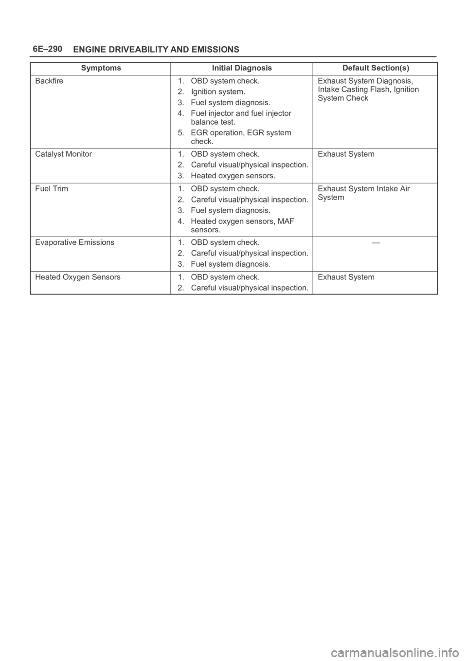
6E–290
ENGINE DRIVEABILITY AND EMISSIONS
Symptoms Default Section(s)Initial Diagnosis
Backfire1. OBD system check.
2. Ignition system.
3. Fuel system diagnosis.
4. Fuel injector and fuel injector
balance test.
5. EGR operation, EGR system
check.Exhaust System Diagnosis,
Intake Casting Flash, Ignition
System Check
Catalyst Monitor1. OBD system check.
2. Careful visual/physical inspection.
3. Heated oxygen sensors.Exhaust System
Fuel Trim1. OBD system check.
2. Careful visual/physical inspection.
3. Fuel system diagnosis.
4. Heated oxygen sensors, MAF
sensors.Exhaust System Intake Air
System
Evaporative Emissions1. OBD system check.
2. Careful visual/physical inspection.
3. Fuel system diagnosis.—
Heated Oxygen Sensors1. OBD system check.
2. Careful visual/physical inspection.Exhaust System
Page 4956 of 6000
6E–299 ENGINE DRIVEABILITY AND EMISSIONS
damage, therefore, it is important to use care when
handling and testing electronic components.
NOTE: To prevent possible Electrostatic Discharge
damage, follow these guidelines:
Do not touch the control module connector pins or
soldered components on the control module circuit
board.
Do not open the replacement part package until the
part is ready to be installed.
Before removing the part from the package, ground
the package to a known good ground on the vehicle.
If the part has been handled while sliding across the
seat, or while sitting down from a standing position, or
while walking a distance, touch a known good ground
before installing the part.
NOTE: To prevent internal PCM damage, the ignition
must be in the “OFF” position in order to disconnect or
reconnect power to the PCM (for example: battery cable,
PCM pigtail, PCM fuse, jumper cables, etc.).
IMPORTANT:When replacing the production PCM
with a service PCM, it is important to transfer the
broadcast code and production PCM number to the
service PCM label. This will allow positive identification of
PCM parts throughout the service life of the vehicle. Do
not record this information on the metal PCM cover.
IMPORTANT:The ignition should always be in the
“OFF” position in order to install or remove the PCM
connectors.
Service of the PCM should normally consist of either re-
placement of the PCM or EEPROM programming. If the
diagnostic procedures call for the PCM to be replaced,
the PCM should be checked first to ensure it is the correct
part. If it is, remove the faulty PCM and install the new
service PCM.
The service PCM EEPROM will not be programmed.
DTC P0601 indicates the check sum error.
Removal Procedure
1. Disconnect the negative battery cable.
2. Block the wheels.
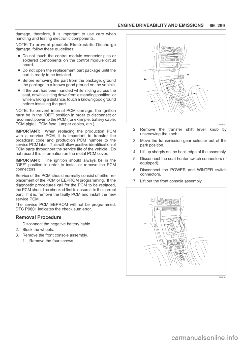
3. Remove the front console assembly.
1. Remove the four screws.
TS23755
2. Remove the transfer shift lever knob by
unscrewing the knob.
3. Move the transmission gear selector out of the
park position.
4. Lift up sharply on the back edge of the assembly.
5. Disconnect the seat heater switch connectors (if
equipped).
6. Disconnect the POWER and WINTER switch
connectors.
7. Lift out the front console assembly.
TS23756
Page 4957 of 6000
6E–300
ENGINE DRIVEABILITY AND EMISSIONS
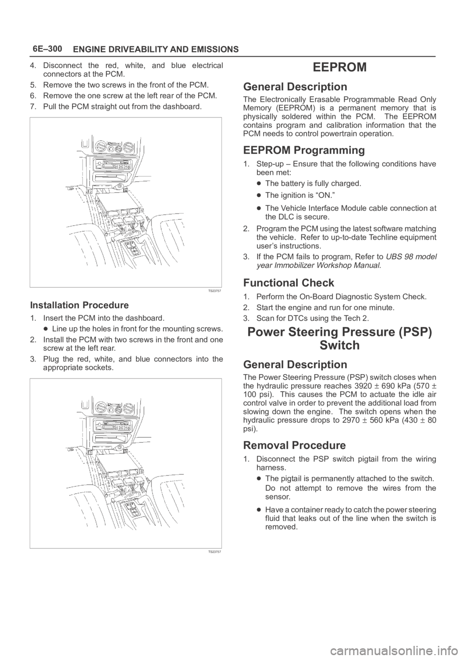
4. Disconnect the red, white, and blue electrical
connectors at the PCM.
5. Remove the two screws in the front of the PCM.
6. Remove the one screw at the left rear of the PCM.
7. Pull the PCM straight out from the dashboard.
TS23757
Installation Procedure
1. Insert the PCM into the dashboard.
Line up the holes in front for the mounting screws.
2. Install the PCM with two screws in the front and one
screw at the left rear.
3. Plug the red, white, and blue connectors into the
appropriate sockets.
TS23757
EEPROM
General Description
The Electronically Erasable Programmable Read Only
Memory (EEPROM) is a permanent memory that is
physically soldered within the PCM. The EEPROM
contains program and calibration information that the
PCM needs to control powertrain operation.
EEPROM Programming
1. Step-up – Ensure that the following conditions have
been met:
The battery is fully charged.
The ignition is “ON.”
The Vehicle Interface Module cable connection at
the DLC is secure.
2. Program the PCM using the latest software matching
the vehicle. Refer to up-to-date Techline equipment
user’s instructions.
3. If the PCM fails to program, Refer to
UBS 98 model
year Immobilizer Workshop Manual.
Functional Check
1. Perform the On-Board Diagnostic System Check.
2. Start the engine and run for one minute.
3. Scan for DTCs using the Tech 2.
Power Steering Pressure (PSP)
Switch
General Description
The Power Steering Pressure (PSP) switch closes when
the hydraulic pressure reaches 3920
690 kPa (570
100 psi). This causes the PCM to actuate the idle air
control valve in order to prevent the additional load from
slowing down the engine. The switch opens when the
hydraulic pressure drops to 2970
560 kPa (430 80
psi).
Removal Procedure
1. Disconnect the PSP switch pigtail from the wiring
harness.
The pigtail is permanently attached to the switch.
Do not attempt to remove the wires from the
sensor.
Have a container ready to catch the power steering
fluid that leaks out of the line when the switch is
removed.
Page 4981 of 6000
6E–324
ENGINE DRIVEABILITY AND EMISSIONS
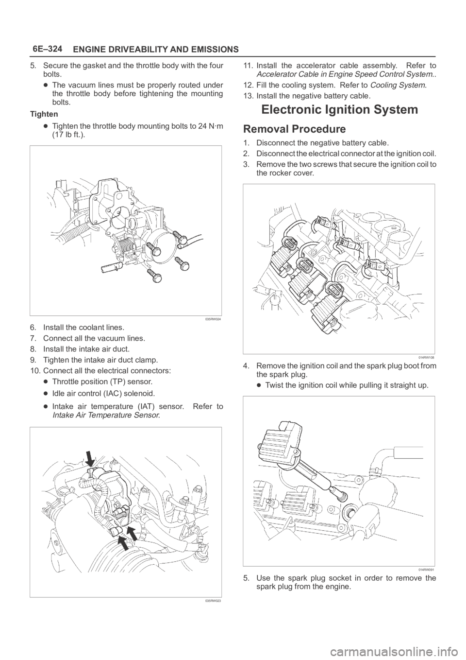
5. Secure the gasket and the throttle body with the four
bolts.
The vacuum lines must be properly routed under
the throttle body before tightening the mounting
bolts.
Tighten
Tighten the throttle body mounting bolts to 24 Nꞏm
(17 lb ft.).
035RW024
6. Install the coolant lines.
7. Connect all the vacuum lines.
8. Install the intake air duct.
9. Tighten the intake air duct clamp.
10. Connect all the electrical connectors:
Throttle position (TP) sensor.
Idle air control (IAC) solenoid.
Intake air temperature (IAT) sensor. Refer to
Intake Air Temperature Sensor.
035RW023
11. Install the accelerator cable assembly. Refer to
Accelerator Cable in Engine Speed Control System..
12. Fill the cooling system. Refer to
Cooling System.
13. Install the negative battery cable.
Electronic Ignition System
Removal Procedure
1. Disconnect the negative battery cable.
2. Disconnect the electrical connector at the ignition coil.
3. Remove the two screws that secure the ignition coil to
the rocker cover.
014RW108
4. Remove the ignition coil and the spark plug boot from
the spark plug.
Twist the ignition coil while pulling it straight up.
014RW091
5. Use the spark plug socket in order to remove the
spark plug from the engine.
Page 4982 of 6000
6E–325 ENGINE DRIVEABILITY AND EMISSIONS
Spark Plug Gap Check
Check the gap of all spark plugs before installation.
Use a round wire feeler gauge to ensure an accurate
check.
Plugs installed with the wrong gap can cause poor
engine performance and excessive emissions.
Installation Procedure
NOTE: The plug must thread smoothly into the cylinder
head and be fully seated. Use a thread chaser if
necessary to clean the threads in the cylinder head.
Cross-threading or failure to fully seat the spark plug can
cause plug overheating, exhaust blow-by gas, or thread
damage. Do not overtighten the spark plugs. Over
tightening can cause aluminum threads to strip.
1. Install the spark plug in the engine. Use the
appropriate spark plug socket.
Tighten
Tighten the spark plug to 18 Nꞏm (13 lb ft.).
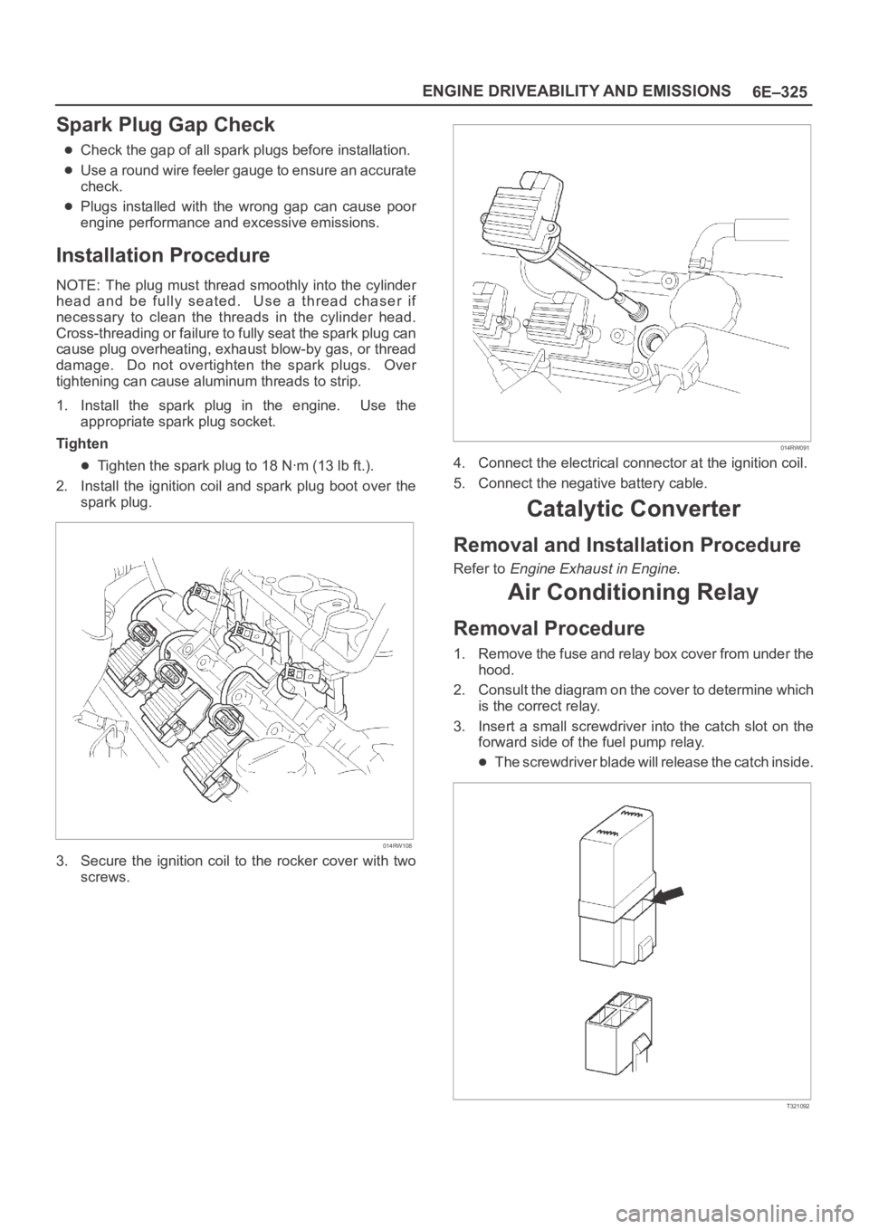
2. Install the ignition coil and spark plug boot over the
spark plug.
014RW108
3. Secure the ignition coil to the rocker cover with two
screws.
014RW091
4. Connect the electrical connector at the ignition coil.
5. Connect the negative battery cable.
Catalytic Converter
Removal and Installation Procedure
Refer to Engine Exhaust in Engine.
Air Conditioning Relay
Removal Procedure
1. Remove the fuse and relay box cover from under the
hood.
2. Consult the diagram on the cover to determine which
is the correct relay.
3. Insert a small screwdriver into the catch slot on the
forward side of the fuel pump relay.
The screwdriver blade will release the catch inside.
T321092
Page 4992 of 6000
6E–335 ENGINE DRIVEABILITY AND EMISSIONS
General Description
General Description (PCM and
Sensors)
58X Reference PCM Input
The powertrain control module (PCM) uses this signal
from the crankshaft position (CKP) sensor to calculate
engine RPM and crankshaft position at all engine speeds.
The PCM also uses the pulses on this circuit to initiate
injector pulses. If the PCM receives no pulses on this
circuit, DTC P0337 will set. The engine will not start and
run without using the 58X reference signal.
A/C Request Signal
This signal tells the PCM when the A/C mode is selected
at the A/C control head. The PCM uses this to adjust the
idle speed before turning “ON” the A/C clutch. The A/C
compressor will be inoperative if this signal is not
available to the PCM.
Refer to
A/C Clutch Circuit Diagnosis for A/C wiring
diagrams and diagnosis for the A/C electrical system.
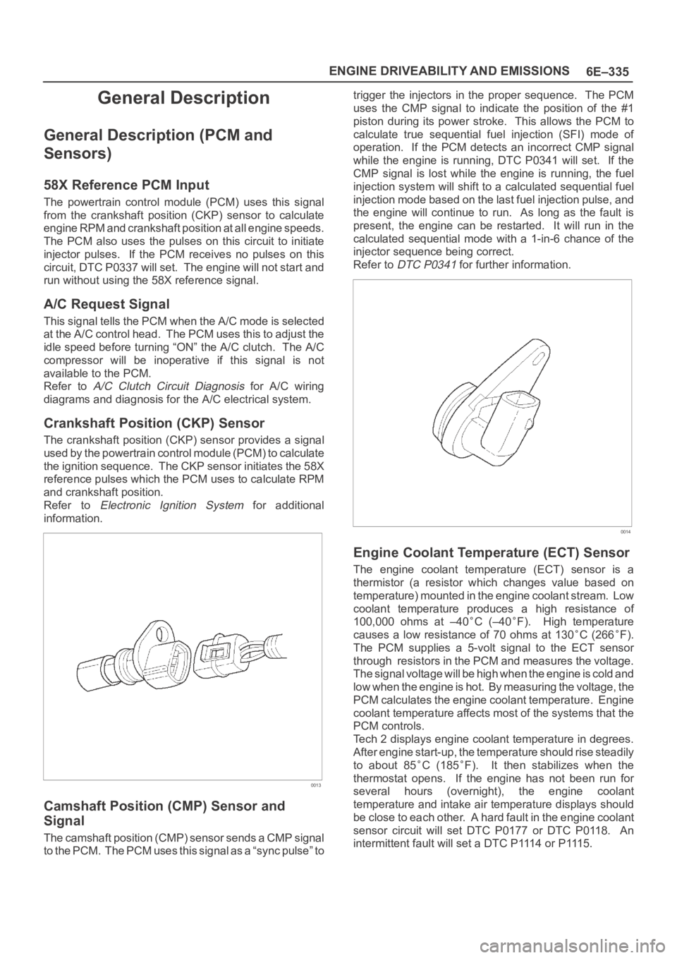
Crankshaft Position (CKP) Sensor
The crankshaft position (CKP) sensor provides a signal
used by the powertrain control module (PCM) to calculate
the ignition sequence. The CKP sensor initiates the 58X
reference pulses which the PCM uses to calculate RPM
and crankshaft position.
Refer to
Electronic Ignition System for additional
information.
0013
Camshaft Position (CMP) Sensor and
Signal
The camshaft position (CMP) sensor sends a CMP signal
t o t h e P C M . T h e P C M u s e s t h i s s i g n a l a s a “ s y n c p u l s e ” t otrigger the injectors in the proper sequence. The PCM
uses the CMP signal to indicate the position of the #1
piston during its power stroke. This allows the PCM to
calculate true sequential fuel injection (SFI) mode of
operation. If the PCM detects an incorrect CMP signal
while the engine is running, DTC P0341 will set. If the
CMP signal is lost while the engine is running, the fuel
injection system will shift to a calculated sequential fuel
injection mode based on the last fuel injection pulse, and
the engine will continue to run. As long as the fault is
present, the engine can be restarted. It will run in the
calculated sequential mode with a 1-in-6 chance of the
injector sequence being correct.
Refer to
DTC P0341 for further information.
0014
Engine Coolant Temperature (ECT) Sensor
The engine coolant temperature (ECT) sensor is a
thermistor (a resistor which changes value based on
temperature) mounted in the engine coolant stream. Low
coolant temperature produces a high resistance of
100,000 ohms at –40
C (–40F). High temperature
causes a low resistance of 70 ohms at 130
C (266F).
The PCM supplies a 5-volt signal to the ECT sensor
through resistors in the PCM and measures the voltage.
The signal voltage will be high when the engine is cold and
low when the engine is hot. By measuring the voltage, the
PCM calculates the engine coolant temperature. Engine
coolant temperature affects most of the systems that the
PCM controls.
Tech 2 displays engine coolant temperature in degrees.
After engine start-up, the temperature should rise steadily
to about 85
C (185F). It then stabilizes when the
thermostat opens. If the engine has not been run for
several hours (overnight), the engine coolant
temperature and intake air temperature displays should
be close to each other. A hard fault in the engine coolant
sensor circuit will set DTC P0177 or DTC P0118. An
intermittent fault will set a DTC P1114 or P1115.