ignition OPEL FRONTERA 1998 Workshop Manual
[x] Cancel search | Manufacturer: OPEL, Model Year: 1998, Model line: FRONTERA, Model: OPEL FRONTERA 1998Pages: 6000, PDF Size: 97 MB
Page 5004 of 6000
6E–347 ENGINE DRIVEABILITY AND EMISSIONS
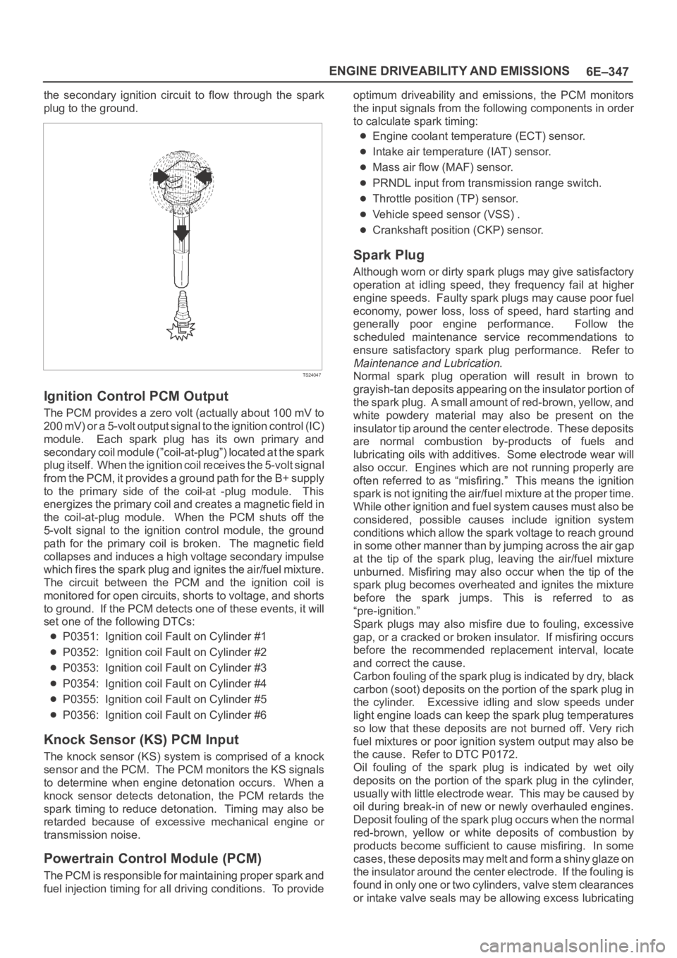
the secondary ignition circuit to flow through the spark
plug to the ground.
TS24047
Ignition Control PCM Output
The PCM provides a zero volt (actually about 100 mV to
200 mV) or a 5-volt output signal to the ignition control (IC)
module. Each spark plug has its own primary and
secondary coil module (”coil-at-plug”) located at the spark
plug itself. When the ignition coil receives the 5-volt signal
from the PCM, it provides a ground path for the B+ supply
to the primary side of the coil-at -plug module. This
energizes the primary coil and creates a magnetic field in
the coil-at-plug module. When the PCM shuts off the
5-volt signal to the ignition control module, the ground
path for the primary coil is broken. The magnetic field
collapses and induces a high voltage secondary impulse
which fires the spark plug and ignites the air/fuel mixture.
The circuit between the PCM and the ignition coil is
monitored for open circuits, shorts to voltage, and shorts
to ground. If the PCM detects one of these events, it will
set one of the following DTCs:
P0351: Ignition coil Fault on Cylinder #1
P0352: Ignition coil Fault on Cylinder #2
P0353: Ignition coil Fault on Cylinder #3
P0354: Ignition coil Fault on Cylinder #4
P0355: Ignition coil Fault on Cylinder #5
P0356: Ignition coil Fault on Cylinder #6
Knock Sensor (KS) PCM Input
The knock sensor (KS) system is comprised of a knock
sensor and the PCM. The PCM monitors the KS signals
to determine when engine detonation occurs. When a
knock sensor detects detonation, the PCM retards the
spark timing to reduce detonation. Timing may also be
retarded because of excessive mechanical engine or
transmission noise.
Powertrain Control Module (PCM)
The PCM is responsible for maintaining proper spark and
fuel injection timing for all driving conditions. To provideoptimum driveability and emissions, the PCM monitors
the input signals from the following components in order
to calculate spark timing:
Engine coolant temperature (ECT) sensor.
Intake air temperature (IAT) sensor.
Mass air flow (MAF) sensor.
PRNDL input from transmission range switch.
Throttle position (TP) sensor.
Vehicle speed sensor (VSS) .
Crankshaft position (CKP) sensor.
Spark Plug
Although worn or dirty spark plugs may give satisfactory
operation at idling speed, they frequency fail at higher
engine speeds. Faulty spark plugs may cause poor fuel
economy, power loss, loss of speed, hard starting and
generally poor engine performance. Follow the
scheduled maintenance service recommendations to
ensure satisfactory spark plug performance. Refer to
Maintenance and Lubrication.
Normal spark plug operation will result in brown to
grayish-tan deposits appearing on the insulator portion of
the spark plug. A small amount of red-brown, yellow, and
white powdery material may also be present on the
insulator tip around the center electrode. These deposits
are normal combustion by-products of fuels and
lubricating oils with additives. Some electrode wear will
also occur. Engines which are not running properly are
often referred to as “misfiring.” This means the ignition
spark is not igniting the air/fuel mixture at the proper time.
While other ignition and fuel system causes must also be
considered, possible causes include ignition system
conditions which allow the spark voltage to reach ground
in some other manner than by jumping across the air gap
at the tip of the spark plug, leaving the air/fuel mixture
unburned. Misfiring may also occur when the tip of the
spark plug becomes overheated and ignites the mixture
before the spark jumps. This is referred to as
“pre-ignition.”
Spark plugs may also misfire due to fouling, excessive
gap, or a cracked or broken insulator. If misfiring occurs
before the recommended replacement interval, locate
and correct the cause.
Carbon fouling of the spark plug is indicated by dry, black
carbon (soot) deposits on the portion of the spark plug in
the cylinder. Excessive idling and slow speeds under
light engine loads can keep the spark plug temperatures
so low that these deposits are not burned off. Very rich
fuel mixtures or poor ignition system output may also be
the cause. Refer to DTC P0172.
Oil fouling of the spark plug is indicated by wet oily
deposits on the portion of the spark plug in the cylinder,
usually with little electrode wear. This may be caused by
oil during break-in of new or newly overhauled engines.
Deposit fouling of the spark plug occurs when the normal
red-brown, yellow or white deposits of combustion by
products become sufficient to cause misfiring. In some
c a s e s , t h e s e d e p o s i t s m a y m e l t a n d f o r m a s h i n y g l a z e o n
the insulator around the center electrode. If the fouling is
found in only one or two cylinders, valve stem clearances
or intake valve seals may be allowing excess lubricating
Page 5406 of 6000

ENGINE ELECTRICAL 6D – 3
ON-VEHICLE SERVICE
BATTERY CHARGING
Observe the following safety precautions when
charging the battery:
1. Never attempt to charge the battery when the fluid
level is below the lower level line on the side of the
battery. In this case, the battery must be replaced.
2. Pay close attention to the battery during the
charging procedure.
Battery charging should be discontinued or the rate
of charge reduced if the battery feels hot to the
touch.
Battery charging should be discontinued or the rate
of charge reduced if the battery begins to gas or
spew electrolyte from the vent holes.
3. In order to more easily view the hydrometer blue
dot or ring, it may be necessary to jiggle or tilt the
battery.
4. Battery temperature can have a great effect on
battery charging capacity.
5. The sealed battery used on this vehicle may be
either quick-charged or slow-charged in the same
manner as other batteries.
Whichever method you decide to use, be sure that
you completely charge the battery. Never partially
charge the battery.
JUMP STARTING
JUMP STARTING WITH AN AUXILIARY
(BOOSTER) BATTERY
CAUTION: Never push or tow the vehicle in an
attempt to start it. Serious damage to the emission
system as well as other vehicle parts will result.
Treat both the discharged battery and the booster
battery with great care when using jumper cables.
Carefully follow the jump starting procedure, being
careful at all times to avoid sparking.
WARNING: Failure to carefully follow the jump
starting procedure could result in the following:
1. Serious personal injury, particularly to your
eyes.
2. Property damage from a battery explosion,
battery acid, or an electrical fire.
3. Damage to the electronic components of one or
both vehicles.
Never expose the battery to an open flame or electrical
spark. Gas generated by the battery may catch fire or
explode. Remove any rings, watches, or other jewelry
before working around the battery. Protect your eyes by
wearing an approved set of goggles.
Never allow battery fluid to come in contact with your
eyes or skin.
Never allow battery fluid to come in contact with fabrics
or painted surfaces.
Battery fluid is a highly corrosive acid.Should battery fluid come in contact with your eyes,
skin, fabric, or a painted surface, immediately and
thoroughly rinse the affected area with clean tap water.
Never allow metal tools or jumper cables to come in
contact with the positive battery terminal, or any other
metal surface of the vehicle. This will protect against a
short circuit.
Always keep batteries out of the reach of young
children.
JUMP STARTING PROCEDURE
1. Set the vehicle parking brake.
If the vehicle is equipped with an automatic
transmission, place the selector lever in the “PARK”
position.
If the vehicle is equipped with a manual
transmission place the shift lever in the “NEUTRAL”
position.
Turn “OFF” the ignition.
Turn “OFF” all lights and any other accessory
requiring electrical power.
2. Look at the built-in hydrometer.
If the indication area of the built-in hydrometer is
completely clear, do not try to jump start.
3. Attach the end of one jumper cable to the positive
terminal of the booster battery.
Attach the other end of the same cable to the
positive terminal of the discharged battery.
Do not allow the vehicles to touch each other.
This will cause a ground connection, effectively
neutralizing the charging procedure.
Be sure that the booster battery has a 12 volt rating.
4. Attach one end of the remaining cable to the
negative terminal of the booster battery.
Attach the other end of the same cable to a solid
engine ground (such as the A/C compressor
bracket or the generator mounting bracket) of the
vehicle with the discharged battery.
This ground connection must be at least 450 mm
(18 in) from the battery of the vehicle whose battery
is being charged.
WARNING: Never attach the end of the jumper
cable directly to the negative terminal of the dead
battery.
5. Start the engine of the vehicle with the good battery.
Make sure that all unnecessary electrical
accessories have been turned “OFF”.
6. Start the engine of the vehicle with the dead battery.
7. To remove the jumper cables, follow the above
directions in the reverse order.
Be sure to first disconnect the negative cable from
the vehicle with the discharged battery.
Page 5447 of 6000
6E–18
4JX1–TC ENGINE DRIVEABILITY AND EMISSIONS
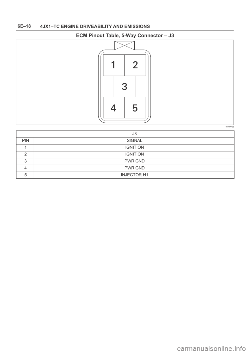
ECM Pinout Table, 5-Way Connector – J3
060RW139
J3
PINSIGNAL
1IGNITION
2IGNITION
3PWR GND
4PWR GND
5INJECTOR H1
Page 5452 of 6000
6E–23 4JX1–TC ENGINE DRIVEABILITY AND EMISSIONS
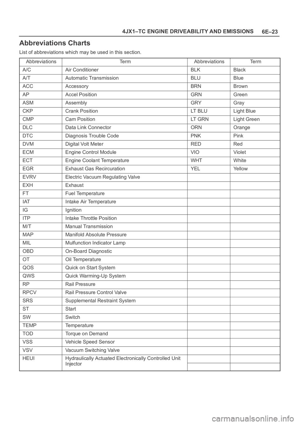
Abbreviations Charts
List of abbreviations which may be used in this section.
Abbreviations
Te r mAbbreviationsTe r m
A/CAir ConditionerBLKBlack
A/TAutomatic TransmissionBLUBlue
ACCAccessoryBRNBrown
APAccel PositionGRNGreen
ASMAssemblyGRYGray
CKPCrank PositionLT B L ULight Blue
CMPCam PositionLT G R NLight Green
DLCData Link ConnectorORNOrange
DTCDiagnosis Trouble CodePNKPink
DVMDigital Volt MeterREDRed
ECMEngine Control ModuleVIOViolet
ECTEngine Coolant TemperatureWHTWhite
EGRExhaust Gas RecircurationYELYe l l o w
EVRVElectric Vacuum Regulating Valve
EXHExhaust
FTFuel Temperature
IATIntake Air Temperature
IGIgnition
ITPIntake Throttle Position
M/TManual Transmission
MAPManifold Absolute Pressure
MILMulfunction Indicator Lamp
OBDOn-Board Diagnostic
OTOil Temperature
QOSQuick on Start System
QWSQuick Warming-Up System
RPRail Pressure
RPCVRail Pressure Control Valve
SRSSupplemental Restraint System
STStart
SWSwitch
TEMPTemperature
TODTorque on Demand
VSSVehicle Speed Sensor
VSVVacuum Switching Valve
HEUIHydraulically Actuated Electronically Controlled Unit
InjectorInjector
Page 5454 of 6000
6E–25 4JX1–TC ENGINE DRIVEABILITY AND EMISSIONS
General Service Information
Serviceability Issues
Non-OEM Parts
All of the OBD diagnostics have been calibrated to run
with OEM parts. Accordingly, if commercially sold sensor
or switch is installed, it makes a wrong diagnosis and turn
on the MIL (“Check Engine” lamp).
Aftermarket electronics, such as cellular phones,
stereos, and anti-theft devices, may radiate EMI into the
control system if they are improperly installed. This may
cause a false sensor reading and turn on the MIL (“Check
Engine” lamp).
Poor Vehicle Maintenance
The sensitivity of OBD diagnostics will cause the MIL
(“Check Engine” lamp) to turn on if the vehicle is not
maintained properly. Restricted oil filters, fuel filters, and
crankcase deposits due to lack of oil changes or improper
oil viscosity can trigger actual vehicle faults that were not
previously monitored prior to OBD. Poor vehicle
maintenance can not be classified as a “non-vehicle
fault”, but with the sensitivity of OBD diagnostics, vehicle
maintenance schedules must be more closely followed.
Related System Faults
Many of the OBD system diagnostics will not run if the
ECM detects a fault on a related system or component.
Visual/Physical Engine Compartment
Inspection
Perform a careful visual and physical engine
compartment inspection when performing any diagnostic
procedure or diagnosing the cause of an emission test
failure. This can often lead to repairing a problem without
further steps. Use the following guidelines when
performing a visual/physical inspection:
Inspect all vacuum hoses for punches, cuts,
disconnects, and correct routing.
Inspect hoses that are difficult to see behind other
components.
Inspect all wires in the engine compartment for proper
connections, burned or chafed spots, pinched wires,
contact with sharp edges or contact with hot exhaust
manifolds or pipes.
Basic Knowledge of Tools Required
NOTE: Lack of basic knowledge of this powertrain when
performing diagnostic procedures could result in an
incorrect diagnosis or damage to powertrain
components. Do not attempt to diagnose a powertrain
problem without this basic knowledge.
A basic understanding of hand tools is necessary to effec-
tively use this section of the Service Manual.
Serial Data Communications
Class II Serial Data Communications
This vehicle utilizes the “Class II” communication system.
Each bit of information can have one of two lengths: longor short. This allows vehicle wiring to be reduced by
transmitting and receiving multiple signals over a single
wire. The messages carried on Class II data streams are
also prioritized. If two messages attempt to establish
communications on the data line at the same time, only
the message with higher priority will continue. The device
with the lower priority message must wait.
On this vehicle the Tech 2 displays the actual values for
vehicle parameters. It will not be necessary to perform
any conversions from coded values to actual values.
On-Board Diagnostic (OBD)
On-Board Diagnostic Tests
A diagnostic test is a series of steps, the result of which is
a pass or fail reported to the diagnostic executive. When
a diagnostic test reports a pass result, the diagnostic
executive records the following data:
The diagnostic test has been completed since the last
ignition cycle.
The diagnostic test has passed during the current
ignition cycle.
The fault identified by the diagnostic test is not
currently active.
When a diagnostic test reports a fail result, the diagnostic
executive records the following data:
The diagnostic test has been completed since the last
ignition cycle.
The fault identified by the diagnostic test is currently
active.
The fault has been active during this ignition cycle.
The operating conditions at the time of the failure.
Comprehensive Component Monitor
Diagnostic Operation
Comprehensive component monitoring diagnostics are
required to operate engine properly.
Input Components:
Input components are monitored for circuit continuity and
out-of-range values. This includes rationality checking.
Rationality checking refers to indicating a fault when the
signal from a sensor does not seem reasonable. Accel
Position (AP) sensor that indicates high throttle position
at low engine loads or MAP voltage. Input components
may include, but are not limited to the following sensors:
Intake Air Temperature (IAT) Sensor
Crankshaft Position (CKP) Sensor
Intake throttle Position (ITP) Sensor
Engine Coolant Temperature (ECT) Sensor
Camshaft Position (CMP) Sensor
Manifold absolute Pressure (MAP) Sensor
Accel Position Sensor
Fuel Temp Sensor
Rail Pressure Sensor
Oil Temp Sensor
EGR Pressure Sensor
Vehicle Speed Sensor
Page 5456 of 6000
6E–27 4JX1–TC ENGINE DRIVEABILITY AND EMISSIONS
Non-Emissions related
Dose not request illumination of any lamp
Stores a History DTC on the first trip with a fail
Stores Fail Record when test fails
Updates the Fail Record each time the diagnostic test
fails
Storing and Erasing Freeze Frame Data and Failure
Records
The data captured is called Freeze Frame data. The
Freeze Frame data is very similar to a single record of
operating conditions. Whenever the MIL is illuminated,
the corresponding record of operating conditions is
recorded to the Freeze Frame buffer.
Data from these faults take precedence over data
associated with any other fault. The Freeze Frame data
will not be erased unless the associated history DTC is
cleared.
Each time a diagnostic test reports a failure, the current
engine operating conditions are recorded in the
Failure
Records
buffer. A subsequent failure will update the
recorded operating conditions. The following operating
conditions for the diagnostic test which failed
typically
include the following parameters:
Engine Speed
Engine Load
Engine Coolant Temperature
Vehicle Speed
Intake Throttle Position
MAP
Injector Base Pulse Width
Loop Status
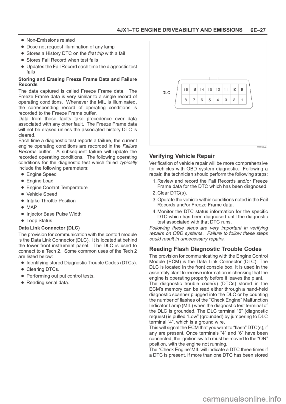
Data Link Connector (DLC)
The provision for communication with the contorl module
is the Data Link Connector (DLC). It is located at behind
the lower front instrument panel. The DLC is used to
connect to a Tech 2. Some common uses of the Tech 2
are listed below:
Identifying stored Diagnostic Trouble Codes (DTCs).
Clearing DTCs.
Performing out put control tests.
Reading serial data.
060RW046
Verifying Vehicle Repair
Verification of vehicle repair will be more comprehensive
for vehicles with OBD system diagnostic. Following a
repair, the technician should perform the following steps:
1. Review and record the Fail Records and/or Freeze
Frame data for the DTC which has been diagnosed.
2. Clear DTC(s).
3. Operate the vehicle within conditions noted in the Fail
Records and/or Freeze Frame data.
4. Monitor the DTC status information for the specific
DTC which has been diagnosed until the diagnostic
test associated with that DTC runs.
Following these steps are very important in verifying
repairs on OBD systems. Failure to follow these steps
could result in unnecessary repairs.
Reading Flash Diagnostic Trouble Codes
The provision for communicating with the Engine Control
Module (ECM) is the Data Link Connector (DLC). The
DLC is located in the front console box. It is used in the
assembly plant to receive information in checking that the
engine is operating properly before it leaves the plant.
The diagnostic trouble code(s) (DTCs) stored in the
ECM’s memory can be read either through a hand-held
diagnostic scanner plugged into the DLC or by counting
the number of flashes of the “Check Engine” Malfunction
Indicator Lamp (MIL) when the diagnostic test terminal of
the DLC is grounded. The DLC terminal “6” (diagnostic
request) is pulled “Low” (grounded) by jumpering to DLC
terminal “4”, which is a ground wire.
This will signal the ECM that you want to “flash” DTC(s), if
any are present. Once terminals “4” and “6” have been
connected, the ignition switch must be moved to the “ON”
position, with the engine not running.
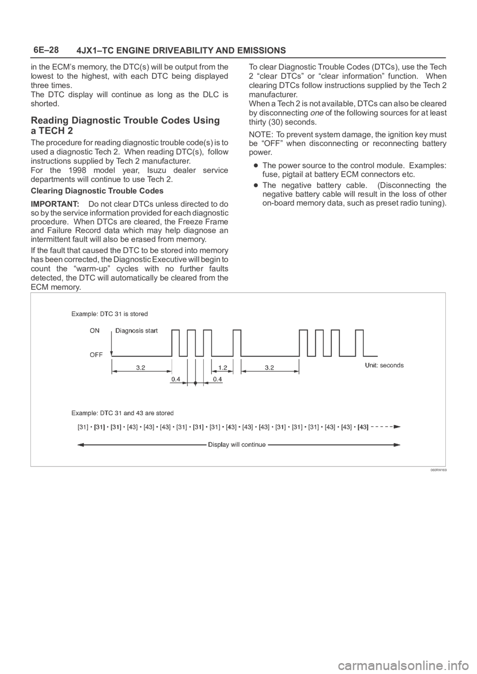
The “Check Engine”MIL will indicate a DTC three times if
a DTC is present. If more than one DTC has been stored
Page 5457 of 6000
6E–28
4JX1–TC ENGINE DRIVEABILITY AND EMISSIONS
in the ECM’s memory, the DTC(s) will be output from the
lowest to the highest, with each DTC being displayed
three times.
The DTC display will continue as long as the DLC is
shorted.
Reading Diagnostic Trouble Codes Using
a TECH 2
The procedure for reading diagnostic trouble code(s) is to
used a diagnostic Tech 2. When reading DTC(s), follow
instructions supplied by Tech 2 manufacturer.
For the 1998 model year, Isuzu dealer service
departments will continue to use Tech 2.
Clearing Diagnostic Trouble Codes
IMPORTANT:Do not clear DTCs unless directed to do
so by the service information provided for each diagnostic
procedure. When DTCs are cleared, the Freeze Frame
and Failure Record data which may help diagnose an
intermittent fault will also be erased from memory.
If the fault that caused the DTC to be stored into memory
has been corrected, the Diagnostic Executive will begin to
count the “warm-up” cycles with no further faults
detected, the DTC will automatically be cleared from the
ECM memory.To clear Diagnostic Trouble Codes (DTCs), use the Tech
2 “clear DTCs” or “clear information” function. When
clearing DTCs follow instructions supplied by the Tech 2
manufacturer.
When a Tech 2 is not available, DTCs can also be cleared
by disconnecting
one of the following sources for at least
thirty (30) seconds.
NOTE: To prevent system damage, the ignition key must
be “OFF” when disconnecting or reconnecting battery
power.
The power source to the control module. Examples:
fuse, pigtail at battery ECM connectors etc.
The negative battery cable. (Disconnecting the
negative battery cable will result in the loss of other
on-board memory data, such as preset radio tuning).
060RW169
Page 5459 of 6000
6E–30
4JX1–TC ENGINE DRIVEABILITY AND EMISSIONS
Getting Started
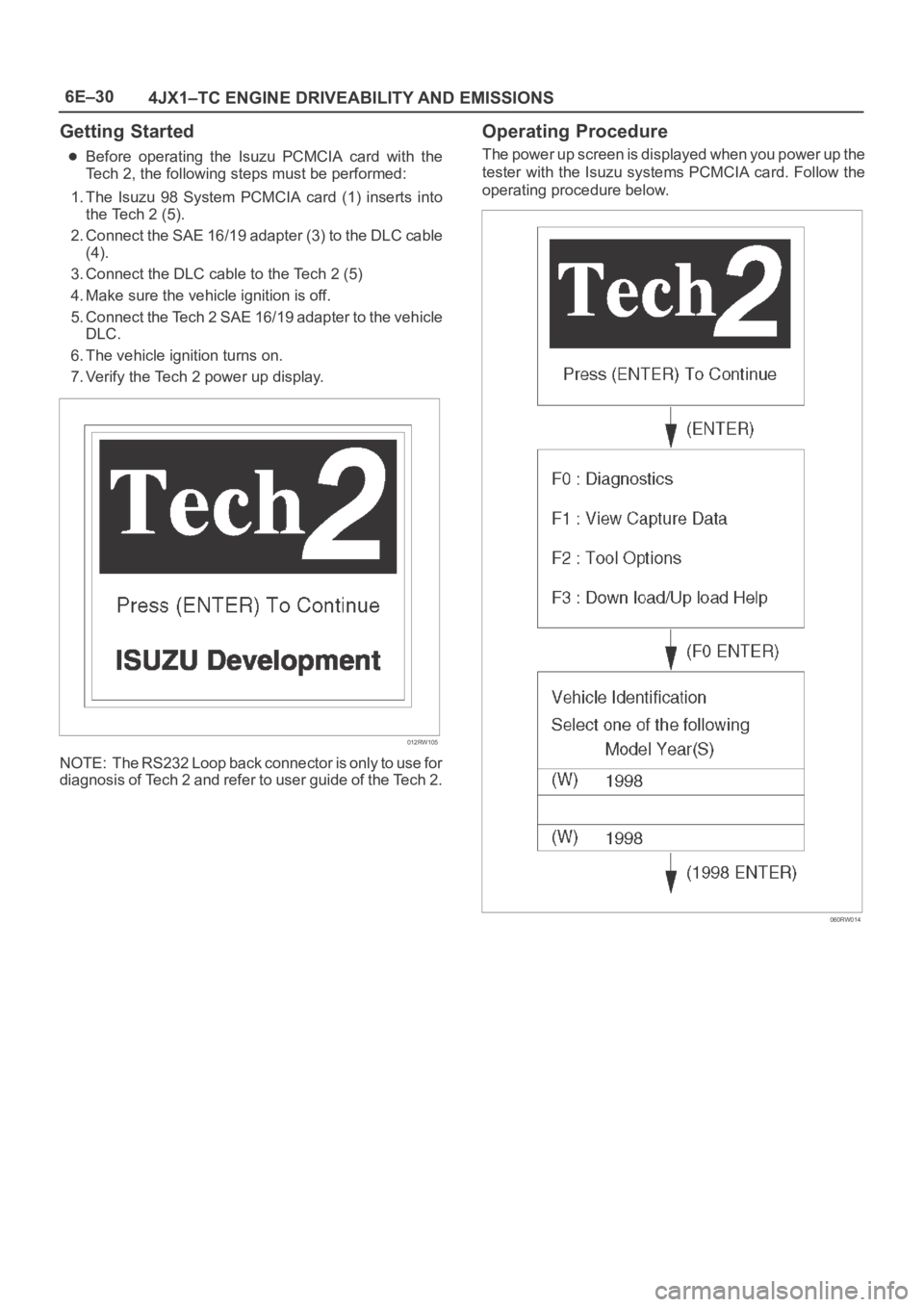
Before operating the Isuzu PCMCIA card with the
Tech 2, the following steps must be performed:
1. The Isuzu 98 System PCMCIA card (1) inserts into
the Tech 2 (5).
2. Connect the SAE 16/19 adapter (3) to the DLC cable
(4).
3. Connect the DLC cable to the Tech 2 (5)
4. Make sure the vehicle ignition is off.
5. Connect the Tech 2 SAE 16/19 adapter to the vehicle
DLC.
6. The vehicle ignition turns on.
7. Verify the Tech 2 power up display.
012RW105
NOTE: The RS232 Loop back connector is only to use for
diagnosis of Tech 2 and refer to user guide of the Tech 2.
Operating Procedure
The power up screen is displayed when you power up the
tester with the Isuzu systems PCMCIA card. Follow the
operating procedure below.
060RW014
Page 5461 of 6000
6E–32
4JX1–TC ENGINE DRIVEABILITY AND EMISSIONS
DTC Modes
There are three options available in the Tech 2 DTC mode
to display the enhanced information available. A
description of the new modes, DTC Info, follows. After
selecting DTC, the following menu appears:
DTC Info
Clear Info
Read DTC Info Ordered By Priority
The following is a brief description of each of the sub
menus in DTC Info. The order in which they appear here is
alphabetical and not necessarily the way they will appear
on the Tech 2.
DTC Information Mode
Use the DTC info mode to search for a specific type of
stored DTC information.The service manual may instruct
the technician to test for DTCs in a certain manner.
Always follow published service procedures.
Fail This Ignition
This selection will display all DTCs that have failed during
the present ignition cycle.
History
This selection will display only D T C s t h a t a r e s t o r e d i n t h e
ECM’s history memory. It will not display Type B DTCs
that have not requested the MIL (“Check Engine” lamp). It
will display all type A and B DTCs that have requested the
MIL and have failed within the last 40 warm-up cycles. In
addition, it will display all type C and type D DTCs that
have failed within the last 40 warm-up cycles.
MIL SVC or Message Requested
This selection will display only DTCs that are requesting
the MIL. Type C and type D DTCs cannot be displayed
using this option. This selection will report type B DTCs
only after the MIL has been requested.
Test Failed Since Code Cleared
This selection will display all active and history DTCs that
have reported a test failure since the last time DTCs were
cleared.
Injector Test
This test is conducted to make it sure that appropriate
electric signals are being sent to injectors Nos. 1 – 4.
Tech–2 must be used for this test.
Test Procedure:
1. Connect Tech–2 to the vehicle DLC.
2. Set Ignition Switch to the “ON” position.
3. Select Control Test.
4. Select Injector Test.
5. Send instructions to each injector(Switch on), making
sure of injector working noise.
NOTE: If injector working noise (Clink) can hardly be
confirmed, remove the engine head cover noise
insulation.
Refer to Section 6A.6. In the injector whose working noise has been
confirmed, its electric circuit can be regarded as
normal.
As for the injector whose working noise has not been
confirmed, its electric circuit or the injector proper is
faulty.
EGR Valve Test
This test is conducted to check EGR valve for its working.
This test needs Tech–2.
Test Procedure
1. Connect Tech–2 to vehicle DLC.
2. Switch on the engine.
3. Select “DIAGNOSIS” from the main menu.
4. Select Miscellaneous Test.
5. Select EGR Valve.
6. Instruct EGR Valve to check a data list.
7. If change in the data list shows a normal valve, the
working of EGR Valve can be judged to be normal.
Rail Pressure Control Valve Test
This test is conducted to check RPC valve for its working.
This test needs Tech–2.
Test Procedure
1. Connect Tech–2 to vehicle DLC.
2. Switch on the engine.
3. Select “DIAGNOSIS” from the main menu.
4. Select Miscellaneous Test.
5. Select Rail Pressure Control Valve.
6. Instruct RPC Valve to check a data list.
7. If change in the data list shows a normal valve, the
working of RPC Valve can be judged to be normal.
Injector Balance Test
This test is conducted to make it sure that appropriate
electric signals are being sent to injectors Nos. 1-4, when
the engine is idling.
This test needs Tech–2.
Test Procedure
1. Connect Tech–2 to vehicle DLC.
2. The engine is running at idling condition.
3. Select “DIAGNOSIS” from the main menu.
4. Select Miscellaneous Test.
5. Select the injector Balance Test.
6. Send instructions to each injector(Switch On),
making sure change of the engine vibration.
7. In the injector whose change of the vibration has been
confirmed, it’s electric circuit can be regarded as
normal.
Data Programming in Case of ECM Change
When replacing ECM, it is necessary to confirm and
record the group sign of injector beforehand. For this
confirmation.
Page 5462 of 6000
6E–33 4JX1–TC ENGINE DRIVEABILITY AND EMISSIONS
Tech–2 must be used. After ECM change, the recorded
group sign should be programmed. Oil pressure sensor
data also should be programmed.
Group Sign Confirmation Procedure
1 Connect Tech–2 to vehicle DLC.
2 Turn Ignition Switch to the “ON” position.
3 Select “DIAGNOSIS” from the main menu.
4 Select programming.
5 Select Read/store Trim Data.
6 Confirm and record the group sign of injector.
ECM Change
Programming Procedure for Injector Group Sign
1 Connect Tech–2 to vehicle DLC.
2 Turn Ignition Switch to the “ON” position.
3 Select “DIAGNOSIS” from the main menu.
4 Select programming.
5 Select ECM change.
6 Select cylinder.
7 Program Injector Group Sign.
8 Confirm the completion of Injector programming.
Programming Procedure for Oil Pressure Sensor
1 Connect Tech–2 to vehicle DLC.
2 Turn Ignition Switch to the “ON” position.
3 Select “DIAGNOSIS” from the main menu.
4 Select programming.
Rail Pressure Sensor Programming
Rail pressure sensor replacement must be programmed.
This programming needs Tech–2.
Programing Procedure
1. Connect Tech–2 to vehicle DLC.
2. Turn Ignition Switch to the “ON” position.
3. Select “DIAGNOSIS” from the main menu.
4. Select Programming.
5. Select Oil Pressure Sensor change.
6. Execute Oil Pressure Sensor Program.
7. Confirm the completion of Oil Pressure Sensor
Program.
Injector Group Sign Programming (Injector
Change)
In case of Injector change, injector group sign must be
programmed.
This programming needs Tech–2.
Programing Procedure
1. Connect Tech–2 to vehicle DLC.
2. Turn Ignition Switch to the “ON” position.
3. Select “DIAGNOSIS” from the main menu.
4. Select Programming.
5. Select Injector change.
6. Select the cylinder changed.
7. Appoint and select Injector Group Sign.
8. Confirm the completion of Injector programming.