check engine OPEL FRONTERA 1998 Workshop Manual
[x] Cancel search | Manufacturer: OPEL, Model Year: 1998, Model line: FRONTERA, Model: OPEL FRONTERA 1998Pages: 6000, PDF Size: 97 MB
Page 5382 of 6000
ENGINE FUEL 6C – 1
ENGINE FUEL
CONTENTS
GENERAL DESCRIPTION
General Description . . . . . . . . . . . . . . . . . . 6C–1
On-Vehicle Service . . . . . . . . . . . . . . . . . . 6C–8
Fuel Filter Assembly . . . . . . . . . . . . . . . . 6C–8
Fuel Filter Cartridge . . . . . . . . . . . . . . . . 6C–8
Injector . . . . . . . . . . . . . . . . . . . . . . . . . . 6C–10High Pressure Oil Pump . . . . . . . . . . . . . 6C–14
Fuel Tank . . . . . . . . . . . . . . . . . . . . . . . . 6C–20
Fuel Gauge Unit . . . . . . . . . . . . . . . . . . . 6C–21
Fuel Filler Cap . . . . . . . . . . . . . . . . . . . . 6C–21
To realize the compatibility between low exhaust
emission and high engine output, an HEUI
(Hydraulically actuated Electronically controlled Unit
Injector) system, has been introduced. This system is
comprised of a hydraulic system, fuel system, and
electronic control system, using a high-pressure oil
pump in place of the conventional fuel injection pump.
The oil pressurized by means of this pump and by
signals from the ECM (Electronic Control Module)
actuates the fuel injector provided for each cylinder.
Inside of the fuel injector, fuel pressure is increased due
to the high-pressure oil. The ECM detects the driving
state of the vehicle, forms, signals sent by engine and
other part sensors, which determines the optimum fuel
injection amount and timing, thus controlling the fuel
injectors. Thus high engine output, good fuel economy,
and low exhaust emission are realized.When working on the fuel system, there are several
things to keep in mind:
1) Any time the fuel system is being worked on,
disconnect the negative battery cable except for
those tests where battery voltage is required.
2)Always keep a dry chemical (Class B) fire
extinguisher near the work area.
3) Replace all pipes with the same pipe and fittings
that were removed.
Clean and inspect “O” rings. Replace where
required.
4) Always relieve the line pressure before servicing
any fuel system components.
5) Do not attempt repairs on the fuel system until you
have read the instructions and checked the pictures
relating to that repair.
6) After maintenance work, push priming pump and
send enough fuel to the fuel system before starting
the engine.
NOTE: In comparison with the conventional engine,
the capacity of fuel passage in the 4JX1 engine is
larger. It takes the priming pump more time to fill the
engine with fuel.
Page 5386 of 6000
ENGINE FUEL 6C – 5
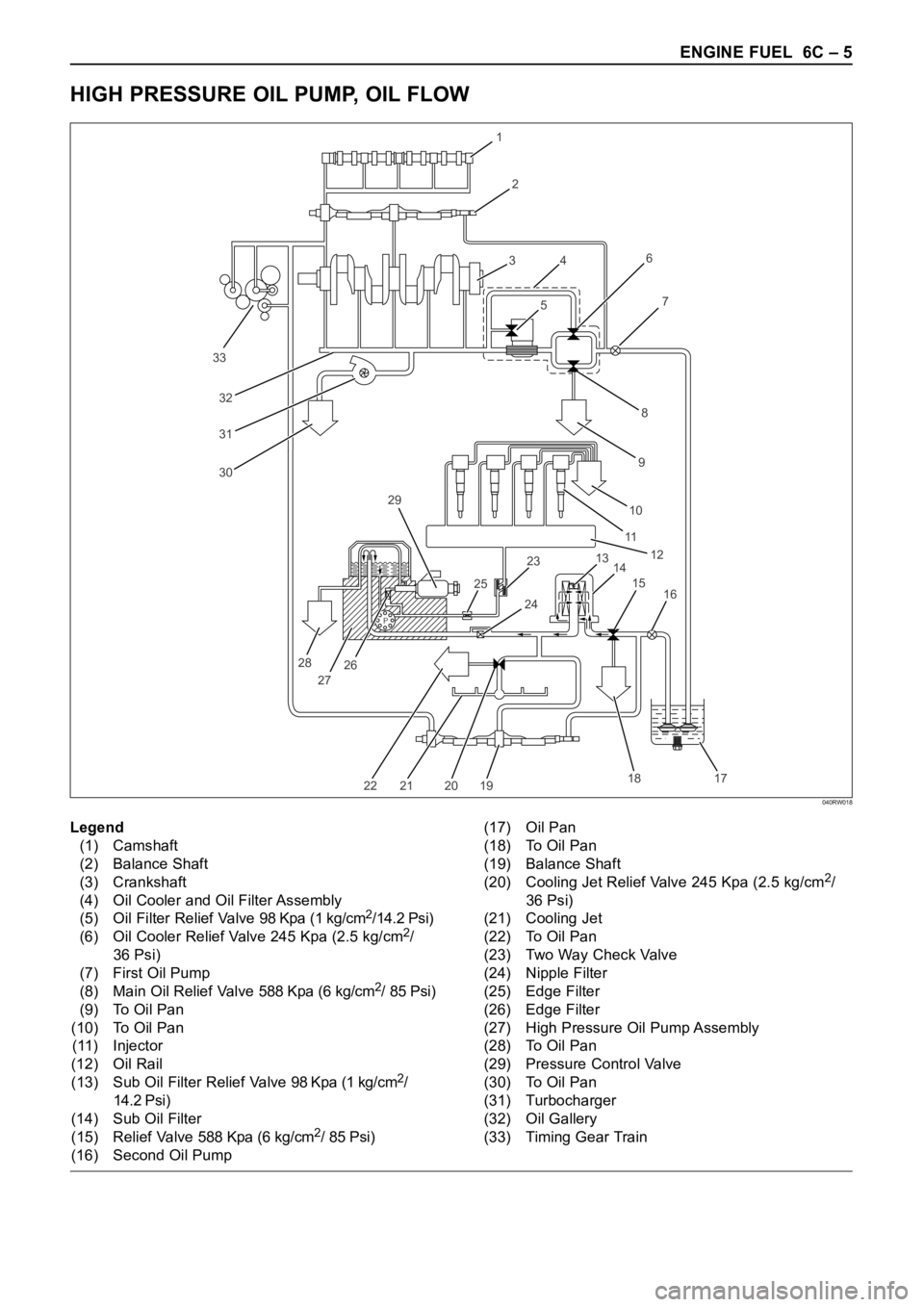
HIGH PRESSURE OIL PUMP, OIL FLOW
P
33
32
31
30
1
2
3
4
56
8
97
10
11
12
13
14 23 29
25
28
27262415
16
17 18
19 20 21 22
Legend
(1) Camshaft
(2) Balance Shaft
(3) Crankshaft
(4) Oil Cooler and Oil Filter Assembly
(5) Oil Filter Relief Valve 98 Kpa (1 kg/cm
2/14.2 Psi)
(6) Oil Cooler Relief Valve 245 Kpa (2.5 kg/cm2/
36 Psi)
(7) First Oil Pump
(8) Main Oil Relief Valve 588 Kpa (6 kg/cm
2/ 85 Psi)
(9) To Oil Pan
(10) To Oil Pan
(11) Injector
(12) Oil Rail
(13) Sub Oil Filter Relief Valve 98 Kpa (1 kg/cm
2/
14.2 Psi)
(14) Sub Oil Filter
(15) Relief Valve 588 Kpa (6 kg/cm
2/ 85 Psi)
(16) Second Oil Pump(17) Oil Pan
(18) To Oil Pan
(19) Balance Shaft
(20) Cooling Jet Relief Valve 245 Kpa (2.5 kg/cm
2/
36 Psi)
(21) Cooling Jet
(22) To Oil Pan
(23) Two Way Check Valve
(24) Nipple Filter
(25) Edge Filter
(26) Edge Filter
(27) High Pressure Oil Pump Assembly
(28) To Oil Pan
(29) Pressure Control Valve
(30) To Oil Pan
(31) Turbocharger
(32) Oil Gallery
(33) Timing Gear Train
040RW018
Page 5399 of 6000
6C – 18 ENGINE FUEL
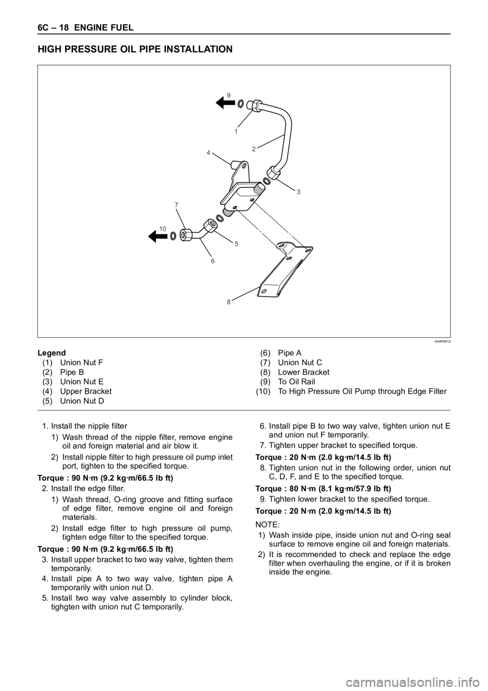
HIGH PRESSURE OIL PIPE INSTALLATION
1. Install the nipple filter
1) Wash thread of the nipple filter, remove engine
oil and foreign material and air blow it.
2) Install nipple filter to high pressure oil pump inlet
port, tighten to the specified torque.
Torque : 90 Nꞏm (9.2 kgꞏm/66.5 lb ft)
2. Install the edge filter.
1) Wash thread, O-ring groove and fitting surface
of edge filter, remove engine oil and foreign
materials.
2) Install edge filter to high pressure oil pump,
tighten edge filter to the specified torque.
Torque : 90 Nꞏm (9.2 kgꞏm/66.5 lb ft)
3. Install upper bracket to two way valve, tighten them
temporarily.
4. Install pipe A to two way valve, tighten pipe A
temporarily with union nut D.
5. Install two way valve assembly to cylinder block,
tighgten with union nut C temporarily.6. Install pipe B to two way valve, tighten union nut E
and union nut F temporarily.
7. Tighten upper bracket to specified torque.
Torque : 20 Nꞏm (2.0 kgꞏm/14.5 lb ft)
8. Tighten union nut in the following order, union nut
C, D, F, and E to the specified torque.
Torque : 80 Nꞏm (8.1 kgꞏm/57.9 lb ft)
9. Tighten lower bracket to the specified torque.
Torque : 20 Nꞏm (2.0 kgꞏm/14.5 lb ft)
NOTE:
1) Wash inside pipe, inside union nut and O-ring seal
surface to remove engine oil and foreign materials.
2) It is recommended to check and replace the edge
filter when overhauling the engine, or if it is broken
inside the engine.
1
2
3
5
6
8 9
7
104
Legend
(1) Union Nut F
(2) Pipe B
(3) Union Nut E
(4) Upper Bracket
(5) Union Nut D(6) Pipe A
(7) Union Nut C
(8) Lower Bracket
(9) To Oil Rail
(10) To High Pressure Oil Pump through Edge Filter
040RW015
Page 5400 of 6000

ENGINE FUEL 6C – 19
Nipple Filter and Edge Filter Installation
The nipple filter is provided at the front of the inlet port
side. The edge filter is provided at the rear of the outlet
port on the high pressure oil pump assembly.
1. Install the nipple filter
1) Wash threads and filter to remove engine oil and
foreign materials before installing the nipple
filter.
2) Install the nipple filter to the inlet port of high
pressure oil pump, tighten to the specified
torque.
Torque : 90 Nꞏm (9.2 kgꞏm/66.5 lb ft)
(Tighten dry condition)
2. Install the edge filter.
1) Wash threads and O-ring groove and part fitting
surface to remove engine oil and foreign
materials before installing the nipple filter.
2) Install edge filter to outlet port of high pressure
oil pump, tighten to the specified torque.
Torque : 90 Nꞏm (9.2 kgꞏm/66.5 lb ft)
(Tighten dry condition)
NOTE: It is recommended to check and replace the
edge filter when overhauling the engine, or if it is broken
inside the engine.
Page 5402 of 6000
ENGINE FUEL 6C – 21
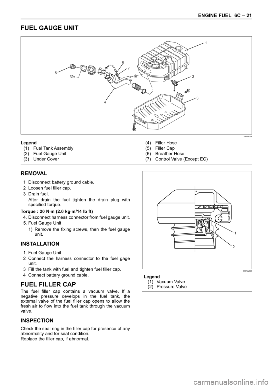
FUEL GAUGE UNIT
1
2
6
7
4
5
3
140RX023
REMOVAL
1 Disconnect battery ground cable.
2 Loosen fuel filler cap.
3 Drain fuel.
After drain the fuel tighten the drain plug with
specified torque.
Torque : 20 Nꞏm (2.0 kgꞏm/14 lb ft)
4. Disconnect harness connector from fuel gauge unit.
5. Fuel Gauge Unit
1) Remove the fixing screws, then the fuel gauge
unit.
INSTALLATION
1. Fuel Gauge Unit
2 Connect the harness connector to the fuel gage
unit.
3 Fill the tank with fuel and tighten fuel filler cap.
4 Connect battery ground cable.
FUEL FILLER CAP
The fuel filler cap contains a vacuum valve. If a
negative pressure develops in the fuel tank, the
external valve of the fuel filler cap opens to allow the
fresh air to flow into the fuel tank through the vacuum
valve.
INSPECTION
Check the seal ring in the filler cap for presence of any
abnormality and for seal condition.
Replace the filler cap, if abnormal.Legend
(1) Vacuum Valve
(2) Pressure Valve Legend
(1) Fuel Tank Assembly
(2) Fuel Gauge Unit
(3) Under Cover(4) Filler Hose
(5) Filler Cap
(6) Breather Hose
(7) Control Valve (Except EC)
1
2
060RW098
Page 5404 of 6000
ENGINE ELECTRICAL 6D – 1
ENGINE ELECTRICAL
CONTENTS
Battery . . . . . . . . . . . . . . . . . . . . . . . . . . . . 6D–1
General Description . . . . . . . . . . . . . . . . 6D–1
Diagnosis . . . . . . . . . . . . . . . . . . . . . . . . 6D–1
On Vehicle Service . . . . . . . . . . . . . . . . . 6D–3
Main Data and Specification . . . . . . . . . . 6D–4
Starting System . . . . . . . . . . . . . . . . . . . . . 6D–5
General Description . . . . . . . . . . . . . . . . 6D–5
On Vehicle Service . . . . . . . . . . . . . . . . . 6D–7
Starter . . . . . . . . . . . . . . . . . . . . . . . . . . 6D–7
Unit Repair . . . . . . . . . . . . . . . . . . . . . . . 6D–8Charging System . . . . . . . . . . . . . . . . . . . . 6D–15
General Description . . . . . . . . . . . . . . . . 6D–15
Diagnosis . . . . . . . . . . . . . . . . . . . . . . . . 6D–16
Unit Repair . . . . . . . . . . . . . . . . . . . . . . . 6D–17
Main Data and Specification . . . . . . . . . . 6D–22
QOS4 Preheating System . . . . . . . . . . . . . . 6D–23
General Description . . . . . . . . . . . . . . . . 6D–23
System Diagram . . . . . . . . . . . . . . . . . . . 6D–23
Inspection of QOS4 System Operation . . 6D–24
BATTERY
GENERAL DESCRIPTION
DIAGNOSIS
There are six battery fluid caps at the top of the battery.
These are covered by a paper label.
The battery is completely sealed except for the six
small vent holes at the side. These vent holes permit
the escape of small amounts of gas generated by the
battery.
This type of battery has the following advantages over
conventional batteries:1. There is no need to add water during the entire
service life of the battery.
2. The battery protects itself against overcharging.
The battery will refuse to accept an excessive
charge.
(A conventional battery will accept an excessive
charge, resulting in gassing and loss of battery
fluid.)
3. The battery is much less vulnerable to self-
discharge than a conventional type battery.
1. VISUAL INSPECTION (Step 1)
Inspect the battery for obvious physical damage, such
as a cracked or broken case, which would permit
electrolyte loss.
Replace the battery if obvious physical damage is
discovered during inspection.
Check for any other physical damage and correct it as
necessary. If not, proceed to Step 2.
2. HYDROMETER CHECK (Step 2)
There is a built-in hydrometer (Charge test indicator) at
the top of the battery. It is designed to be used during
diagnostic procedures.
Before trying to read the hydrometer, carefully clean the
upper battery surface.
If your work area is poorly lit, additional light may be
necessary to read the hydrometer.
a. BLUE RING OR DOT VISIBLE – Go to Step 4.
b. BLUE RING OR DOT NOT VISIBLE – Go to
Step 3.3. FLUID LEVEL CHECK (Step 3)
The fluid level should be between the upper level line
and lower level line on side of the battery.
a. CORRECT FLUID LEVEL – Charge the battery.
b. BELOW LOWER LEVEL – Replace battery.
4. VOLTAGE CHECK (Step 4)
(1) Put voltmeter test leads to battery terminals.
a. VOLTAGE IS 12.4V OR ABOVE – Go to Step 5.
b. VOLTAGE IS UNDER 12.4V – Go to procedure
(2) below.
(2) Determine fast charge amperage from
specification. (See Main Data and Specifications in
this section.)
Fast charge battery for 30 minutes at amperage
rate no higher than specified value.
Take voltage and amperage readings after charge.
a. VOLTAGE IS ABOVE 16V AT BELOW 1/3 OF
AMPERAGE RATE – Replace battery.
Page 5413 of 6000
6D – 10 ENGINE ELECTRICAL
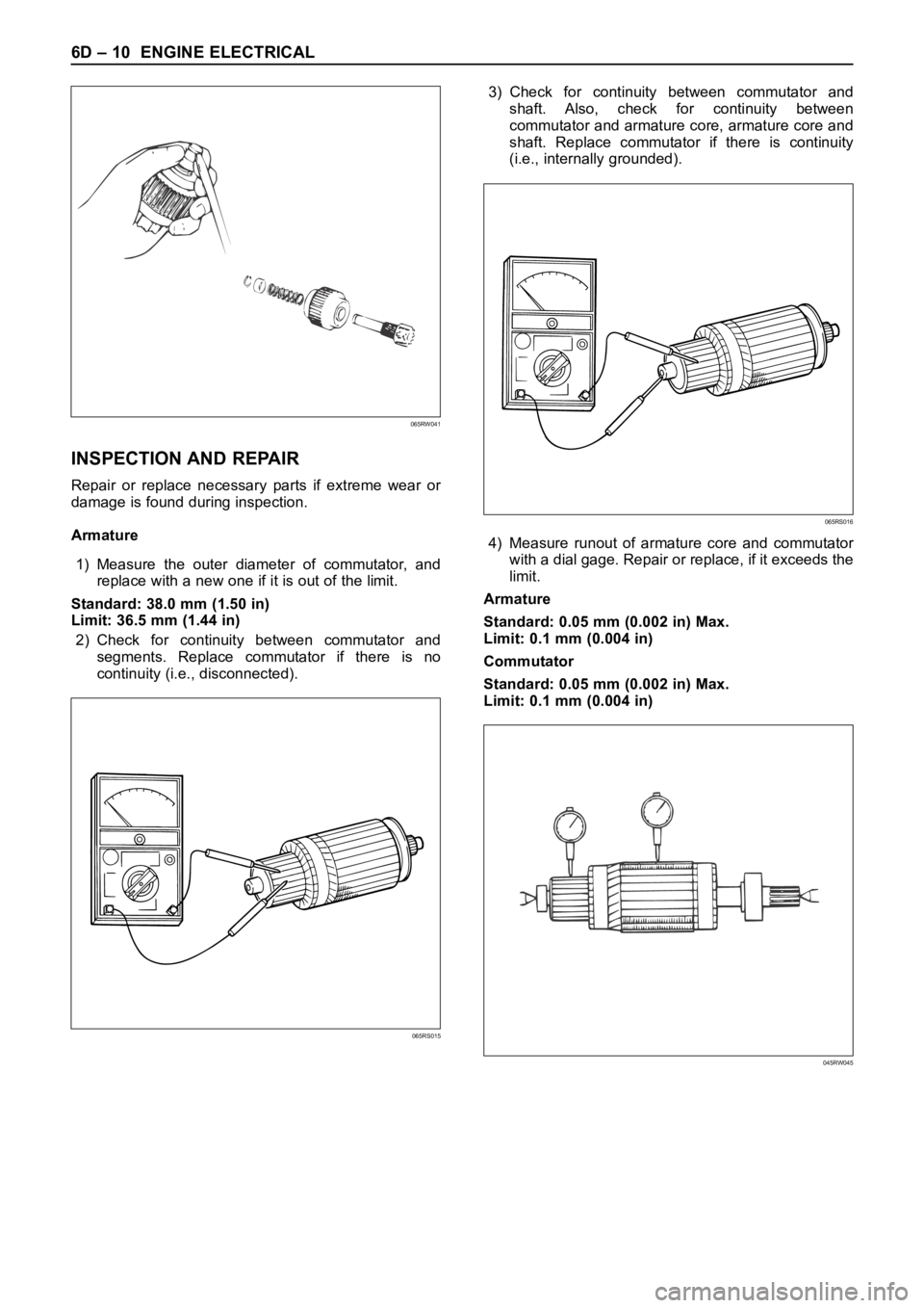
INSPECTION AND REPAIR
Repair or replace necessary parts if extreme wear or
damage is found during inspection.
Armature
1) Measure the outer diameter of commutator, and
replace with a new one if it is out of the limit.
Standard: 38.0 mm (1.50 in)
Limit: 36.5 mm (1.44 in)
2) Check for continuity between commutator and
segments. Replace commutator if there is no
continuity (i.e., disconnected).3) Check for continuity between commutator and
shaft. Also, check for continuity between
commutator and armature core, armature core and
shaft. Replace commutator if there is continuity
(i.e., internally grounded).
4) Measure runout of armature core and commutator
with a dial gage. Repair or replace, if it exceeds the
limit.
Armature
Standard: 0.05 mm (0.002 in) Max.
Limit: 0.1 mm (0.004 in)
Commutator
Standard: 0.05 mm (0.002 in) Max.
Limit: 0.1 mm (0.004 in)
065RW041
065RS015
065RS016
045RW045
Page 5414 of 6000
ENGINE ELECTRICAL 6D – 11
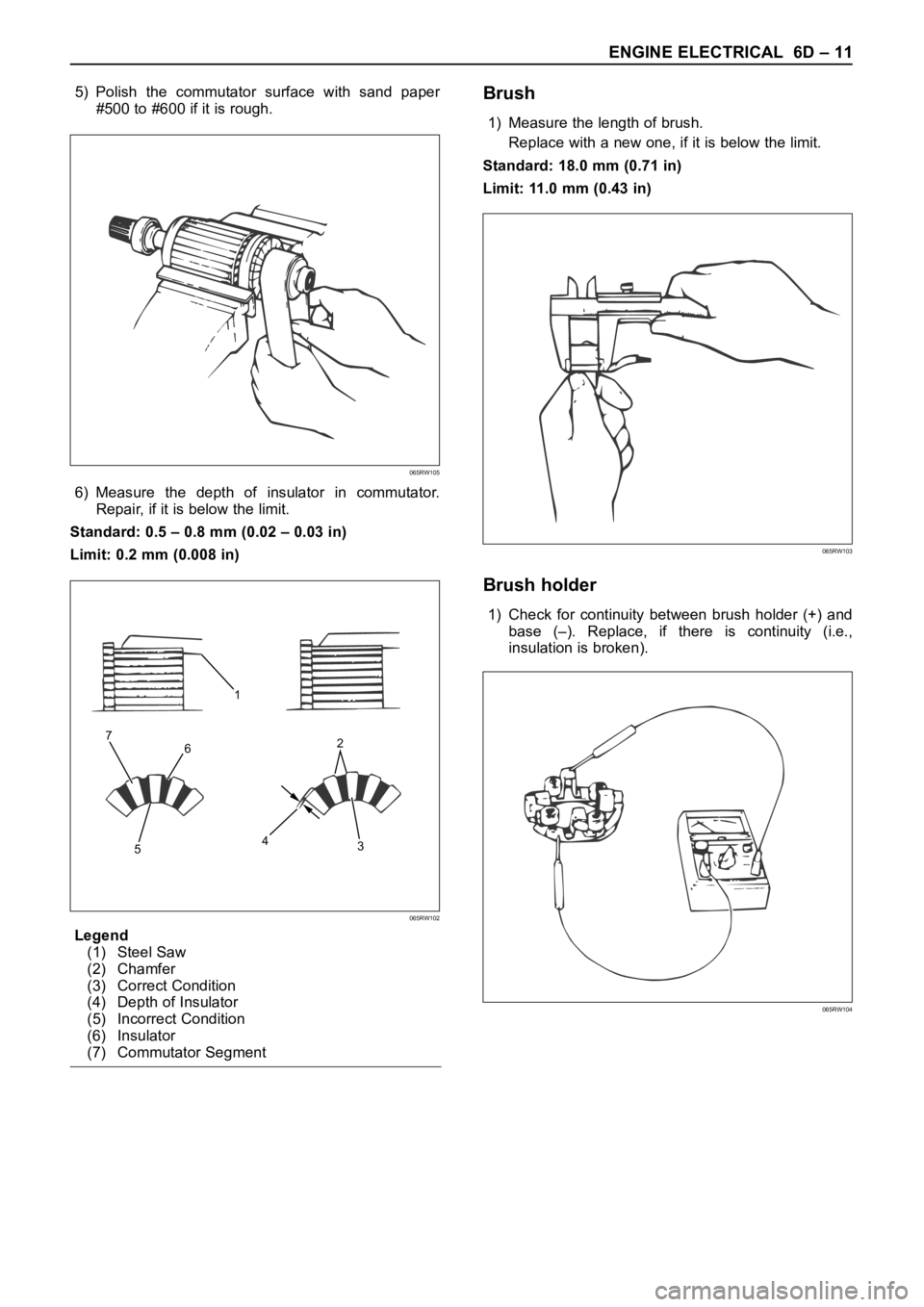
5) Polish the commutator surface with sand paper
#500 to #600 if it is rough.
6) Measure the depth of insulator in commutator.
Repair, if it is below the limit.
Standard: 0.5 – 0.8 mm (0.02 – 0.03 in)
Limit: 0.2 mm (0.008 in)
Legend
(1) Steel Saw
(2) Chamfer
(3) Correct Condition
(4) Depth of Insulator
(5) Incorrect Condition
(6) Insulator
(7) Commutator SegmentBrush
1) Measure the length of brush.
Replace with a new one, if it is below the limit.
Standard: 18.0 mm (0.71 in)
Limit: 11.0 mm (0.43 in)
Brush holder
1) Check for continuity between brush holder (+) and
base (–). Replace, if there is continuity (i.e.,
insulation is broken).
065RW105
1
6
53 42 7
065RW102
065RW103
065RW104
Page 5415 of 6000
6D – 12 ENGINE ELECTRICAL
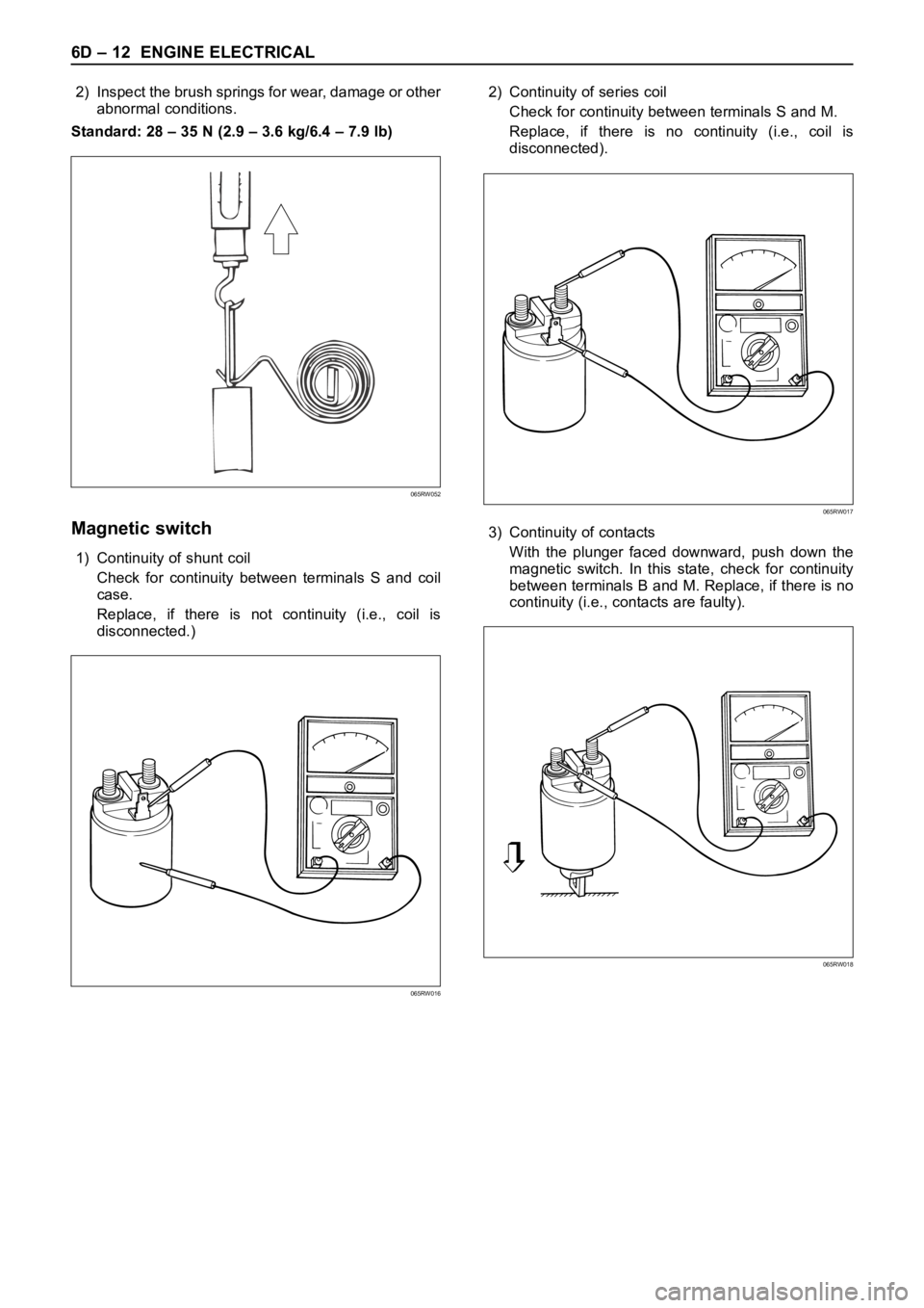
2) Inspect the brush springs for wear, damage or other
abnormal conditions.
Standard: 28 – 35 N (2.9 – 3.6 kg/6.4 – 7.9 lb)
Magnetic switch
1) Continuity of shunt coil
Check for continuity between terminals S and coil
case.
Replace, if there is not continuity (i.e., coil is
disconnected.)2) Continuity of series coil
Check for continuity between terminals S and M.
Replace, if there is no continuity (i.e., coil is
disconnected).
3) Continuity of contacts
With the plunger faced downward, push down the
magnetic switch. In this state, check for continuity
between terminals B and M. Replace, if there is no
continuity (i.e., contacts are faulty).
065RW052
065RW017
065RW018
065RW016
Page 5416 of 6000
ENGINE ELECTRICAL 6D – 13
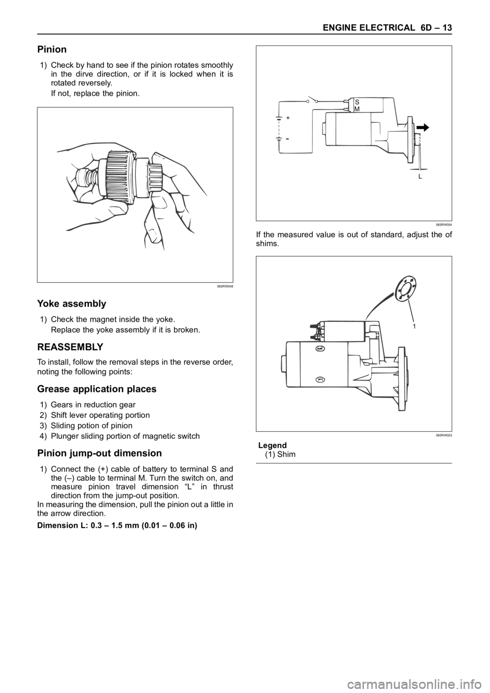
Pinion
1) Check by hand to see if the pinion rotates smoothly
in the dirve direction, or if it is locked when it is
rotated reversely.
If not, replace the pinion.
Yoke assembly
1) Check the magnet inside the yoke.
Replace the yoke assembly if it is broken.
REASSEMBLY
To install, follow the removal steps in the reverse order,
noting the following points:
Grease application places
1) Gears in reduction gear
2) Shift lever operating portion
3) Sliding potion of pinion
4) Plunger sliding portion of magnetic switch
Pinion jump-out dimension
1) Connect the (+) cable of battery to terminal S and
the (–) cable to terminal M. Turn the switch on, and
measure pinion travel dimension “L” in thrust
direction from the jump-out position.
In measuring the dimension, pull the pinion out a little in
the arrow direction.
Dimension L: 0.3 – 1.5 mm (0.01 – 0.06 in)If the measured value is out of standard, adjust the of
shims.
Legend
(1) Shim
065RW048
S
+
L M
065RW054
1
065RW053