check engine OPEL FRONTERA 1998 Workshop Manual
[x] Cancel search | Manufacturer: OPEL, Model Year: 1998, Model line: FRONTERA, Model: OPEL FRONTERA 1998Pages: 6000, PDF Size: 97 MB
Page 5365 of 6000
6A – 92 ENGINE MECHANICAL
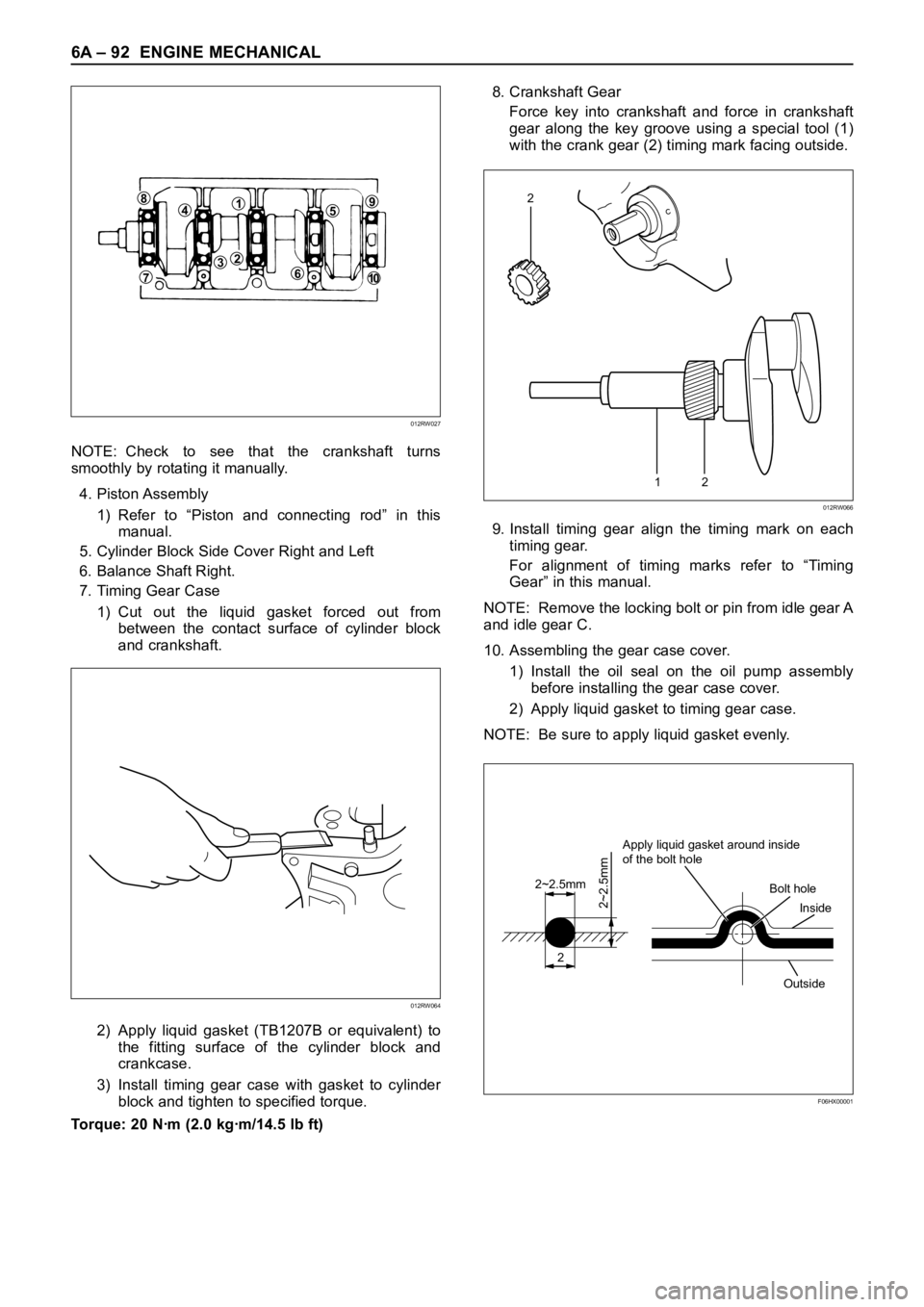
NOTE: Check to see that the crankshaft turns
smoothly by rotating it manually.
4. Piston Assembly
1) Refer to “Piston and connecting rod” in this
manual.
5. Cylinder Block Side Cover Right and Left
6. Balance Shaft Right.
7. Timing Gear Case
1) Cut out the liquid gasket forced out from
between the contact surface of cylinder block
and crankshaft.
2) Apply liquid gasket (TB1207B or equivalent) to
the fitting surface of the cylinder block and
crankcase.
3) Install timing gear case with gasket to cylinder
block and tighten to specified torque.
Torque: 20 Nꞏm (2.0 kgꞏm/14.5 lb ft)8. Crankshaft Gear
Force key into crankshaft and force in crankshaft
gear along the key groove using a special tool (1)
with the crank gear (2) timing mark facing outside.
9. Install timing gear align the timing mark on each
timing gear.
For alignment of timing marks refer to “Timing
Gear” in this manual.
NOTE: Remove the locking bolt or pin from idle gear A
and idle gear C.
10. Assembling the gear case cover.
1) Install the oil seal on the oil pump assembly
before installing the gear case cover.
2) Apply liquid gasket to timing gear case.
NOTE: Be sure to apply liquid gasket evenly.
84159
610
237
012RW027
012RW064
12
2
012RW066
2
2~2.5mm
2~2.5mm
Apply liquid gasket around inside
of the bolt hole
Bolt hole
Inside
Outside
F06HX00001
Page 5366 of 6000

ENGINE MECHANICAL 6A – 93
11. Use the special tool to install the crankshaft front oil
seal to timing gear case.
Front Oil Seal Installer: 5-8840-2061-0
1) Check fit-of the oil seal and gear case cover at
the front end.
Standard: 0.5 – 2.5 mm (0.0197 – 0.0984 in)
NOTE: Apply engine oil to oil seal lip before installation
of the seal.
12. Install the oil pan assembly to original position and
tighten to specified torque.
Torque: 22 Nꞏm (2.2 kgꞏm/15.9 lb ft)
13. Crankshaft Rear Oil Seal
1) Tighten the adapter to the crankshaft rear end
with 2 bolts.
2) Insert the oil seal into the adapter.
3) Insert the sleeve into the adapter and tighten it
with a bolt (M12 x 1.75L = 70) until the adapter
hits the sleeve.
4) Remove the adapter and the sleeve.
5) With the seal pressed in, check the dimension of
the oil seal outside end and crankshaft end.
Standard Dimension = 12.5 ± 0.3 mm
Oil Seal Installer: 5-8840-2359-014. Cylinder Block Rear Plate (A/T Model)
1) Tighten the cylinder block rear plate fixing bolts
to the specified torque.
Torque: 97 Nꞏm (9.9 kgꞏm/72 lb ft)
15. Flywheel Housing (M/T Model)
1) Install flywheel housing aligned with the dowel
pin on the cylinder block.
2) Tighten the flywheel housing fixing bolts to the
specified torque.
Torque: 97 Nꞏm (9.9 kgꞏm/72 lb ft)
16. Flywheel
1) Refer to “Crankshaft” in this manual.
17. Cylinder Head Assembly
1) Refer to “Cylinder Head” in this manual.
015RW074
12.5 + 0.3–
012RW067
Page 5368 of 6000
ENGINE MECHANICAL 6A – 95
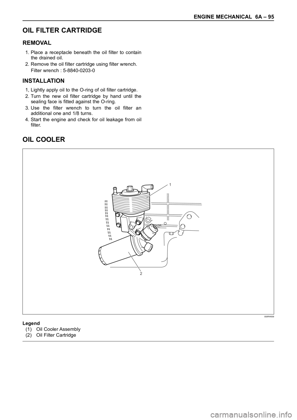
OIL COOLER
1
2
050RW009
Legend
(1) Oil Cooler Assembly
(2) Oil Filter Cartridge
OIL FILTER CARTRIDGE
REMOVAL
1. Place a receptacle beneath the oil filter to contain
the drained oil.
2. Remove the oil filter cartridge using filter wrench.
Filter wrench : 5-8840-0203-0
INSTALLATION
1, Lightly apply oil to the O-ring of oil filter cartridge.
2. Turn the new oil filter cartridge by hand until the
sealing face is fitted against the O-ring.
3. Use the filter wrench to turn the oil filter an
additional one and 1/8 turns.
4. Start the engine and check for oil leakage from oil
filter.
Page 5369 of 6000

6A – 96 ENGINE MECHANICAL
REMOVAL
1. Disconnect battery ground cable
2. Drain engine coolant
3. Remove front exhaust pipe
4. Remove heat protector
5. Remove exhaust valve assembly
6. Oil cooler assembly
1) Remove water hoses from inlet and outlet pipe.
2) Put rag beneath side of oil cooler to prevent oil
leaking.
3) Remove fixing bolts and oil cooler assembly.
INSTALLATION
1. Oil Cooler
1) Tighten oil cooler fixing bolt to the specified
torque and connect water hose.
Torque: 29 Nꞏm (3.0 kgꞏm/22 lb ft)
2. Exh. Valve Assembly
1) Install exhaust valve assembly with gasket and
tighten fixing bolts to the specified torque.
Torque: 27 Nꞏm (2.7 kgꞏm/20 lb ft)
3. Heat Protector
4. Front Exhaust Pipe
1) Install front exhaust pipe and tighten fixing bolts
to the specified torque.
Exh. Valve Side: 67 Nꞏm (6.8 kgꞏm/50 lb ft)
Intermediate Pipe Side: 43 Nꞏm (4.4 kgꞏm/32 lb ft)
5. Fill engine coolant.
6. Connect battery ground cable.
7. Start engine and check for oil and water leakage
carefully.
Page 5373 of 6000
6B – 4 ENGINE COOLING
ANTI-FREEZE SOLUTION
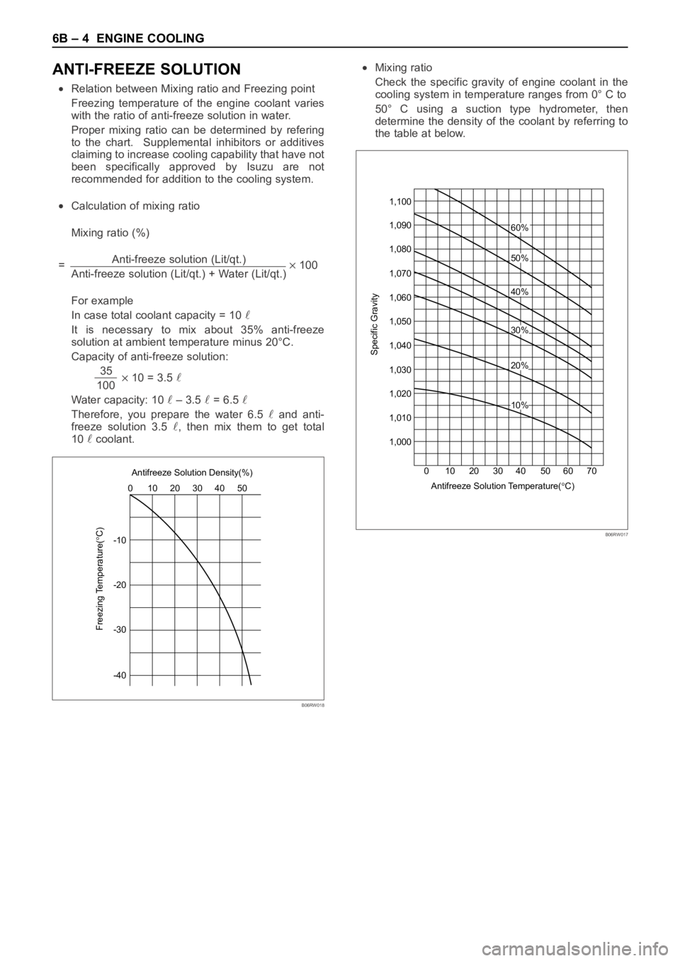
Relation between Mixing ratio and Freezing point
Freezing temperature of the engine coolant varies
with the ratio of anti-freeze solution in water.
Proper mixing ratio can be determined by refering
to the chart. Supplemental inhibitors or additives
claiming to increase cooling capability that have not
been specifically approved by Isuzu are not
recommended for addition to the cooling system.
Calculation of mixing ratio
Mixing ratio (%)
=Anti-freeze solution (Lit/qt.)
100
Anti-freeze solution (Lit/qt.) + Water (Lit/qt.)
For example
In case total coolant capacity = 10
It is necessary to mix about 35% anti-freeze
solution at ambient temperature minus 20°C.
Capacity of anti-freeze solution:
35
10 = 3.5 100
Water capacity: 10
– 3.5 = 6.5
Therefore, you prepare the water 6.5 and anti-
freeze solution 3.5
, then mix them to get total
10
coolant.
Mixing ratio
Check the specific gravity of engine coolant in the
cooling system in temperature ranges from 0° C to
50° C using a suction type hydrometer, then
determine the density of the coolant by referring to
the table at below.
-1010 0
Freezing Temperature(
C)
20 30 Antifreeze Solution Density(%)
40 50
-20
-30
-40
B06RW018
1,100
20 10 30 4060%
50%
40%
20%
10%
30%
Antifreeze Solution Temperature(
C) 50 60 70 0
Specific Gravity
1,090
1,080
1,070
1,060
1,050
1,040
1,030
1,020
1,010
1,000
B06RW017
Page 5374 of 6000

ENGINE COOLING 6B – 5
ENGINE COOLANT CHANGE
PROCEDURE
1. To change engine coolant, make sure that the
engine is cool.
WARNING:
When the coolant is heated to a high temperature,
be sure not to loosen or remove the radiator cap.
Otherwise you might get scalded by hot vapor or
boiling water. To open the radiator cap, put a piece
of thick cloth on the cap and loosen the cap slowly
to reduce the pressure once the coolant has
become cooler.
2. Open radiator cap and drain the cooling system by
loosening the drain valve on the radiator and on the
cylinder body.
NOTE: For best results it is suggested that the engine
cooling system be flushed at least once a year. It is
advisable to flush the interior of the cooling system
including the radiator before using anti-freeze
(ethylene-glycol based).
Replace damaged rubber hoses as the engine anti-
freeze coolant is liable to leak out even minor cracks.
Isuzu recommends using Isuzu genuine anti-freeze
(ethylene-glycol based) or equivalent, for the cooling
system and not add any inhibitors or additives.
CAUTION:
A failure to correctly fill the engine cooling system
in changing or topping off coolant may sometimes
cause the coolant to overflow from the filler neck
even before the engine and radiator are completely
full.
If the engine runs under this condition, shortage of
coolant may possibly result in engine overheating.
To avoid such trouble, the following precautions
should be taken in filling the system.
3. To refill engine coolant, pour coolant up to filler neck
using a filling hose which is smaller in outside
diameter than the filler neck. Otherwise air between
the filler neck and the filling hose will block entry,
preventing the system from completely filling up.
4. Keep a filling rate of 9 liter/min. or less. Filling over
this maximum rate may force air inside the engine
and radiator.
And also, the coolant overflow will increase, making
it difficult to determine whether or not the system is
completely full.
5. After filling the system full, pull out the filling hose
and check to see if air trapped in the system is
dislodged and the coolant level goes down. Should
the coolant level go down, repeat topping-off until
there is no more drop in the coolant level.
6. Directly after filling the radiator, fill the reservoir to
the maximum level.
7. Install and tighten radiator cap and start the engine.
After idling for 2 to 3 minutes, stop the engine and
reopen radiator cap. If the water level is lower,
replenish.WARNING:
When the coolant is heated to a high temperature,
be sure not to loosen or remove the radiator cap.
Otherwise you might get scalded by hot vapor or
boiling water. To open the radiator cap, put a piece
of thick cloth on the cap and loosen the cap slowly
to reduce the pressure once the coolant has
become cooler.
8. After tightening radiator cap, warm up the engine at
about 2,000 rpm.
Set heater adjustment to the highest temperature
position, and let the coolant circulate also into
heater water system.
9. Check to see the thermostat has opened by the
needle position of a water thermometer, conduct a
5-minute idle again and stop the engine.
10. When the engine has been cooled, check filler neck
for water level and replenish if required. Should
extreme shortage of coolant be found, check the
coolant system and reservoir tank hose for leakage.
11. Fill the coolant into the reservoir tank up to “MAX”
line.
Page 5377 of 6000

6B – 8 ENGINE COOLING
INSTALLATION
1. Thermostat
1) The jiggle valve of the thermostat must face the
cylinder head side.
2. Gasket
3. Install thermostat housing and tighten bolt to the
specified torque.
Torque: 20 Nꞏm (2.0 kgꞏm/14.5 lb ft)
4. Reconnect water hose
1) Fill coolant to full level.
2) Reconnect battery ground cable.
5. Start the engine check for coolant leakage.
Page 5378 of 6000
ENGINE COOLING 6B – 9
RADIATOR
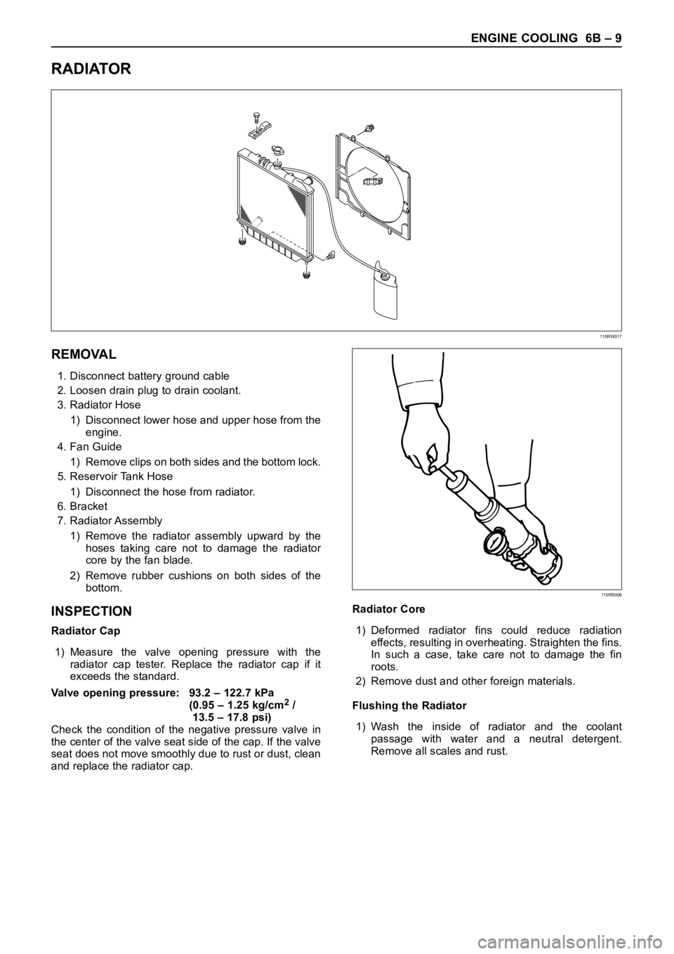
REMOVAL
1. Disconnect battery ground cable
2. Loosen drain plug to drain coolant.
3. Radiator Hose
1) Disconnect lower hose and upper hose from the
engine.
4. Fan Guide
1) Remove clips on both sides and the bottom lock.
5. Reservoir Tank Hose
1) Disconnect the hose from radiator.
6. Bracket
7. Radiator Assembly
1) Remove the radiator assembly upward by the
hoses taking care not to damage the radiator
core by the fan blade.
2) Remove rubber cushions on both sides of the
bottom.
INSPECTION
Radiator Cap
1) Measure the valve opening pressure with the
radiator cap tester. Replace the radiator cap if it
exceeds the standard.
Valve opening pressure: 93.2 – 122.7 kPa
(0.95 – 1.25 kg/cm
2/
13.5 – 17.8 psi)
Check the condition of the negative pressure valve in
the center of the valve seat side of the cap. If the valve
seat does not move smoothly due to rust or dust, clean
and replace the radiator cap.Radiator Core
1) Deformed radiator fins could reduce radiation
effects, resulting in overheating. Straighten the fins.
In such a case, take care not to damage the fin
roots.
2) Remove dust and other foreign materials.
Flushing the Radiator
1) Wash the inside of radiator and the coolant
passage with water and a neutral detergent.
Remove all scales and rust.
110RW017
110RS006
Page 5379 of 6000
6B – 10 ENGINE COOLING
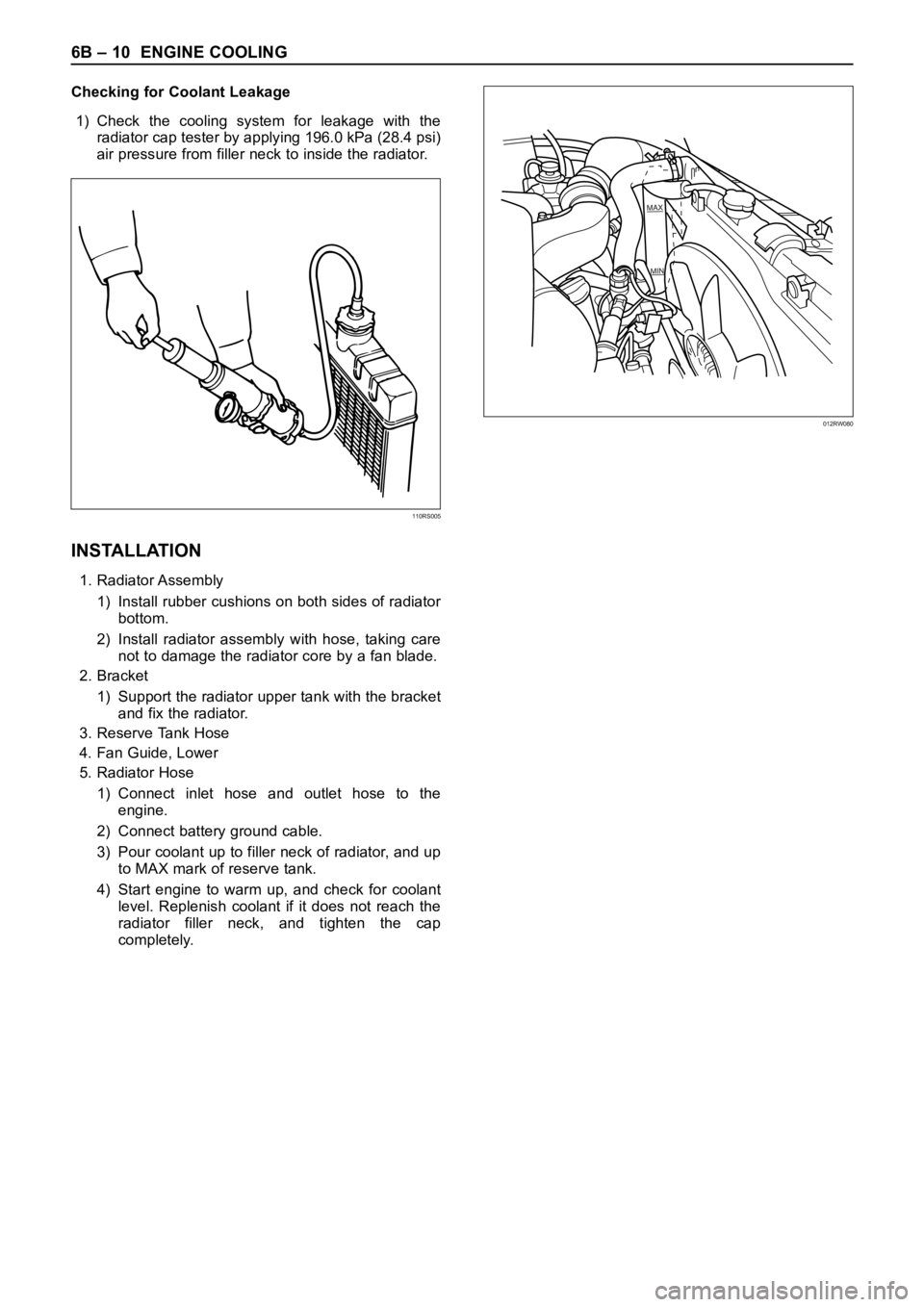
Checking for Coolant Leakage
1) Check the cooling system for leakage with the
radiator cap tester by applying 196.0 kPa (28.4 psi)
air pressure from filler neck to inside the radiator.
INSTALLATION
1. Radiator Assembly
1) Install rubber cushions on both sides of radiator
bottom.
2) Install radiator assembly with hose, taking care
not to damage the radiator core by a fan blade.
2. Bracket
1) Support the radiator upper tank with the bracket
and fix the radiator.
3. Reserve Tank Hose
4. Fan Guide, Lower
5. Radiator Hose
1) Connect inlet hose and outlet hose to the
engine.
2) Connect battery ground cable.
3) Pour coolant up to filler neck of radiator, and up
to MAX mark of reserve tank.
4) Start engine to warm up, and check for coolant
level. Replenish coolant if it does not reach the
radiator filler neck, and tighten the cap
completely.
110RS005
012RW080
Page 5380 of 6000
ENGINE COOLING 6B – 11
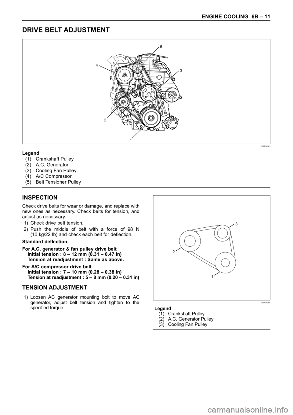
DRIVE BELT ADJUSTMENT
INSPECTION
Check drive belts for wear or damage, and replace with
new ones as necessary. Check belts for tension, and
adjust as necessary.
1) Check drive belt tension.
2) Push the middle of belt with a force of 98 N
(10 kg/22 lb) and check each belt for deflection.
Standard deflection:
For A.C. generator & fan pulley drive belt
Initial tension : 8 – 12 mm (0.31 – 0.47 in)
Tension at readjustment : Same as above.
For A/C compressor drive belt
Initial tension : 7 – 10 mm (0.28 – 0.38 in)
Tension at readjustment : 5 – 8 mm (0.20 – 0.31 in)
TENSION ADJUSTMENT
1) Loosen AC generator mounting bolt to move AC
generator, adjust belt tension and tighten to the
specified torque.
Legend
(1) Crankshaft Pulley
(2) A.C. Generator Pulley
(3) Cooling Fan Pulley
5
3
1 2 4
Legend
(1) Crankshaft Pulley
(2) A.C. Generator
(3) Cooling Fan Pulley
(4) A/C Compressor
(5) Belt Tensioner Pulley
012RW085
3
2
1
012RW084