change time OPEL FRONTERA 1998 Workshop Manual
[x] Cancel search | Manufacturer: OPEL, Model Year: 1998, Model line: FRONTERA, Model: OPEL FRONTERA 1998Pages: 6000, PDF Size: 97 MB
Page 281 of 6000

1. Perform oil return operation.
2. Discharge and recover the refrigerant and remove
the compressor.
3. Drain the compressor oil and measure the extracted
oil.
4. Check the compressor oil for contamination.
5. Adjust the oil level as required.
6. Evacuate, charge and perform the oil return
operation.
7. Check the system operation.
Contamination of Compressor Oil
Unlike engine oil, no cleaning agent is added to the
compressor oil. Even if the compressor runs for a long
period of time (approximately one season), the oil never
becomes contaminated as long as there is nothing
wrong with the compressor or its method of use.
Inspect the extracted oil for any of the following
conditions:
The capacity of the oil has increased.
The oil has changed to red.
Foreign substances, metal powder, etc., are present
in the oil.
If any of these conditions exists, the compressor
oil is contaminated. Whenever contaminated
compressor oil is discovered, the receiver/drier
must be replaced.
Oil Return Operation
There is close affinity between the oil and the
refrigerant. During normal operation, part of the oil
recirculates with the refrigerant in the system. When
checking the amount of oil in the system, or replacing
any component of the system, the compressor must be
run in advance for oil return operation. The procedure
is as follows:
1. Open all the doors and the engine hood.
2. Start the engine and air conditioning switch to "ON"
and set the fan control knob at its highest position.
3. Run the compressor for more than 20 minutes
between 800 and 1,000 rpm in order to operate the
system.
4. Stop the engine.
Replacement of Component Parts
When replacing the system component parts, supply
the following amount of oil to the component parts to be
installed.
Compressor Leak Testing (External and
Internal)
Bench-Check Procedure
1. Install test plate J-39893 on rear head of compressor.
2. Using Refrigerant Recovery System, attach center
hose of manifold gage set on charging station to a
refrigerant drum standing in an upright drum.
3. Connect charging station high and low pressure
lines to corresponding fittings on test plate J-39893.
Suction port (low-side) of compressor has large
internal opening. Discharge port (high-side) has
smaller internal opening into compressor and
deeper recess.
4. Open low pressure control, high pressure control
and refrigerant control on charging station to allow
refrigerant vapor to flow into compressor.
5. Using a leak detector, check for leaks at pressure
relief valve, rear head switch location, compressor
front and rear head seals, center cylinder seal,
through bolt head gaskets and compressor shaft
seal. After checking, shut off low pressure control
and high-pressure control on charging station.
6. If an external leak is present, perform the necessary
corrective measures and recheck for leaks to make
certain the leak has been connected.
7. Recover the refrigerant.
8. Disconnect both hoses from the test plate J-39893.
9. Add 90 ml (3 oz.) new PAG lubricant to the
compressor assembly. Rotate the complete
compressor assembly (not the crankshaft or drive
plate hub) slowly several turns to distribute oil to all
cylinder and piston areas.
10. Install a M9
1.25 threaded nut on the compressor
crankshaft if the drive plate and clutch assembly are
not installed.
11. Using a box-end wrench or socket and handle,
rotate the compressor crankshaft or clutch drive
plate on the crankshaft several turns to insure
piston assembly to cylinder wall lubrication.
12. Using Refrigerant Recovery System, connect the
charging station high-pressure line to the test plate
J-39893 high-side connector.
13. Using Refrigerant Recovery System, connect the
charging station low-pressure line to the low
pressure port of the test plate J-39893. Oil will drain
out of the compressor suction port if the compressor
is positioned with the suction port downward. (Component parts to be (Amount of Oil)
installed)
Evaporator 50 cc (1.7 fl. oz.)
Condenser 30 cc (1.0 fl. oz.)
Receiver/dryer 30 cc (1.0 fl. oz.)
Refrigerant line (one 10 cc (0.3 fl. oz.)
piece)
(Amount of oil drained (Charging amount of oil
from used compressor) to new compressor)
more than 90 cc same as drained amount
(3.0 fl.oz)
less than 90 cc (3.0 fl.oz) 90 cc (3.0 fl.oz)
Page 541 of 6000
4B1–8
DRIVE LINE CONTROL SYSTEM (SHIFT ON THE FLY)
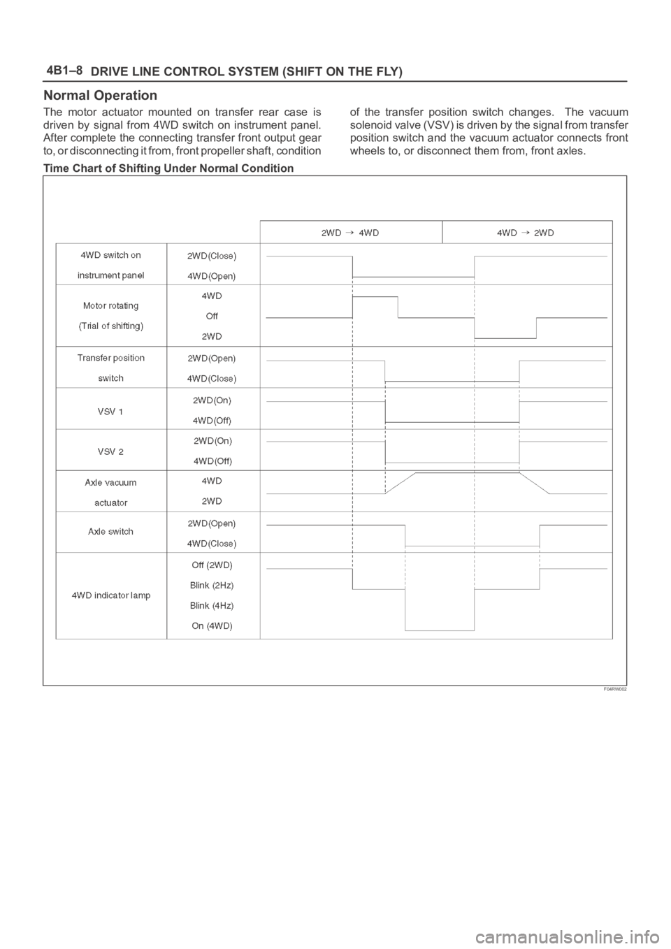
Normal Operation
The motor actuator mounted on transfer rear case is
driven by signal from 4WD switch on instrument panel.
After complete the connecting transfer front output gear
to, or disconnecting it from, front propeller shaft, conditionof the transfer position switch changes. The vacuum
solenoid valve (VSV) is driven by the signal from transfer
position switch and the vacuum actuator connects front
wheels to, or disconnect them from, front axles.
Time Chart of Shifting Under Normal Condition
F04RW002
Page 542 of 6000
4B1–9 DRIVE LINE CONTROL SYSTEM (SHIFT ON THE FLY)
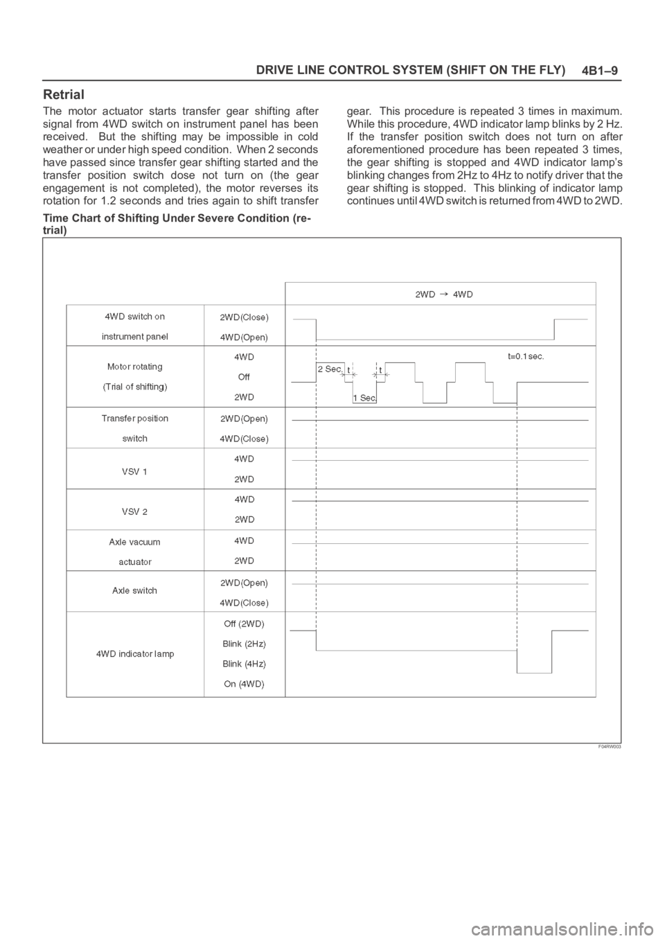
Retrial
The motor actuator starts transfer gear shifting after
signal from 4WD switch on instrument panel has been
received. But the shifting may be impossible in cold
weather or under high speed condition. When 2 seconds
have passed since transfer gear shifting started and the
transfer position switch dose not turn on (the gear
engagement is not completed), the motor reverses its
rotation for 1.2 seconds and tries again to shift transfergear. This procedure is repeated 3 times in maximum.
While this procedure, 4WD indicator lamp blinks by 2 Hz.
If the transfer position switch does not turn on after
aforementioned procedure has been repeated 3 times,
the gear shifting is stopped and 4WD indicator lamp’s
blinking changes from 2Hz to 4Hz to notify driver that the
gear shifting is stopped. This blinking of indicator lamp
continues until 4WD switch is returned from 4WD to 2WD.
Time Chart of Shifting Under Severe Condition (re-
trial)
F04RW003
Page 543 of 6000
4B1–10
DRIVE LINE CONTROL SYSTEM (SHIFT ON THE FLY)
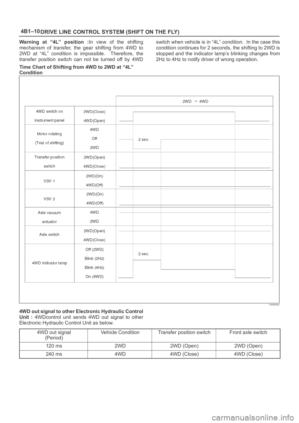
Warning at “4L” position :In view of the shifting
mechanism of transfer, the gear shifting from 4WD to
2WD at “4L” condition is impossible. Therefore, the
transfer position switch can not be turned off by 4WDswitch when vehicle is in “4L” condition. In the case this
condition continues for 2 seconds, the shifting to 2WD is
stopped and the indicator lamp’s blinking changes from
2Hz to 4Hz to notify driver of wrong operation.
Time Chart of Shifting from 4WD to 2WD at “4L”
Condition
F04RW005
4WD out signal to other Electronic Hydraulic Control
Unit : 4WDcontrol unit sends 4WD out signal to other
Electronic Hydraulic Control Unit as below.
4WD out signal
(Period)
Vehicle ConditionTransfer position switchFront axle switch
120 ms2WD2WD (Open)2WD (Open)
240 ms4WD4WD (Close)4WD (Close)
Page 544 of 6000
4B1–11 DRIVE LINE CONTROL SYSTEM (SHIFT ON THE FLY)
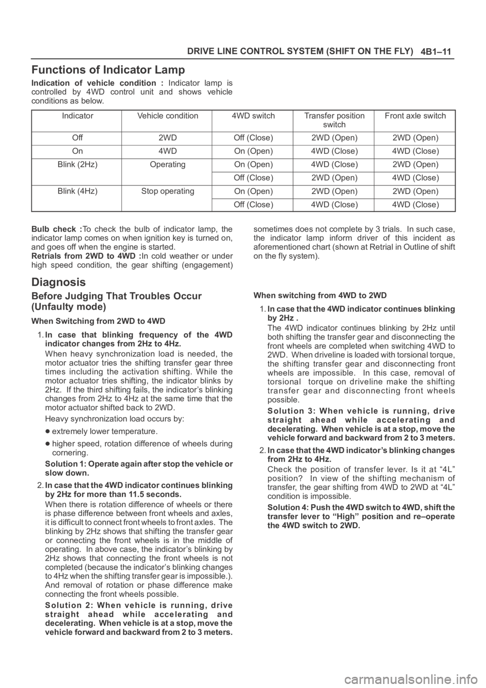
Functions of Indicator Lamp
Indication of vehicle condition : Indicator lamp is
controlled by 4WD control unit and shows vehicle
conditions as below.
Indicator
Vehicle condition4WD switchTransfer position
switchFront axle switch
Off2WDOff (Close)2WD (Open)2WD (Open)
On4WDOn (Open)4WD (Close)4WD (Close)
Blink (2Hz)OperatingOn (Open)4WD (Close)2WD (Open)
Off (Close)2WD (Open)4WD (Close)
Blink (4Hz)Stop operatingOn (Open)2WD (Open)2WD (Open)
Off (Close)4WD (Close)4WD (Close)
Bulb check :To check the bulb of indicator lamp, the
indicator lamp comes on when ignition key is turned on,
and goes off when the engine is started.
Retrials from 2WD to 4WD :In cold weather or under
high speed condition, the gear shifting (engagement)sometimes does not complete by 3 trials. In such case,
the indicator lamp inform driver of this incident as
aforementioned chart (shown at Retrial in Outline of shift
on the fly system).
Diagnosis
Before Judging That Troubles Occur
(Unfaulty mode)
When Switching from 2WD to 4WD
1.In case that blinking frequency of the 4WD
indicator changes from 2Hz to 4Hz.
When heavy synchronization load is needed, the
motor actuator tries the shifting transfer gear three
times including the activation shifting. While the
motor actuator tries shifting, the indicator blinks by
2Hz. If the third shifting fails, the indicator’s blinking
changes from 2Hz to 4Hz at the same time that the
motor actuator shifted back to 2WD.
Heavy synchronization load occurs by:
extremely lower temperature.
higher speed, rotation difference of wheels during
cornering.
Solution 1: Operate again after stop the vehicle or
slow down.
2.In case that the 4WD indicator continues blinking
by 2Hz for more than 11.5 seconds.
When there is rotation difference of wheels or there
is phase difference between front wheels and axles,
it is difficult to connect front wheels to front axles. The
blinking by 2Hz shows that shifting the transfer gear
or connecting the front wheels is in the middle of
operating. In above case, the indicator’s blinking by
2Hz shows that connecting the front wheels is not
completed (because the indicator’s blinking changes
to 4Hz when the shifting transfer gear is impossible.).
And removal of rotation or phase difference make
connecting the front wheels possible.
Solution 2: When vehicle is running, drive
straight ahead while accelerating and
decelerating. When vehicle is at a stop, move the
vehicle forward and backward from 2 to 3 meters.When switching from 4WD to 2WD
1.In case that the 4WD indicator continues blinking
by 2Hz .
The 4WD indicator continues blinking by 2Hz until
both shifting the transfer gear and disconnecting the
front wheels are completed when switching 4WD to
2WD. When driveline is loaded with torsional torque,
the shifting transfer gear and disconnecting front
wheels are impossible. In this case, removal of
torsional torque on driveline make the shifting
transfer gear and disconnecting front wheels
possible.
Solution 3: When vehicle is running, drive
straight ahead while accelerating and
decelerating. When vehicle is at a stop, move the
vehicle forward and backward from 2 to 3 meters.
2.In case that the 4WD indicator’s blinking changes
from 2Hz to 4Hz.
Check the position of transfer lever. Is it at “4L”
position? In view of the shifting mechanism of
transfer, the gear shifting from 4WD to 2WD at “4L”
condition is impossible.
Solution 4: Push the 4WD switch to 4WD, shift the
transfer lever to “High” position and re–operate
the 4WD switch to 2WD.
Page 585 of 6000
DRIVE LINE CONTROL SYSTEM (TOD) 4B2–14
How to Clear The Trouble Code
The trouble codes saved to the control unit can be deleted
by the following procedure if the starter switch is being in
the OFF position.
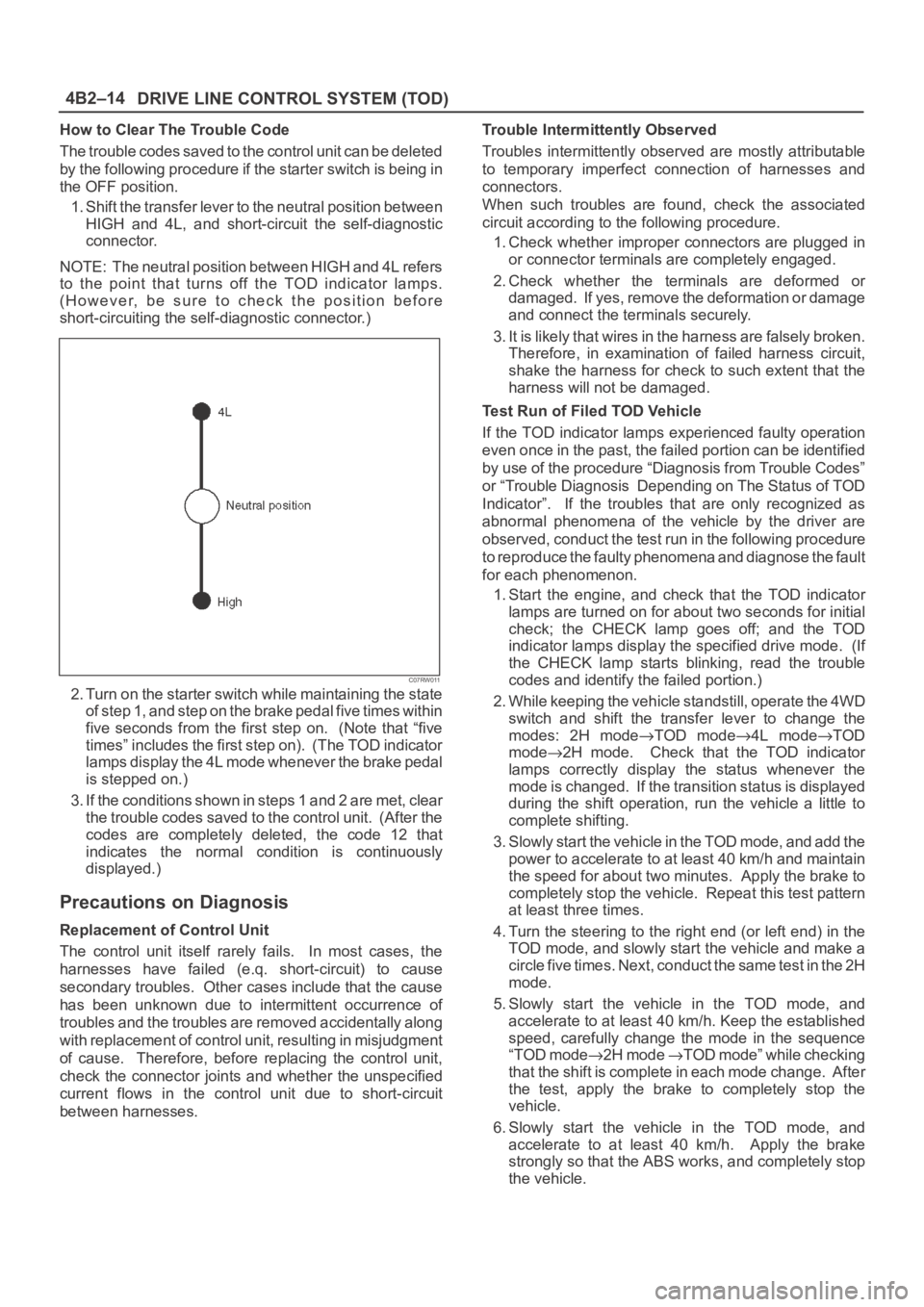
1. Shift the transfer lever to the neutral position between
HIGH and 4L, and short-circuit the self-diagnostic
connector.
NOTE: The neutral position between HIGH and 4L refers
to the point that turns off the TOD indicator lamps.
(However, be sure to check the position before
short-circuiting the self-diagnostic connector.)
C07RW011
2. Turn on the starter switch while maintaining the state
of step 1, and step on the brake pedal five times within
five seconds from the first step on. (Note that “five
times” includes the first step on). (The TOD indicator
lamps display the 4L mode whenever the brake pedal
is stepped on.)
3. If the conditions shown in steps 1 and 2 are met, clear
the trouble codes saved to the control unit. (After the
codes are completely deleted, the code 12 that
indicates the normal condition is continuously
displayed.)
Precautions on Diagnosis
Replacement of Control Unit
The control unit itself rarely fails. In most cases, the
harnesses have failed (e.q. short-circuit) to cause
secondary troubles. Other cases include that the cause
has been unknown due to intermittent occurrence of
troubles and the troubles are removed accidentally along
with replacement of control unit, resulting in misjudgment
of cause. Therefore, before replacing the control unit,
check the connector joints and whether the unspecified
current flows in the control unit due to short-circuit
between harnesses.Trouble Intermittently Observed
Troubles intermittently observed are mostly attributable
to temporary imperfect connection of harnesses and
connectors.
When such troubles are found, check the associated
circuit according to the following procedure.
1. Check whether improper connectors are plugged in
or connector terminals are completely engaged.
2. Check whether the terminals are deformed or
damaged. If yes, remove the deformation or damage
and connect the terminals securely.
3. It is likely that wires in the harness are falsely broken.
Therefore, in examination of failed harness circuit,
shake the harness for check to such extent that the
harness will not be damaged.
Test Run of Filed TOD Vehicle
If the TOD indicator lamps experienced faulty operation
even once in the past, the failed portion can be identified
by use of the procedure “Diagnosis from Trouble Codes”
or “Trouble Diagnosis Depending on The Status of TOD
Indicator”. If the troubles that are only recognized as
abnormal phenomena of the vehicle by the driver are
observed, conduct the test run in the following procedure
to reproduce the faulty phenomena and diagnose the fault
for each phenomenon.
1. Start the engine, and check that the TOD indicator
lamps are turned on for about two seconds for initial
check; the CHECK lamp goes off; and the TOD
indicator lamps display the specified drive mode. (If
the CHECK lamp starts blinking, read the trouble
codes and identify the failed portion.)
2. While keeping the vehicle standstill, operate the 4WD
switch and shift the transfer lever to change the
modes: 2H mode
TOD mode4L modeTOD
mode
2H mode. Check that the TOD indicator
lamps correctly display the status whenever the
mode is changed. If the transition status is displayed
during the shift operation, run the vehicle a little to
complete shifting.
3. Slowly start the vehicle in the TOD mode, and add the
power to accelerate to at least 40 km/h and maintain
the speed for about two minutes. Apply the brake to
completely stop the vehicle. Repeat this test pattern
at least three times.
4. Turn the steering to the right end (or left end) in the
TOD mode, and slowly start the vehicle and make a
c i r c l e f i v e t i m e s . N e x t , c o n d u c t t h e s a m e t e s t i n t h e 2 H
mode.
5. Slowly start the vehicle in the TOD mode, and
accelerate to at least 40 km/h. Keep the established
speed, carefully change the mode in the sequence
“TOD mode
2H mode TOD mode” while checking
that the shift is complete in each mode change. After
the test, apply the brake to completely stop the
vehicle.
6. Slowly start the vehicle in the TOD mode, and
accelerate to at least 40 km/h. Apply the brake
strongly so that the ABS works, and completely stop
the vehicle.
Page 597 of 6000
DRIVE LINE CONTROL SYSTEM (TOD) 4B2–26
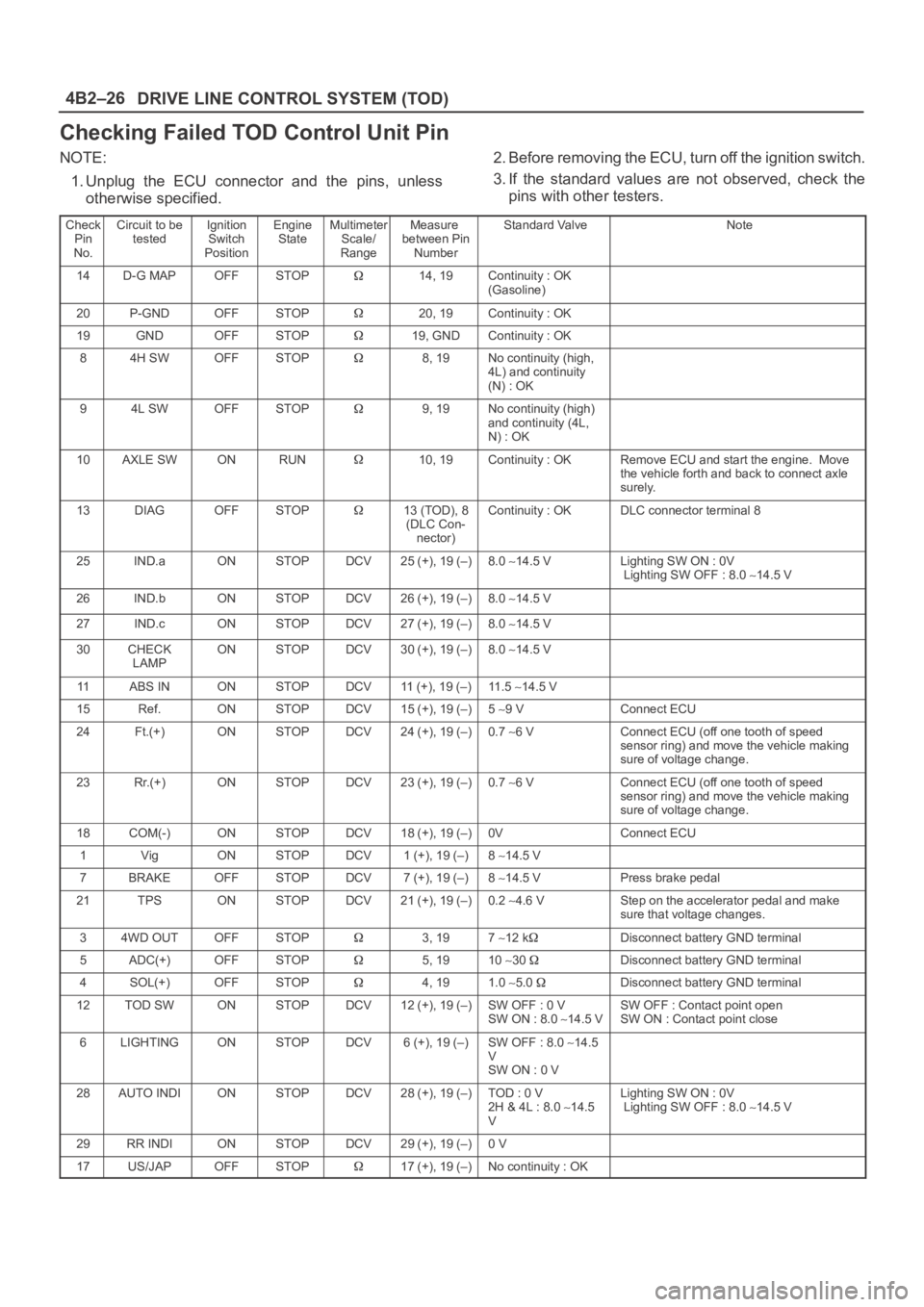
Checking Failed TOD Control Unit Pin
NOTE:
1. Unplug the ECU connector and the pins, unless
otherwise specified.2. Before removing the ECU, turn off the ignition switch.
3. If the standard values are not observed, check the
pins with other testers.
Check
Pin
No.Circuit to be
testedIgnition
Switch
PositionEngine
StateMultimeter
Scale/
RangeMeasure
between Pin
NumberStandard ValveNote
14D-G MAPOFFSTOP14, 19Continuity : OK
(Gasoline)
20P-GNDOFFSTOP20, 19Continuity : OK
19GNDOFFSTOP19, GNDContinuity : OK
84H SWOFFSTOP8, 19No continuity (high,
4L) and continuity
(N) : OK
94L SWOFFSTOP9, 19No continuity (high)
and continuity (4L,
N) : OK
10AXLE SWONRUN10, 19Continuity : OKRemove ECU and start the engine. Move
the vehicle forth and back to connect axle
surely.
13DIAGOFFSTOP13 (TOD), 8
(DLC Con-
nector)Continuity : OKDLC connector terminal 8
25IND.aONSTOPDCV25 (+), 19 (–)8.0 14.5 VLighting SW ON : 0V
Lighting SW OFF : 8.0 14.5 V
26IND.bONSTOPDCV26 (+), 19 (–)8.0 14.5 V
27IND.cONSTOPDCV27 (+), 19 (–)8.0 14.5 V
30CHECK
LAMPONSTOPDCV30 (+), 19 (–)8.0 14.5 V
11ABS INONSTOPDCV11 (+), 19 (–)11 . 5 14.5 V
15Ref.ONSTOPDCV15 (+), 19 (–)5 9 VConnect ECU
24Ft.(+)ONSTOPDCV24 (+), 19 (–)0.7 6 VConnect ECU (off one tooth of speed
sensor ring) and move the vehicle making
sure of voltage change.
23Rr.(+)ONSTOPDCV23 (+), 19 (–)0.7 6 VConnect ECU (off one tooth of speed
sensor ring) and move the vehicle making
sure of voltage change.
18COM(-)ONSTOPDCV18 (+), 19 (–)0VConnect ECU
1VigONSTOPDCV1 (+), 19 (–)8 14.5 V
7BRAKEOFFSTOPDCV7 (+), 19 (–)8 14.5 VPress brake pedal
21TPSONSTOPDCV21 (+), 19 (–)0.2 4.6 VStep on the accelerator pedal and make
sure that voltage changes.
34WD OUTOFFSTOP3, 197 12 kDisconnect battery GND terminal
5ADC(+)OFFSTOP5, 1910 30 Disconnect battery GND terminal
4SOL(+)OFFSTOP4, 191.0 5.0 Disconnect battery GND terminal
12TOD SWONSTOPDCV12 (+), 19 (–)SW OFF : 0 V
SW ON : 8.0 14.5 VSW OFF : Contact point open
SW ON : Contact point close
6LIGHTINGONSTOPDCV6 (+), 19 (–)SW OFF : 8.0 14.5
V
SW ON : 0 V
28AUTO INDIONSTOPDCV28 (+), 19 (–)TOD : 0 V
2H & 4L : 8.0 14.5
VLighting SW ON : 0V
Lighting SW OFF : 8.0 14.5 V
29RR INDIONSTOPDCV29 (+), 19 (–)0 V
17US/JAPOFFSTOP17 (+), 19 (–)No continuity : OK
Page 968 of 6000

6A–12
ENGINE MECHANICAL
ConditionPossible causeCorrection
Noise from connecting rods or from
connecting rod bearings
(Faulty connecting rods orBearing or crankshaft pin wornReplace connecting rod bearings
and crankshaft or regrind crankshaft
pin and install the undersize bearing
yg
connecting rod bearings usually
make an abnormal noise slightly
higher than the crank bearing noise,
which becomes more evident when
Crankpin out of roundReplace connecting rod bearings
and crankshaft or regrind crankshaft
pin and install the undersize bearing
which becomes more evident when
engine is accelerated)Connecting rod bentCorrect or replaceg)
Connecting rod bearing seizedReplace connecting rod bearings
and crankshaft or regrind crankshaft
pin and install the undersize bearing
Troubleshooting Procedure
Abnormal noise stops when the spark plug on the cylinder
with defective part is shorted out.
Condition
Possible causeCorrection
Piston and cylinder noise
(Faulty piston or cylinder usually
kbidhil
Piston clearance increased due to
cylinder wearReplace piston and cylinder body
makes a combined mechanical
thumping noise which increasesPiston seizedReplace piston and cylinder bodyg
when engine is suddenly accelerated
but diminishes
gradually as thePiston ring brokenReplace piston and cylinder bodybut diminishes gradually as the
engine warms up)Piston defectiveReplace pistons and others
Troubleshooting Procedure
Short out each spark plug and listen for change in engine
noise.
Condition
Possible causeCorrection
Piston pin noise
(Piston makes noise each time it
goes up and down)Piston pin or piston pin hole wornReplace piston, piston pin and
connecting rod assy
Troubleshooting Procedure
The slapping sound stops when spark plug on bad
cylinder is shorted out.
Condition
Possible causeCorrection
Timing belt noiseTiming belt tension is incorrectReplace pusher or adjust the tension
pulley or replace timing belt
Tensioner bearing defectiveReplace
Timing belt defectiveReplace
Timing pulley defectiveReplace
Timing belt comes in contact with
timing coverReplace timing belt and timing cover
Valve noiseValve clearance incorrectReplace adjusting shim
Valve and valve guide seizedReplace valve and valve guide
Valve spring broken or weakenedReplace
Valve seat off–positionedCorrect
Camshaft worn outReplace
Crankshaft noiseCrankshaft end play excessive
(noise occurs when clutch is
engaged)Replace thrust bearing
Page 1115 of 6000
6D3–24STARTING AND CHARGING SYSTEM
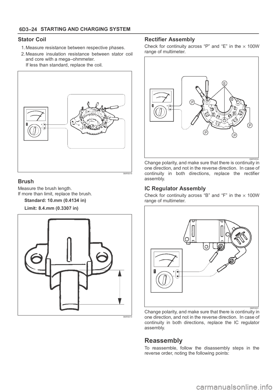
Stator Coil
1. Measure resistance between respective phases.
2. Measure insulation resistance between stator coil
and core with a mega–ohmmeter.
If less than standard, replace the coil.
066RS018
Brush
Measure the brush length.
If more than limit, replace the brush.
Standard: 10.mm (0.4134 in)
Limit: 8.4.mm (0.3307 in)
066RS019
Rectifier Assembly
Check for continuity across “P” and “E” in the 100W
range of multimeter.
066RW002Change polarity, and make sure that there is continuity in
one direction, and not in the reverse direction. In case of
continuity in both directions, replace the rectifier
assembly.
IC Regulator Assembly
Check for continuity across “B” and “F” in the 100W
range of multimeter.
066RS021Change polarity, and make sure that there is continuity in
one direction, and not in the reverse direction. In case of
continuity in both directions, replace the IC regulator
assembly.
Reassembly
To reassemble, follow the disassembly steps in the
reverse order, noting the following points:
Page 1155 of 6000
6E–38
ENGINE DRIVEABILITY AND EMISSIONS
General Service Information
OBD Serviceablity Issues
The list of non-vehicle faults that could affect the
performance of the OBD system has been compiled.
These non-vehicle faults vary from environmental
conditions to the quality of fuel used.
The illumination of the MIL (“Check Engine” lamp) due to
a non-vehicle fault could lead to misdiagnosis of the
vehicle, increased warranty expense and customer
dissatisfaction. The following list of non-vehicle faults
does not include every possible fault and may not apply
equally to all product lines.
Fuel Quality
Using fuel with the wrong octane rating for your vehicle
may cause driveability problems. Many of the major fuel
companies advertise that using “premium” gasoline will
improve the performance of your vehicle. Most premium
fuels use alcohol to increase the octane rating of the fuel.
Although alcohol-enhanced fuels may raise the octane
rating, the fuel’s ability to turn into vapor in cold
temperatures deteriorates. This may affect the starting
ability and cold driveability of the engine.
Low fuel levels can lead to fuel starvation, lean engine
operation, and eventually engine misfire.
Non-OEM Parts
All of the OBD diagnostics have been calibrated to run
with OEM parts. Something as simple as a
high-performance exhaust system that affects exhaust
system back pressure could potentially interfere with the
operation of the EGR valve and thereby turn on the MIL
(“Check Engine” lamp). Small leaks in the exhaust
system near the post catalyst oxygen sensor can also
cause the MIL (“Check Engine” lamp) to turn on.
Aftermarket electronics, such as cellular phones,
stereos, and anti-theft devices, may radiate EMI into the
control system if they are improperly installed. This may
cause a false sensor reading and turn on the MIL (“Check
Engine” lamp).
Environment
Temporary environmental conditions, such as localized
flooding, will have an effect on the vehicle ignition system.
If the ignition system is rain-soaked, it can temporarily
cause engine misfire and turn on the MIL (“Check Engine”
lamp).
Poor Vehicle Maintenance
The sensitivity of OBD diagnostics will cause the MIL
(“Check Engine” lamp) to turn on if the vehicle is not
maintained properly. Restricted air filters, fuel filters, and
crankcase deposits due to lack of oil changes or improper
oil viscosity can trigger actual vehicle faults that were not
previously monitored prior to OBD. Poor vehicle
maintenance can not be classified as a “non-vehicle
fault”, but with the sensitivity of OBD diagnostics, vehicle
maintenance schedules must be more closely followed.Related System Faults
Many of the OBD system diagnostics will not run if the
PCM detects a fault on a related system or component.
One example would be that if the PCM detected a Misfire
fault, the diagnostics on the catalytic converter would be
suspended until Misfire fault was repaired. If the Misfire
fault was severe enough, the catalytic converter could be
damaged due to overheating and would never set a
Catalyst DTC until the Misfire fault was repaired and the
Catalyst diagnostic was allowed to run to completion. If
this happens, the customer may have to make two trips to
the dealership in order to repair the vehicle.
Maintenance Schedule
Refer to the Maintenance Schedule.
Visual / Physical Engine Compartment
Inspection
Perform a careful visual and physical engine
compartment inspection when performing any diagnostic
procedure or diagnosing the cause of an emission test
failure. This can often lead to repairing a problem without
further steps. Use the following guidelines when
performing a visual/physical inspection:
Inspect all vacuum hoses for punches, cuts,
disconnects, and correct routing.
Inspect hoses that are difficult to see behind other
components.
Inspect all wires in the engine compartment for proper
connections, burned or chafed spots, pinched wires,
contact with sharp edges or contact with hot exhaust
manifolds or pipes.
Basic Knowledge of Tools Required
NOTE: Lack of basic knowledge of this powertrain when
performing diagnostic procedures could result in an
incorrect diagnosis or damage to powertrain
components. Do not attempt to diagnose a powertrain
problem without this basic knowledge.
A basic understanding of hand tools is necessary to effec-
tively use this section of the Service Manual.
Serial Data Communications
Class II Serial Data Communications
This vehicle utilizes the “Class II” communication system.
Each bit of information can have one of two lengths: long
or short. This allows vehicle wiring to be reduced by
transmitting and receiving multiple signals over a single
wire. The messages carried on Class II data streams are
also prioritized. If two messages attempt to establish
communications on the data line at the same time, only
the message with higher priority will continue. The device
with the lower priority message must wait. The most
significant result of this regulation is that it provides Tech 2
manufacturers with the capability to access data from any
make or model vehicle that is sold.