engine oil OPEL FRONTERA 1998 Workshop Manual
[x] Cancel search | Manufacturer: OPEL, Model Year: 1998, Model line: FRONTERA, Model: OPEL FRONTERA 1998Pages: 6000, PDF Size: 97 MB
Page 281 of 6000

1. Perform oil return operation.
2. Discharge and recover the refrigerant and remove
the compressor.
3. Drain the compressor oil and measure the extracted
oil.
4. Check the compressor oil for contamination.
5. Adjust the oil level as required.
6. Evacuate, charge and perform the oil return
operation.
7. Check the system operation.
Contamination of Compressor Oil
Unlike engine oil, no cleaning agent is added to the
compressor oil. Even if the compressor runs for a long
period of time (approximately one season), the oil never
becomes contaminated as long as there is nothing
wrong with the compressor or its method of use.
Inspect the extracted oil for any of the following
conditions:
The capacity of the oil has increased.
The oil has changed to red.
Foreign substances, metal powder, etc., are present
in the oil.
If any of these conditions exists, the compressor
oil is contaminated. Whenever contaminated
compressor oil is discovered, the receiver/drier
must be replaced.
Oil Return Operation
There is close affinity between the oil and the
refrigerant. During normal operation, part of the oil
recirculates with the refrigerant in the system. When
checking the amount of oil in the system, or replacing
any component of the system, the compressor must be
run in advance for oil return operation. The procedure
is as follows:
1. Open all the doors and the engine hood.
2. Start the engine and air conditioning switch to "ON"
and set the fan control knob at its highest position.
3. Run the compressor for more than 20 minutes
between 800 and 1,000 rpm in order to operate the
system.
4. Stop the engine.
Replacement of Component Parts
When replacing the system component parts, supply
the following amount of oil to the component parts to be
installed.
Compressor Leak Testing (External and
Internal)
Bench-Check Procedure
1. Install test plate J-39893 on rear head of compressor.
2. Using Refrigerant Recovery System, attach center
hose of manifold gage set on charging station to a
refrigerant drum standing in an upright drum.
3. Connect charging station high and low pressure
lines to corresponding fittings on test plate J-39893.
Suction port (low-side) of compressor has large
internal opening. Discharge port (high-side) has
smaller internal opening into compressor and
deeper recess.
4. Open low pressure control, high pressure control
and refrigerant control on charging station to allow
refrigerant vapor to flow into compressor.
5. Using a leak detector, check for leaks at pressure
relief valve, rear head switch location, compressor
front and rear head seals, center cylinder seal,
through bolt head gaskets and compressor shaft
seal. After checking, shut off low pressure control
and high-pressure control on charging station.
6. If an external leak is present, perform the necessary
corrective measures and recheck for leaks to make
certain the leak has been connected.
7. Recover the refrigerant.
8. Disconnect both hoses from the test plate J-39893.
9. Add 90 ml (3 oz.) new PAG lubricant to the
compressor assembly. Rotate the complete
compressor assembly (not the crankshaft or drive
plate hub) slowly several turns to distribute oil to all
cylinder and piston areas.
10. Install a M9
1.25 threaded nut on the compressor
crankshaft if the drive plate and clutch assembly are
not installed.
11. Using a box-end wrench or socket and handle,
rotate the compressor crankshaft or clutch drive
plate on the crankshaft several turns to insure
piston assembly to cylinder wall lubrication.
12. Using Refrigerant Recovery System, connect the
charging station high-pressure line to the test plate
J-39893 high-side connector.
13. Using Refrigerant Recovery System, connect the
charging station low-pressure line to the low
pressure port of the test plate J-39893. Oil will drain
out of the compressor suction port if the compressor
is positioned with the suction port downward. (Component parts to be (Amount of Oil)
installed)
Evaporator 50 cc (1.7 fl. oz.)
Condenser 30 cc (1.0 fl. oz.)
Receiver/dryer 30 cc (1.0 fl. oz.)
Refrigerant line (one 10 cc (0.3 fl. oz.)
piece)
(Amount of oil drained (Charging amount of oil
from used compressor) to new compressor)
more than 90 cc same as drained amount
(3.0 fl.oz)
less than 90 cc (3.0 fl.oz) 90 cc (3.0 fl.oz)
Page 573 of 6000
DRIVE LINE CONTROL SYSTEM (TOD) 4B2–2
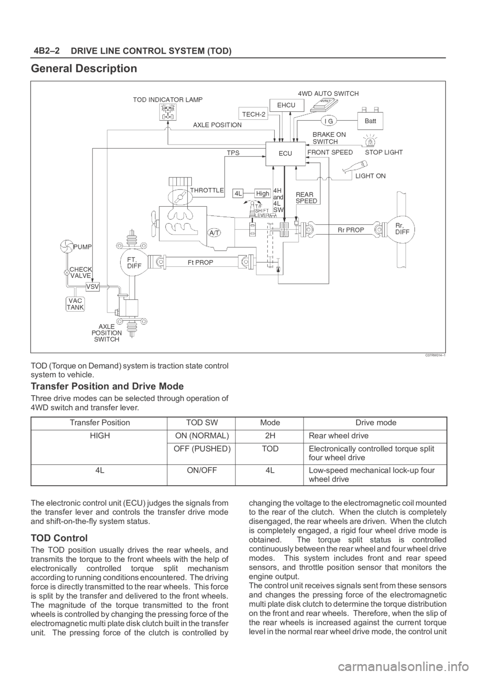
General Description
C07RW014–1
TOD (Torque on Demand) system is traction state control
system to vehicle.
Transfer Position and Drive Mode
Three drive modes can be selected through operation of
4WD switch and transfer lever.
Transfer Position
TOD SWModeDrive mode
HIGHON (NORMAL)2HRear wheel drive
OFF (PUSHED)TODElectronically controlled torque split
four wheel drive
4LON/OFF4LLow-speed mechanical lock-up four
wheel drive
The electronic control unit (ECU) judges the signals from
the transfer lever and controls the transfer drive mode
and shift-on-the-fly system status.
TOD Control
The TOD position usually drives the rear wheels, and
transmits the torque to the front wheels with the help of
electronically controlled torque split mechanism
according to running conditions encountered. The driving
force is directly transmitted to the rear wheels. This force
is split by the transfer and delivered to the front wheels.
The magnitude of the torque transmitted to the front
wheels is controlled by changing the pressing force of the
electromagnetic multi plate disk clutch built in the transfer
unit. The pressing force of the clutch is controlled bychanging the voltage to the electromagnetic coil mounted
to the rear of the clutch. When the clutch is completely
disengaged, the rear wheels are driven. When the clutch
is completely engaged, a rigid four wheel drive mode is
obtained. The torque split status is controlled
continuously between the rear wheel and four wheel drive
modes. This system includes front and rear speed
sensors, and throttle position sensor that monitors the
engine output.
The control unit receives signals sent from these sensors
and changes the pressing force of the electromagnetic
multi plate disk clutch to determine the torque distribution
on the front and rear wheels. Therefore, when the slip of
the rear wheels is increased against the current torque
level in the normal rear wheel drive mode, the control unit
Page 601 of 6000
DRIVE LINE CONTROL SYSTEM (TOD) 4B2–30
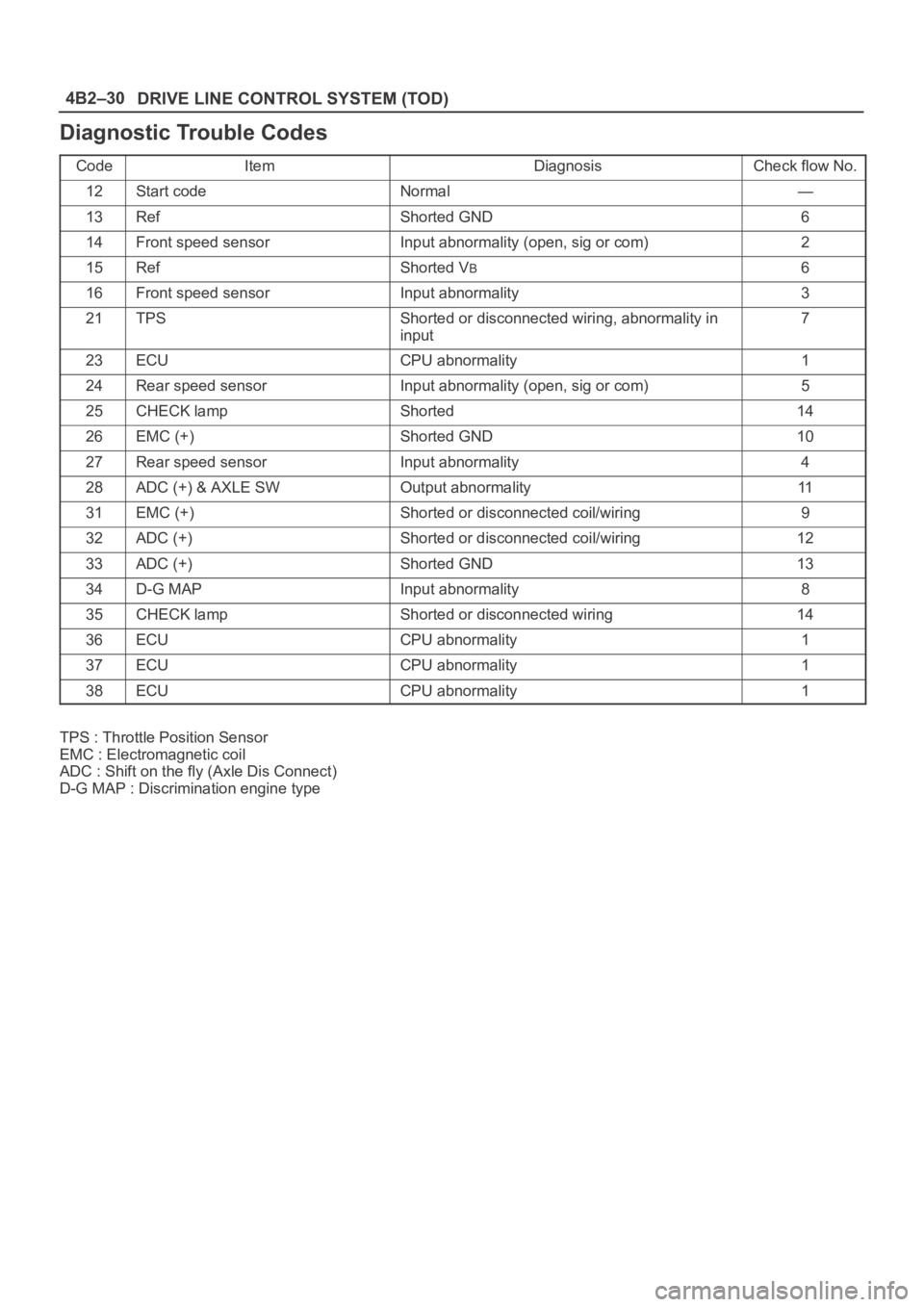
Diagnostic Trouble Codes
CodeItemDiagnosisCheck flow No.
12Start codeNormal—
13RefShorted GND6
14Front speed sensorInput abnormality (open, sig or com)2
15RefShorted VB6
16Front speed sensorInput abnormality3
21TPSShorted or disconnected wiring, abnormality in
input7
23ECUCPU abnormality1
24Rear speed sensorInput abnormality (open, sig or com)5
25CHECK lampShorted14
26EMC (+)Shorted GND10
27Rear speed sensorInput abnormality4
28ADC (+) & AXLE SWOutput abnormality11
31EMC (+)Shorted or disconnected coil/wiring9
32ADC (+)Shorted or disconnected coil/wiring12
33ADC (+)Shorted GND13
34D-G MAPInput abnormality8
35CHECK lampShorted or disconnected wiring14
36ECUCPU abnormality1
37ECUCPU abnormality1
38ECUCPU abnormality1
TPS : Throttle Position Sensor
EMC : Electromagnetic coil
ADC : Shift on the fly (Axle Dis Connect)
D-G MAP : Discrimination engine type
Page 618 of 6000
4B2–47 DRIVE LINE CONTROL SYSTEM (TOD)
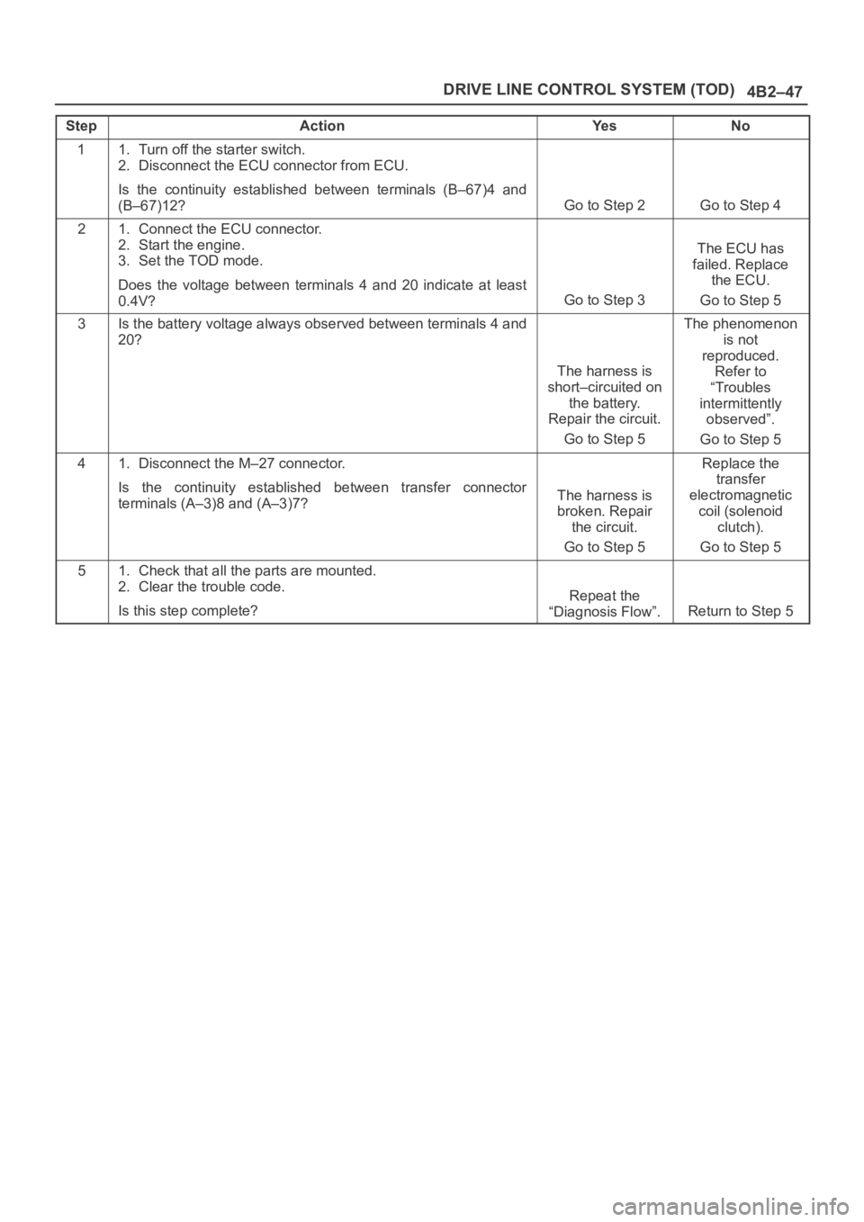
StepActionYe sNo
11. Turn off the starter switch.
2. Disconnect the ECU connector from ECU.
Is the continuity established between terminals (B–67)4 and
(B–67)12?
Go to Step 2Go to Step 4
21. Connect the ECU connector.
2. Start the engine.
3. Set the TOD mode.
Does the voltage between terminals 4 and 20 indicate at least
0.4V?
Go to Step 3
The ECU has
failed. Replace
the ECU.
Go to Step 5
3Is the battery voltage always observed between terminals 4 and
20?
The harness is
short–circuited on
the battery.
Repair the circuit.
Go to Step 5
The phenomenon
is not
reproduced.
Refer to
“Troubles
intermittently
observed”.
Go to Step 5
41. Disconnect the M–27 connector.
Is the continuity established between transfer connector
terminals (A–3)8 and (A–3)7?
The harness is
broken. Repair
the circuit.
Go to Step 5
Replace the
transfer
electromagnetic
coil (solenoid
clutch).
Go to Step 5
51. Check that all the parts are mounted.
2. Clear the trouble code.
Is this step complete?
Repeat the
“Diagnosis Flow”.
Return to Step 5
Page 620 of 6000
4B2–49 DRIVE LINE CONTROL SYSTEM (TOD)
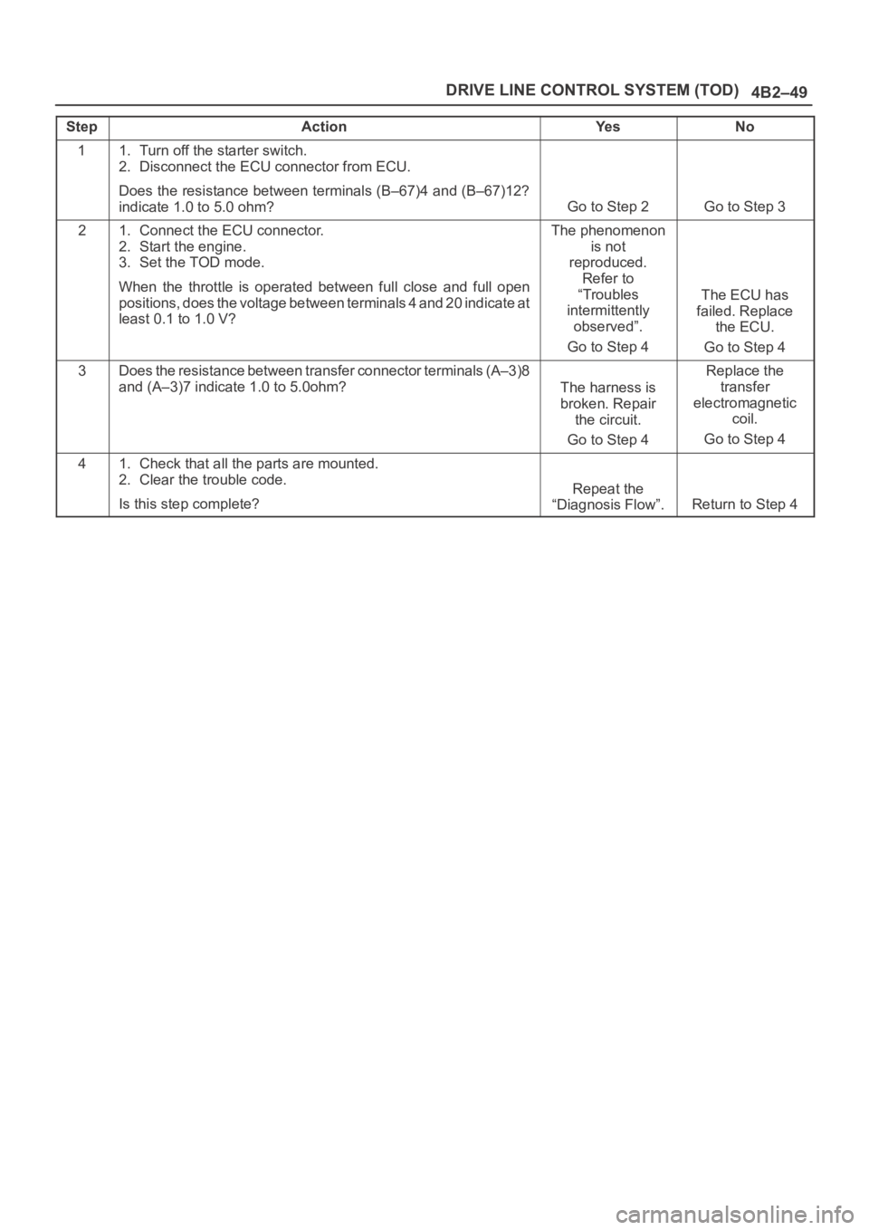
StepActionYe sNo
11. Turn off the starter switch.
2. Disconnect the ECU connector from ECU.
Does the resistance between terminals (B–67)4 and (B–67)12?
indicate 1.0 to 5.0 ohm?
Go to Step 2Go to Step 3
21. Connect the ECU connector.
2. Start the engine.
3. Set the TOD mode.
When the throttle is operated between full close and full open
positions, does the voltage between terminals 4 and 20 indicate a t
least 0.1 to 1.0 V?The phenomenon
is not
reproduced.
Refer to
“Troubles
intermittently
observed”.
Go to Step 4
The ECU has
failed. Replace
the ECU.
Go to Step 4
3Does the resistance between transfer connector terminals (A–3)8
and (A–3)7 indicate 1.0 to 5.0ohm?
The harness is
broken. Repair
the circuit.
Go to Step 4
Replace the
transfer
electromagnetic
coil.
Go to Step 4
41. Check that all the parts are mounted.
2. Clear the trouble code.
Is this step complete?
Repeat the
“Diagnosis Flow”.
Return to Step 4
Page 659 of 6000
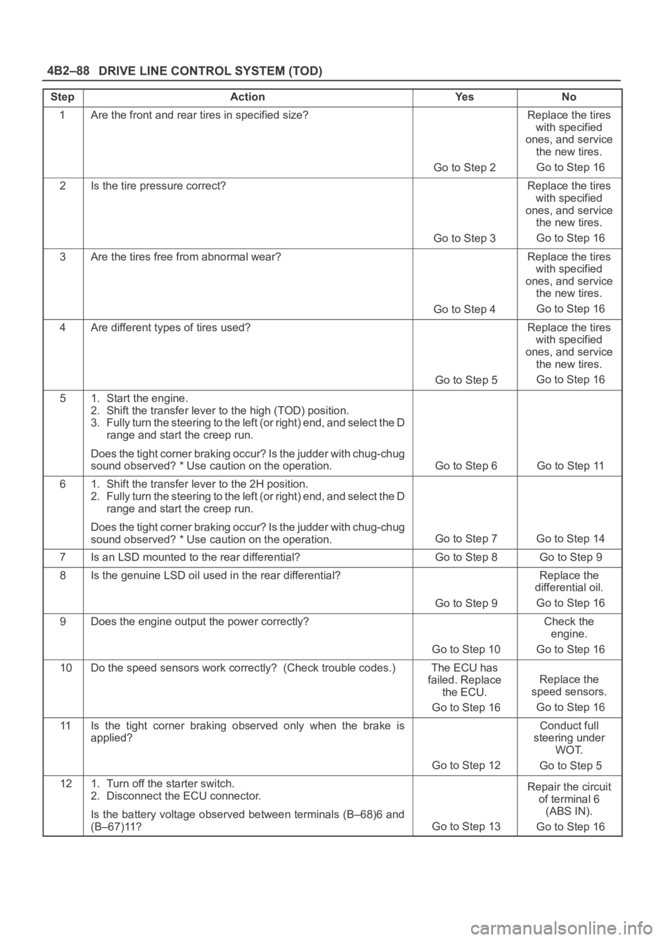
DRIVE LINE CONTROL SYSTEM (TOD) 4B2–88
StepActionYe sNo
1Are the front and rear tires in specified size?
Go to Step 2
Replace the tires
with specified
ones, and service
the new tires.
Go to Step 16
2Is the tire pressure correct?
Go to Step 3
Replace the tires
with specified
ones, and service
the new tires.
Go to Step 16
3Are the tires free from abnormal wear?
Go to Step 4
Replace the tires
with specified
ones, and service
the new tires.
Go to Step 16
4Are different types of tires used?
Go to Step 5
Replace the tires
with specified
ones, and service
the new tires.
Go to Step 16
51. Start the engine.
2. Shift the transfer lever to the high (TOD) position.
3. Fully turn the steering to the left (or right) end, and select the D
range and start the creep run.
Does the tight corner braking occur? Is the judder with chug-chug
sound observed? * Use caution on the operation.
Go to Step 6 Go to Step 11
61. Shift the transfer lever to the 2H position.
2. Fully turn the steering to the left (or right) end, and select the D
range and start the creep run.
Does the tight corner braking occur? Is the judder with chug-chug
sound observed? * Use caution on the operation.
Go to Step 7 Go to Step 14
7Is an LSD mounted to the rear differential? Go to Step 8 Go to Step 9
8Is the genuine LSD oil used in the rear differential?
Go to Step 9
Replace the
differential oil.
Go to Step 16
9Does the engine output the power correctly?
Go to Step 10
Check the
engine.
Go to Step 16
10Do the speed sensors work correctly? (Check trouble codes.)The ECU has
failed. Replace
the ECU.
Go to Step 16
Replace the
speed sensors.
Go to Step 16
11Is the tight corner braking observed only when the brake is
applied?
Go to Step 12
Conduct full
steering under
WOT.
Go to Step 5
121. Turn off the starter switch.
2. Disconnect the ECU connector.
Is the battery voltage observed between terminals (B–68)6 and
(B–67)11?
Go to Step 13
Repair the circuit
of terminal 6
(ABS IN).
Go to Step 16
Page 729 of 6000
4D1–8
TRANSFER CASE (STANDARD TYPE)
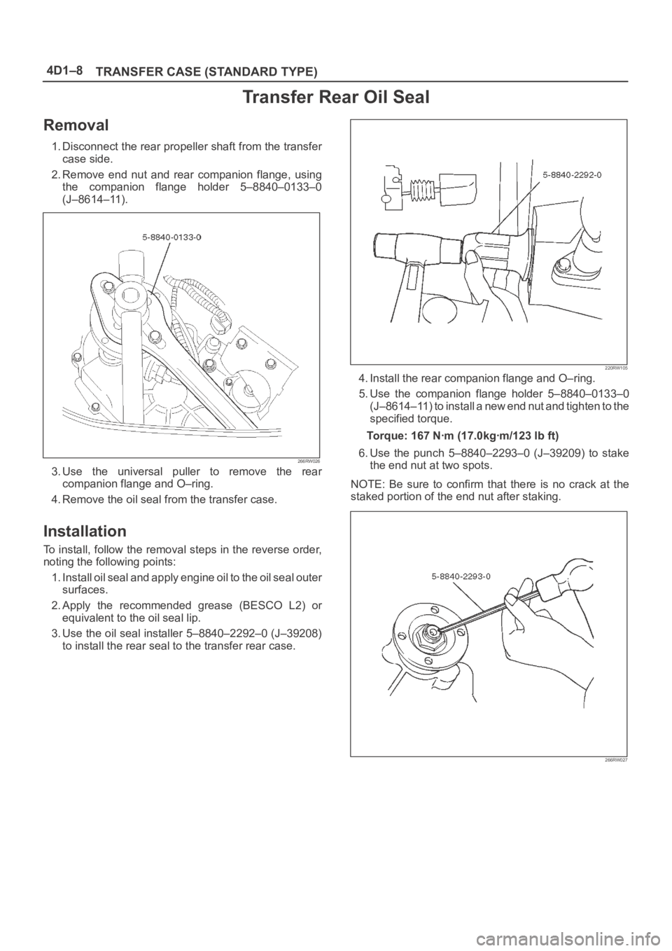
Transfer Rear Oil Seal
Removal
1. Disconnect the rear propeller shaft from the transfer
case side.
2. Remove end nut and rear companion flange, using
the companion flange holder 5–8840–0133–0
(J–8614–11).
266RW026
3. Use the universal puller to remove the rear
companion flange and O–ring.
4. Remove the oil seal from the transfer case.
Installation
To install, follow the removal steps in the reverse order,
noting the following points:
1. Install oil seal and apply engine oil to the oil seal outer
surfaces.
2. Apply the recommended grease (BESCO L2) or
equivalent to the oil seal lip.
3. Use the oil seal installer 5–8840–2292–0 (J–39208)
to install the rear seal to the transfer rear case.
220RW105
4. Install the rear companion flange and O–ring.
5. Use the companion flange holder 5–8840–0133–0
(J–8614–11) to install a new end nut and tighten to the
specified torque.
Torque: 167 Nꞏm (17.0kgꞏm/123 lb ft)
6. Use the punch 5–8840–2293–0 (J–39209) to stake
the end nut at two spots.
NOTE: Be sure to confirm that there is no crack at the
staked portion of the end nut after staking.
266RW027
Page 738 of 6000
TRANSFER CASE (STANDARD TYPE)
4D1–17
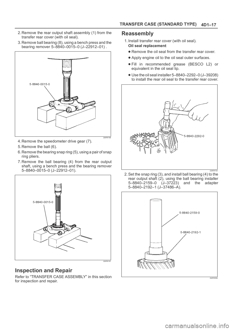
2. Remove the rear output shaft assembly (1) from the
transfer rear cover (with oil seal).
3. Remove ball bearing (8), using a bench press and the
bearing remover 5–8840–0015–0 (J–22912–01) .
226RW186
4. Remove the speedometer drive gear (7).
5. Remove the ball (6).
6. Remove the bearing snap ring (5), using a pair of snap
ring pliers.
7. Remove the ball bearing (4) from the rear output
shaft, using a bench press and the bearing remover
5–8840–0015–0 (J–22912–01).
226RW187
Inspection and Repair
Refer to “TRANSFER CASE ASSEMBLY” in this section
for inspection and repair.
Reassembly
1. Install transfer rear cover (with oil seal).
Oil seal replacement
Remove the oil seal from the transfer rear cover.
Apply engine oil to the oil seal outer surfaces.
Fill in recommended grease (BESCO L2) or
equivalent in the oil seal lip.
Use the oil seal installer 5–8840–2292–0 (J–39208)
to install the rear oil seal to the transfer rear cover.
220RW104
2. Set the snap ring (3), and install ball bearing (4) to the
rear output shaft (2), using the ball bearing installer
5–8840–2159–0 (J–37223) and the adapter
5–8840–2192–1 (J–37486–A).
262RW068
Page 745 of 6000
4D1–24
TRANSFER CASE (STANDARD TYPE)
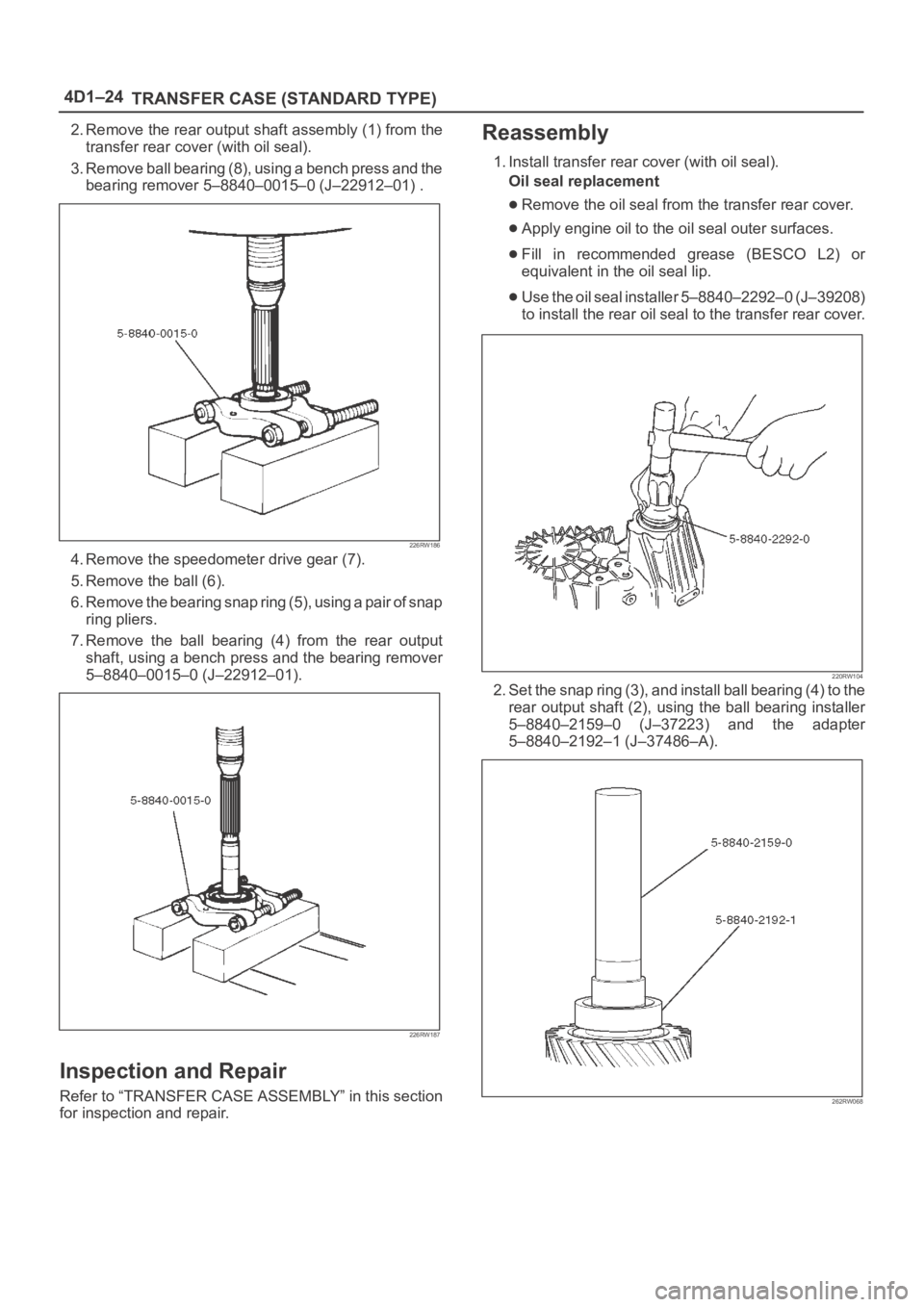
2. Remove the rear output shaft assembly (1) from the
transfer rear cover (with oil seal).
3. Remove ball bearing (8), using a bench press and the
bearing remover 5–8840–0015–0 (J–22912–01) .
226RW186
4. Remove the speedometer drive gear (7).
5. Remove the ball (6).
6. Remove the bearing snap ring (5), using a pair of snap
ring pliers.
7. Remove the ball bearing (4) from the rear output
shaft, using a bench press and the bearing remover
5–8840–0015–0 (J–22912–01).
226RW187
Inspection and Repair
Refer to “TRANSFER CASE ASSEMBLY” in this section
for inspection and repair.
Reassembly
1. Install transfer rear cover (with oil seal).
Oil seal replacement
Remove the oil seal from the transfer rear cover.
Apply engine oil to the oil seal outer surfaces.
Fill in recommended grease (BESCO L2) or
equivalent in the oil seal lip.
Use the oil seal installer 5–8840–2292–0 (J–39208)
to install the rear oil seal to the transfer rear cover.
220RW104
2. Set the snap ring (3), and install ball bearing (4) to the
rear output shaft (2), using the ball bearing installer
5–8840–2159–0 (J–37223) and the adapter
5–8840–2192–1 (J–37486–A).
262RW068
Page 758 of 6000
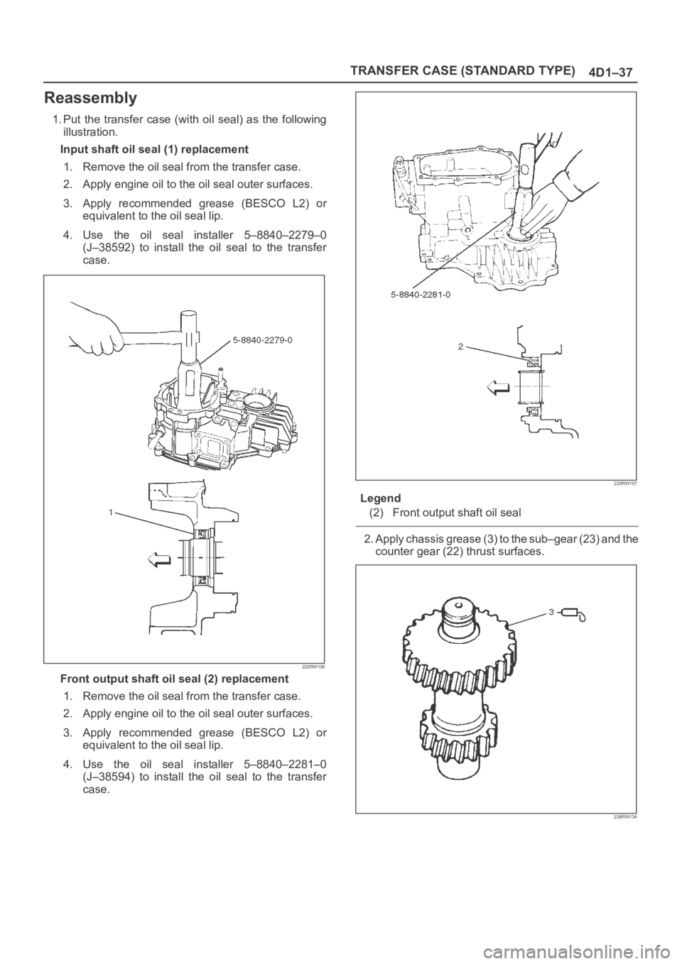
TRANSFER CASE (STANDARD TYPE)
4D1–37
Reassembly
1. Put the transfer case (with oil seal) as the following
illustration.
Input shaft oil seal (1) replacement
1. Remove the oil seal from the transfer case.
2. Apply engine oil to the oil seal outer surfaces.
3. Apply recommended grease (BESCO L2) or
equivalent to the oil seal lip.
4. Use the oil seal installer 5–8840–2279–0
(J–38592) to install the oil seal to the transfer
case.
220RW106
Front output shaft oil seal (2) replacement
1. Remove the oil seal from the transfer case.
2. Apply engine oil to the oil seal outer surfaces.
3. Apply recommended grease (BESCO L2) or
equivalent to the oil seal lip.
4. Use the oil seal installer 5–8840–2281–0
(J–38594) to install the oil seal to the transfer
case.
220RW107
Legend
(2) Front output shaft oil seal
2. Apply chassis grease (3) to the sub–gear (23) and the
counter gear (22) thrust surfaces.
226RW134