engine oil capacity OPEL FRONTERA 1998 Workshop Manual
[x] Cancel search | Manufacturer: OPEL, Model Year: 1998, Model line: FRONTERA, Model: OPEL FRONTERA 1998Pages: 6000, PDF Size: 97 MB
Page 281 of 6000

1. Perform oil return operation.
2. Discharge and recover the refrigerant and remove
the compressor.
3. Drain the compressor oil and measure the extracted
oil.
4. Check the compressor oil for contamination.
5. Adjust the oil level as required.
6. Evacuate, charge and perform the oil return
operation.
7. Check the system operation.
Contamination of Compressor Oil
Unlike engine oil, no cleaning agent is added to the
compressor oil. Even if the compressor runs for a long
period of time (approximately one season), the oil never
becomes contaminated as long as there is nothing
wrong with the compressor or its method of use.
Inspect the extracted oil for any of the following
conditions:
The capacity of the oil has increased.
The oil has changed to red.
Foreign substances, metal powder, etc., are present
in the oil.
If any of these conditions exists, the compressor
oil is contaminated. Whenever contaminated
compressor oil is discovered, the receiver/drier
must be replaced.
Oil Return Operation
There is close affinity between the oil and the
refrigerant. During normal operation, part of the oil
recirculates with the refrigerant in the system. When
checking the amount of oil in the system, or replacing
any component of the system, the compressor must be
run in advance for oil return operation. The procedure
is as follows:
1. Open all the doors and the engine hood.
2. Start the engine and air conditioning switch to "ON"
and set the fan control knob at its highest position.
3. Run the compressor for more than 20 minutes
between 800 and 1,000 rpm in order to operate the
system.
4. Stop the engine.
Replacement of Component Parts
When replacing the system component parts, supply
the following amount of oil to the component parts to be
installed.
Compressor Leak Testing (External and
Internal)
Bench-Check Procedure
1. Install test plate J-39893 on rear head of compressor.
2. Using Refrigerant Recovery System, attach center
hose of manifold gage set on charging station to a
refrigerant drum standing in an upright drum.
3. Connect charging station high and low pressure
lines to corresponding fittings on test plate J-39893.
Suction port (low-side) of compressor has large
internal opening. Discharge port (high-side) has
smaller internal opening into compressor and
deeper recess.
4. Open low pressure control, high pressure control
and refrigerant control on charging station to allow
refrigerant vapor to flow into compressor.
5. Using a leak detector, check for leaks at pressure
relief valve, rear head switch location, compressor
front and rear head seals, center cylinder seal,
through bolt head gaskets and compressor shaft
seal. After checking, shut off low pressure control
and high-pressure control on charging station.
6. If an external leak is present, perform the necessary
corrective measures and recheck for leaks to make
certain the leak has been connected.
7. Recover the refrigerant.
8. Disconnect both hoses from the test plate J-39893.
9. Add 90 ml (3 oz.) new PAG lubricant to the
compressor assembly. Rotate the complete
compressor assembly (not the crankshaft or drive
plate hub) slowly several turns to distribute oil to all
cylinder and piston areas.
10. Install a M9
1.25 threaded nut on the compressor
crankshaft if the drive plate and clutch assembly are
not installed.
11. Using a box-end wrench or socket and handle,
rotate the compressor crankshaft or clutch drive
plate on the crankshaft several turns to insure
piston assembly to cylinder wall lubrication.
12. Using Refrigerant Recovery System, connect the
charging station high-pressure line to the test plate
J-39893 high-side connector.
13. Using Refrigerant Recovery System, connect the
charging station low-pressure line to the low
pressure port of the test plate J-39893. Oil will drain
out of the compressor suction port if the compressor
is positioned with the suction port downward. (Component parts to be (Amount of Oil)
installed)
Evaporator 50 cc (1.7 fl. oz.)
Condenser 30 cc (1.0 fl. oz.)
Receiver/dryer 30 cc (1.0 fl. oz.)
Refrigerant line (one 10 cc (0.3 fl. oz.)
piece)
(Amount of oil drained (Charging amount of oil
from used compressor) to new compressor)
more than 90 cc same as drained amount
(3.0 fl.oz)
less than 90 cc (3.0 fl.oz) 90 cc (3.0 fl.oz)
Page 764 of 6000
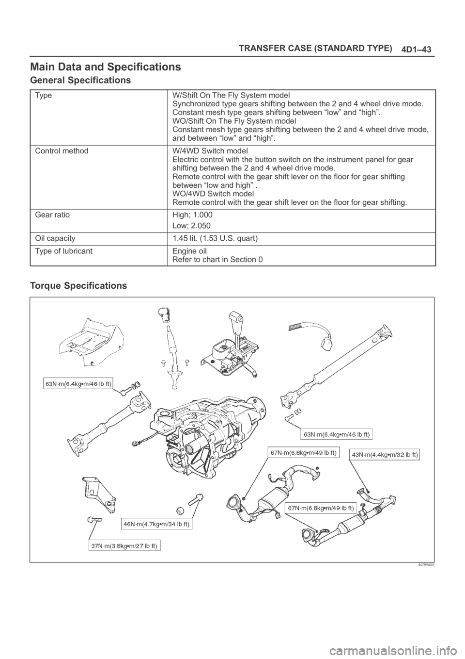
TRANSFER CASE (STANDARD TYPE)
4D1–43
Main Data and Specifications
General Specifications
Ty p eW/Shift On The Fly System model
Synchronized type gears shifting between the 2 and 4 wheel drive mode.
Constant mesh type gears shifting between “low” and “high”.
WO/Shift On The Fly System model
Constant mesh type gears shifting between the 2 and 4 wheel drive mode,
and between “low” and “high”.
Control methodW/4WD Switch model
Electric control with the button switch on the instrument panel for gear
shifting between the 2 and 4 wheel drive mode.
Remote control with the gear shift lever on the floor for gear shifting
between “low and high” .
WO/4WD Switch model
Remote control with the gear shift lever on the floor for gear shifting.
Gear ratioHigh; 1.000
Low; 2.050
Oil capacity1.45 lit. (1.53 U.S. quart)
Type of lubricantEngine oil
Refer to chart in Section 0
Torque Specifications
E07RW037
Page 1046 of 6000
6A–90
ENGINE MECHANICAL
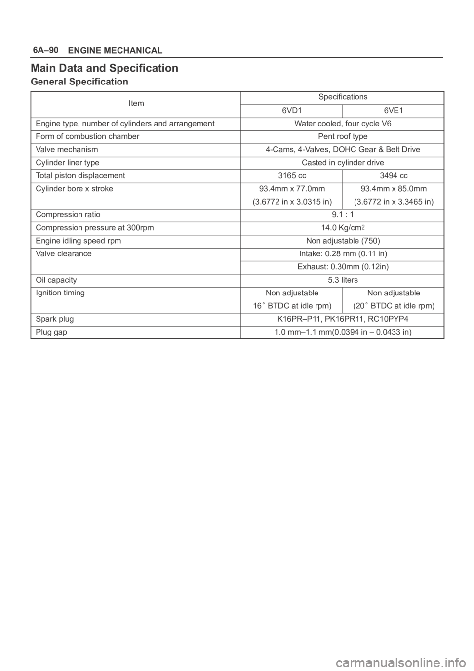
Main Data and Specification
General Specification
ItemSpecificationsItem6VD16VE1
Engine type, number of cylinders and arrangementWater cooled, four cycle V6
Form of combustion chamberPent roof type
Valve mechanism4-Cams, 4-Valves, DOHC Gear & Belt Drive
Cylinder liner typeCasted in cylinder drive
Total piston displacement3165 cc3494 cc
Cylinder bore x stroke93.4mm x 77.0mm93.4mm x 85.0mm
(3.6772 in x 3.0315 in)(3.6772 in x 3.3465 in)
Compression ratio9.1 : 1
Compression pressure at 300rpm14.0 Kg/cm
Engine idling speed rpmNon adjustable (750)
Valve clearanceIntake: 0.28 mm (0.11 in)
Exhaust: 0.30mm (0.12in)
Oil capacity5.3 liters
Ignition timingNon adjustableNon adjustable
16 BTDC at idle rpm)(20 BTDC at idle rpm)
Spark plugK16PR–P11, PK16PR11, RC10PYP4
Plug gap1.0 mm–1.1 mm(0.0394 in – 0.0433 in)
Page 1493 of 6000
6G–14
ENGINE LUBRICATION
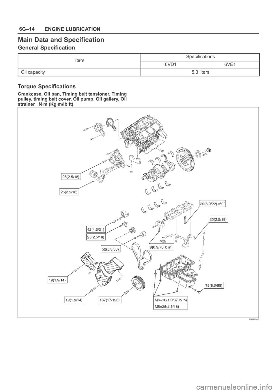
Main Data and Specification
General Specification
ItemSpecificationsItem6VD16VE1
Oil capacity5.3 liters
Torque Specifications
Crankcase, Oil pan, Timing belt tensioner, Timing
pulley, timing belt cover, Oil pump, Oil gallery, Oil
strainer Nꞏm (Kgꞏm/lb ft)
E06RW045
Page 1736 of 6000

ENGINE MECHANICAL 6A – 3
SERVICE INFORMATION
MAIN DATA AND SPECIFICATION
Engine type Diesel, four cycle water cooled inline
Camshaft type DOHC
Number of cylinders 4
Bore x stroke (mm) 95.4 x 104.9
Total piston displacement (cc) 2999
Compression ratio (to 1) 19.0
For Europe : 18.5
Engine weight (dry) N (kg/lb) 2492 (254/560) (A/T)
For Europe : 2422 (247/545) (A/T)
2649 (270/593) (M/T)
For Europe : 2697 (275/606) (M/T)
Engine idling speed (Reference) RPM 720
Compression pressure kpa (kg/cm
2/psi)-rpm 3040 (31/441)-200
Firing order 1–3–4–2
VALVE SYSTEM
Intake valves open at: B.T.D.C. 3°
close at: A.B.D.C. 57.6°
Exhaust valves open at: B.B.D.C. 56.5°
close at: A.T.D.C. 5°
Valve clearance (at cold) mm (in)
intake: 0.15 (0.006)
exhaust: 0.25 (0.01)
Oil filter Full flow and bypass combined type
Oil capacity (Original factory fill or rebuilt engine) 9.0 liters (7.9 US quarts)
Oil capacity (Service change)
with filter change 6.0 liters (6.3 US quarts)
without filter change 5.0 liters (5.3 US quarts)
Oil cooler Water cooled type
Inter cooler Air cooled type
Turbocharger method
Control method Wastegate control
Lubrication Pressurized control
Cooling method Coolant cooled
Crankshaft
As tufftriding (Nitrizing treatment) is applied to increase
crankshaft strength, crankpins and journals should not
be reground.
Piston Cooling
An oiling jet device for piston cooling is provided in the
lubricating oil circuit from the cylinder block oil gallery
via a check valve.
Take care not to damage any oiling jet when removing
and installing piston and connecting assembly.
Fuel Injection System
The injection system is oil rail type.
Quick On Start 4 System
QOS4 preheating system which features a quick-on
glow plug with thermometer control of the glowing time
and the afterglow time function, is applied.
Page 1846 of 6000

ENGINE FUEL 6C – 1
ENGINE FUEL
CONTENTS
GENERAL DESCRIPTION
General Description . . . . . . . . . . . . . . . . . . 6C–1
On-Vehicle Service . . . . . . . . . . . . . . . . . . 6C–7
Fuel Filter Assembly . . . . . . . . . . . . . . . . 6C–7
Fuel Filter Cartridge . . . . . . . . . . . . . . . . 6C–7
Injector . . . . . . . . . . . . . . . . . . . . . . . . . . 6C–9
Fuel Pump Pipe . . . . . . . . . . . . . . . . . . . 6C–13High Pressure Oil Pump . . . . . . . . . . . . . 6C–15
Fuel Tank . . . . . . . . . . . . . . . . . . . . . . . . 6C–20
Fuel Gauge Unit . . . . . . . . . . . . . . . . . . . 6C–21
Fuel Filler Cap . . . . . . . . . . . . . . . . . . . . 6C–21
To realize the compatibility between low exhaust
emission and high engine output, an HEUI
(Hydraulically actuated Electronically controlled Unit
Injector) system, has been introduced. This system is
comprised of a hydraulic system, fuel system, and
electronic control system, using a high-pressure oil
pump in place of the conventional fuel injection pump.
The oil pressurized by means of this pump and by
signals from the ECM (Electronic Control Module)
actuates the fuel injector provided for each cylinder.
Inside of the fuel injector, fuel pressure is increased due
to the high-pressure oil. The ECM detects the driving
state of the vehicle, forms, signals sent by engine and
other part sensors, which determines the optimum fuel
injection amount and timing, thus controlling the fuel
injectors. Thus high engine output, good fuel economy,
and low exhaust emission are realized.When working on the fuel system, there are several
things to keep in mind:
1) Any time the fuel system is being worked on,
disconnect the negative battery cable except for
those tests where battery voltage is required.
2) Always keep a dry chemical (Class B) fire
extinguisher near the work area.
3) Replace all pipes with the same pipe and fittings
that were removed.
Clean and inspect “O” rings. Replace where
required.
4) Always relieve the line pressure before servicing
any fuel system components.
5) Do not attempt repairs on the fuel system until you
have read the instructions and checked the pictures
relating to that repair.
6) After maintenance work, push priming pump and
send enough fuel to the fuel system before starting
the engine.
NOTE: In comparison with the conventional engine,
the capacity of fuel passage in the 4JX1 engine is
larger. It takes the priming pump more time to fill the
engine with fuel.
Page 1853 of 6000

6C – 8 ENGINE FUEL
REASSEMBLY
1. Clean the cartridge mounting surface of the filter
body so that the cartridge can be secured.
Apply engine oil thinly to new cartridge O-ring.
2. To facilitate bleeding, fill the new cartridge with light
oil.
3. Tighten the cartridge until O-ring comes in contact
with the seal, taking care not to spill the light oil.
4. Retighten 1/3 – 2/3 using a filter wrench.
Filter wrench: 5-8840-0203-0
Bleeding
1. Loosen air bleeding plug.
2. Operate priming pump to bleed the air in the fuel
line.
3. Operate the priming pump until the fuel is overflow
from air bleeding plug.
4. Tighten the air bleeding plug.
5. Start the engine, and if it is not started in 10
seconds or less, repeat the bleeding steps.
6. Make sure of no fuel leakage, and tighten the
priming pump.
Legend
(1) Priming Pump
NOTE: In comparison with the conventional engine,
the capacity of fuel passage in the 4JX1 engine is
larger. It takes the priming pump more time to fill the
engine with fuel.
012RW078
1
012RW111
Page 2134 of 6000
ENGINE LUBRICATION 6G – 3
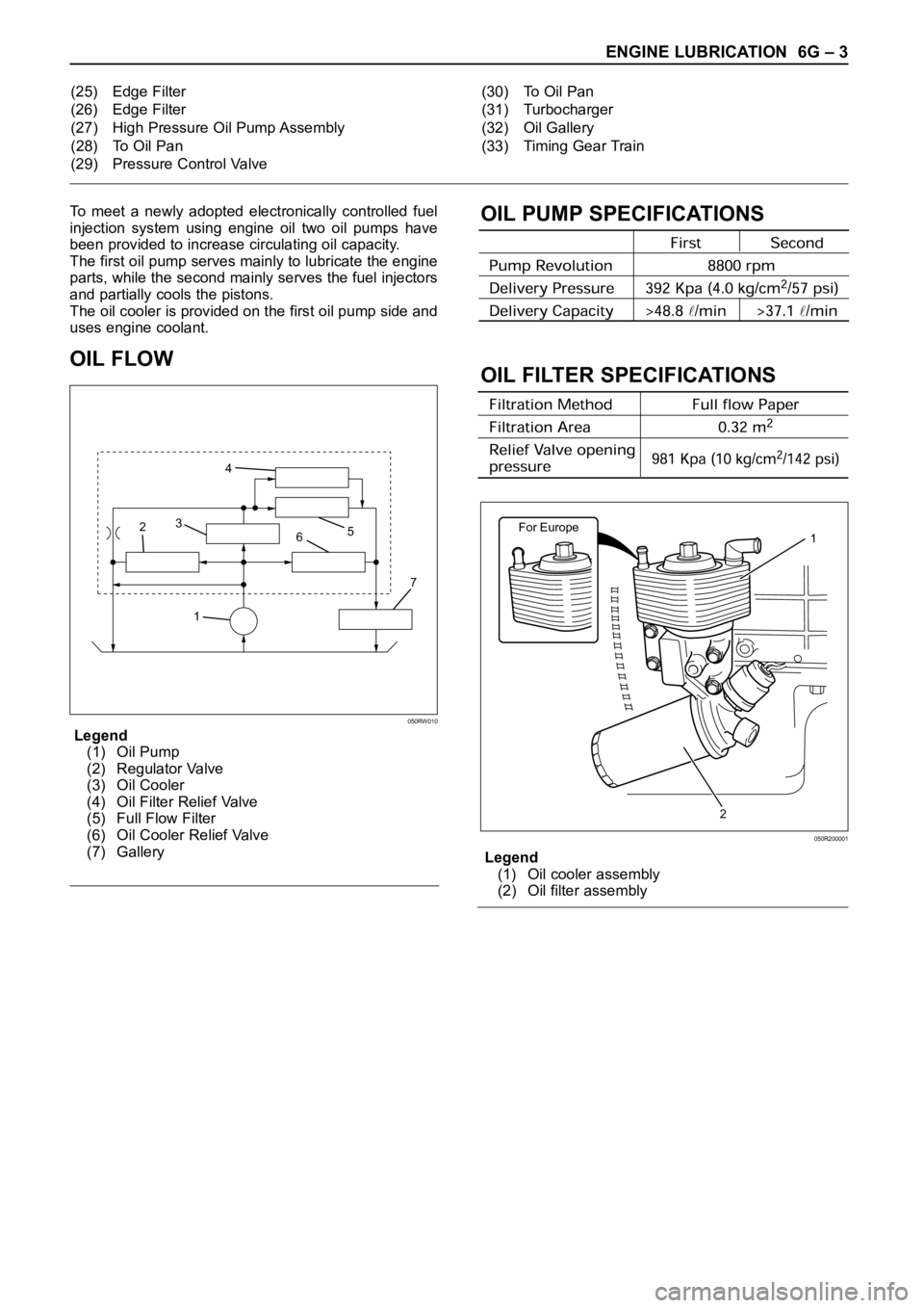
To meet a newly adopted electronically controlled fuel
injection system using engine oil two oil pumps have
been provided to increase circulating oil capacity.
The first oil pump serves mainly to lubricate the engine
parts, while the second mainly serves the fuel injectors
and partially cools the pistons.
The oil cooler is provided on the first oil pump side and
uses engine coolant.
OIL FLOW
Legend
(1) Oil Pump
(2) Regulator Valve
(3) Oil Cooler
(4) Oil Filter Relief Valve
(5) Full Flow Filter
(6) Oil Cooler Relief Valve
(7) Gallery
OIL PUMP SPECIFICATIONS
OIL FILTER SPECIFICATIONS
Legend
(1) Oil cooler assembly
(2) Oil filter assembly (25) Edge Filter
(26) Edge Filter
(27) High Pressure Oil Pump Assembly
(28) To Oil Pan
(29) Pressure Control Valve(30) To Oil Pan
(31) Turbocharger
(32) Oil Gallery
(33) Timing Gear Train
17 65 4
3
2
050RW010
For Europe1
2
050R200001
Page 2386 of 6000
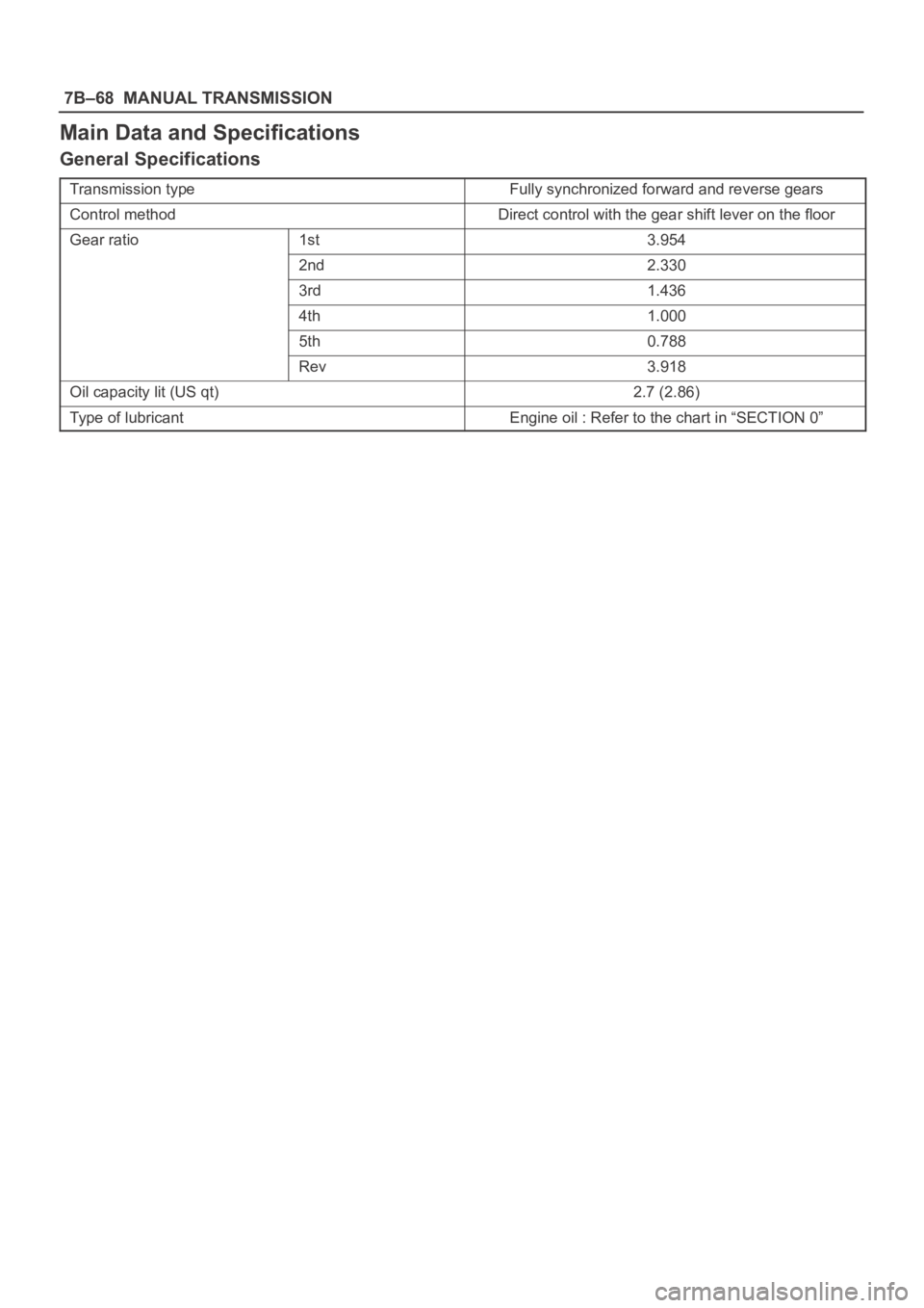
7B–68MANUAL TRANSMISSION
Main Data and Specifications
General Specifications
Transmission typeFully synchronized forward and reverse gears
Control methodDirect control with the gear shift lever on the floor
Gear ratio1st3.954
2nd2.330
3rd1.436
4th1.000
5th0.788
Rev3.918
Oil capacity lit (US qt)2.7 (2.86)
Type of lubricantEngine oil : Refer to the chart in “SECTION 0”
Page 3784 of 6000

1. Perform oil return operation.
2. Discharge and recover the refrigerant and remove
the compressor.
3. Drain the compressor oil and measure the extracted
oil.
4. Check the compressor oil for contamination.
5. Adjust the oil level as required.
6. Evacuate, charge and perform the oil return
operation.
7. Check the system operation.
Contamination of Compressor Oil
Unlike engine oil, no cleaning agent is added to the
compressor oil. Even if the compressor runs for a long
period of time (approximately one season), the oil never
becomes contaminated as long as there is nothing
wrong with the compressor or its method of use.
Inspect the extracted oil for any of the following
conditions:
The capacity of the oil has increased.
The oil has changed to red.
Foreign substances, metal powder, etc., are present
in the oil.
If any of these conditions exists, the compressor
oil is contaminated. Whenever contaminated
compressor oil is discovered, the receiver/drier
must be replaced.
Oil Return Operation
There is close affinity between the oil and the
refrigerant. During normal operation, part of the oil
recirculates with the refrigerant in the system. When
checking the amount of oil in the system, or replacing
any component of the system, the compressor must be
run in advance for oil return operation. The procedure
is as follows:
1. Open all the doors and the engine hood.
2. Start the engine and air conditioning switch to "ON"
and set the fan control knob at its highest position.
3. Run the compressor for more than 20 minutes
between 800 and 1,000 rpm in order to operate the
system.
4. Stop the engine.
Replacement of Component Parts
When replacing the system component parts, supply
the following amount of oil to the component parts to be
installed.
Compressor Leak Testing (External and
Internal)
Bench-Check Procedure
1. Install test plate J-39893 on rear head of compressor.
2. Using Refrigerant Recovery System, attach center
hose of manifold gage set on charging station to a
refrigerant drum standing in an upright drum.
3. Connect charging station high and low pressure
lines to corresponding fittings on test plate J-39893.
Suction port (low-side) of compressor has large
internal opening. Discharge port (high-side) has
smaller internal opening into compressor and
deeper recess.
4. Open low pressure control, high pressure control
and refrigerant control on charging station to allow
refrigerant vapor to flow into compressor.
5. Using a leak detector, check for leaks at pressure
relief valve, rear head switch location, compressor
front and rear head seals, center cylinder seal,
through bolt head gaskets and compressor shaft
seal. After checking, shut off low pressure control
and high-pressure control on charging station.
6. If an external leak is present, perform the necessary
corrective measures and recheck for leaks to make
certain the leak has been connected.
7. Recover the refrigerant.
8. Disconnect both hoses from the test plate J-39893.
9. Add 90 ml (3 oz.) new PAG lubricant to the
compressor assembly. Rotate the complete
compressor assembly (not the crankshaft or drive
plate hub) slowly several turns to distribute oil to all
cylinder and piston areas.
10. Install a M9
1.25 threaded nut on the compressor
crankshaft if the drive plate and clutch assembly are
not installed.
11. Using a box-end wrench or socket and handle,
rotate the compressor crankshaft or clutch drive
plate on the crankshaft several turns to insure
piston assembly to cylinder wall lubrication.
12. Using Refrigerant Recovery System, connect the
charging station high-pressure line to the test plate
J-39893 high-side connector.
13. Using Refrigerant Recovery System, connect the
charging station low-pressure line to the low
pressure port of the test plate J-39893. Oil will drain
out of the compressor suction port if the compressor
is positioned with the suction port downward. (Component parts to be (Amount of Oil)
installed)
Evaporator 50 cc (1.7 fl. oz.)
Condenser 30 cc (1.0 fl. oz.)
Receiver/dryer 30 cc (1.0 fl. oz.)
Refrigerant line (one 10 cc (0.3 fl. oz.)
piece)
(Amount of oil drained (Charging amount of oil
from used compressor) to new compressor)
more than 90 cc same as drained amount
(3.0 fl.oz)
less than 90 cc (3.0 fl.oz) 90 cc (3.0 fl.oz)