height adjustment OPEL FRONTERA 1998 Workshop Manual
[x] Cancel search | Manufacturer: OPEL, Model Year: 1998, Model line: FRONTERA, Model: OPEL FRONTERA 1998Pages: 6000, PDF Size: 97 MB
Page 983 of 6000

6A–27
ENGINE MECHANICAL
Exhaust Manifold RH
Removal
1. Disconnect battery ground cable.
2. Remove torsion bar. Refer to removal procedure in
Front Suspension section.
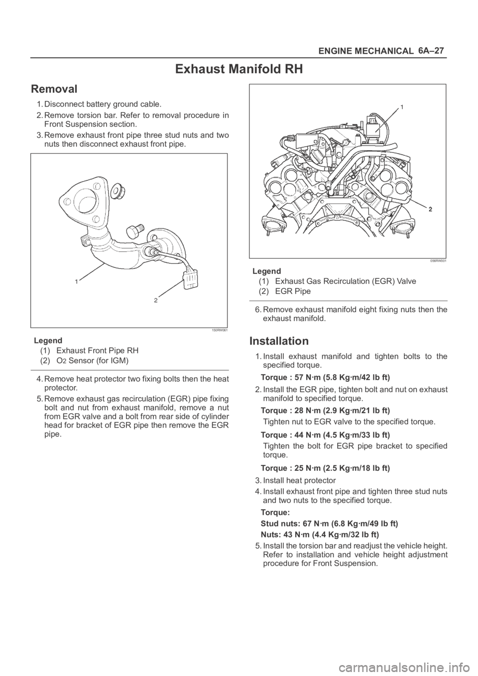
3. Remove exhaust front pipe three stud nuts and two
nuts then disconnect exhaust front pipe.
150RW061
Legend
(1) Exhaust Front Pipe RH
(2) O
2 Sensor (for IGM)
4. Remove heat protector two fixing bolts then the heat
protector.
5. Remove exhaust gas recirculation (EGR) pipe fixing
bolt and nut from exhaust manifold, remove a nut
from EGR valve and a bolt from rear side of cylinder
head for bracket of EGR pipe then remove the EGR
pipe.
056RW001
Legend
(1) Exhaust Gas Recirculation (EGR) Valve
(2) EGR Pipe
6. Remove exhaust manifold eight fixing nuts then the
exhaust manifold.
Installation
1. Install exhaust manifold and tighten bolts to the
specified torque.
Torque : 57 Nꞏm (5.8 Kgꞏm/42 lb ft)
2. Install the EGR pipe, tighten bolt and nut on exhaust
manifold to specified torque.
Torque : 28 Nꞏm (2.9 Kgꞏm/21 lb ft)
Tighten nut to EGR valve to the specified torque.
Torque : 44 Nꞏm (4.5 Kgꞏm/33 lb ft)
Tighten the bolt for EGR pipe bracket to specified
torque.
Torque : 25 Nꞏm (2.5 Kgꞏm/18 lb ft)
3. Install heat protector
4. Install exhaust front pipe and tighten three stud nuts
and two nuts to the specified torque.
To r q u e :
Stud nuts: 67 Nꞏm (6.8 Kgꞏm/49 lb ft)
Nuts: 43 Nꞏm (4.4 Kgꞏm/32 lb ft)
5. Install the torsion bar and readjust the vehicle height.
Refer to installation and vehicle height adjustment
procedure for Front Suspension.
Page 1782 of 6000

ENGINE MECHANICAL 6A – 49
INSPECTION AND REPAIR
Make the necessary adjustments, repairs, and part
replacements if excessive wear or damage is
discovered during inspection.
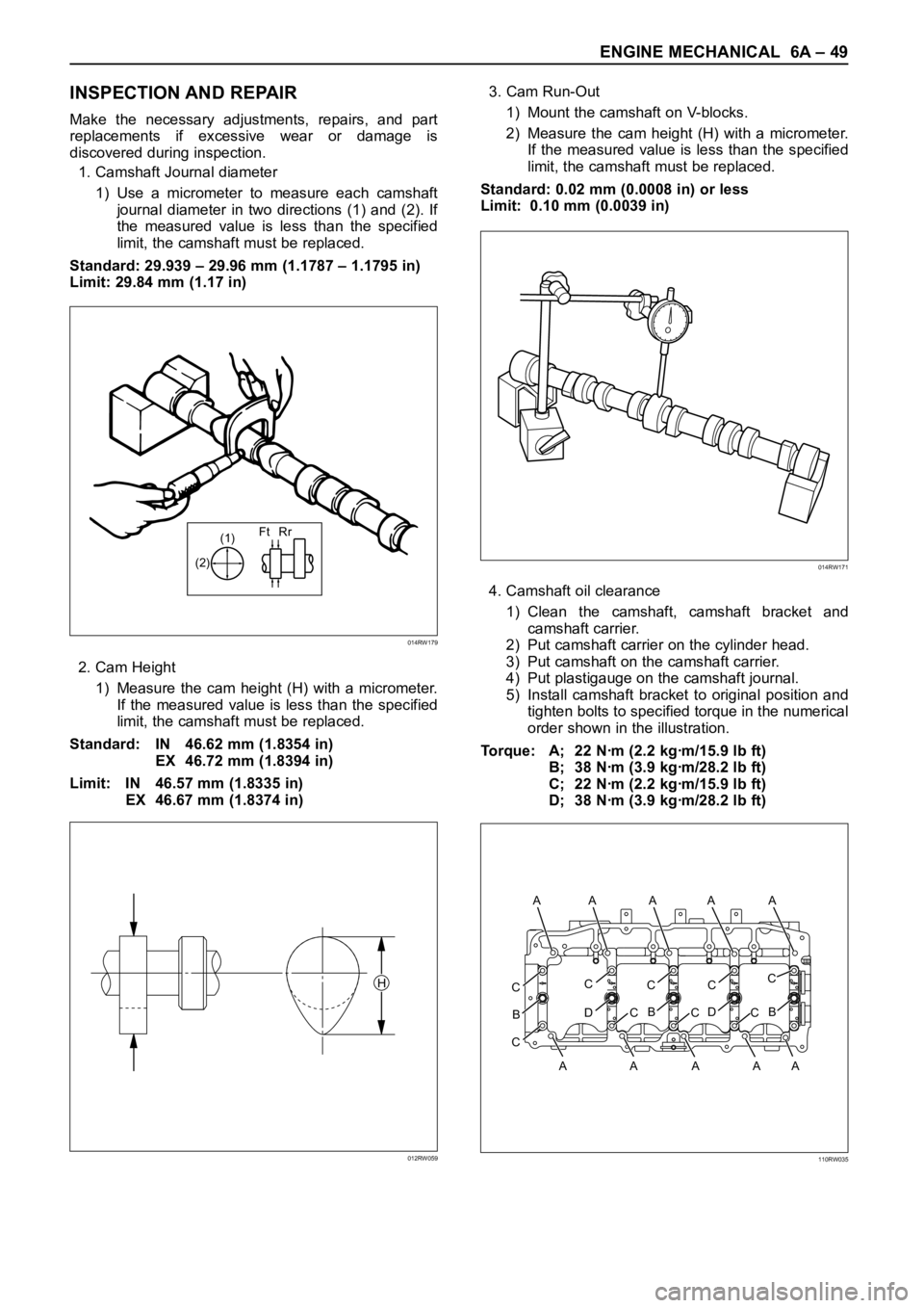
1. Camshaft Journal diameter
1) Use a micrometer to measure each camshaft
journal diameter in two directions (1) and (2). If
the measured value is less than the specified
limit, the camshaft must be replaced.
Standard: 29.939 – 29.96 mm (1.1787 – 1.1795 in)
Limit: 29.84 mm (1.17 in)
2. Cam Height
1) Measure the cam height (H) with a micrometer.
If the measured value is less than the specified
limit, the camshaft must be replaced.
Standard: IN 46.62 mm (1.8354 in)
EX 46.72 mm (1.8394 in)
Limit: IN 46.57 mm (1.8335 in)
EX 46.67 mm (1.8374 in)3. Cam Run-Out
1) Mount the camshaft on V-blocks.
2) Measure the cam height (H) with a micrometer.
If the measured value is less than the specified
limit, the camshaft must be replaced.
Standard: 0.02 mm (0.0008 in) or less
Limit: 0.10 mm (0.0039 in)
4. Camshaft oil clearance
1) Clean the camshaft, camshaft bracket and
camshaft carrier.
2) Put camshaft carrier on the cylinder head.
3) Put camshaft on the camshaft carrier.
4) Put plastigauge on the camshaft journal.
5) Install camshaft bracket to original position and
tighten bolts to specified torque in the numerical
order shown in the illustration.
Torque: A; 22 Nꞏm (2.2 kgꞏm/15.9 lb ft)
B; 38 Nꞏm (3.9 kgꞏm/28.2 lb ft)
C; 22 Nꞏm (2.2 kgꞏm/15.9 lb ft)
D; 38 Nꞏm (3.9 kgꞏm/28.2 lb ft)
(1)Ft Rr
(2)
014RW179
H
012RW059
014RW171
CC
D
B
CC
B
CC
D
CC
B
C
A AA A A A
AAAA
110RW035
Page 1794 of 6000

ENGINE MECHANICAL 6A – 61
24. Remove fuel pipe between fuel pump and intake
manifold.
25. Remove fuel return pipe from rear of cylinder head.
26. Remove intake manifold assembly.
27. Disconnect glow plug harness and remove glow
plug.
28. Remove cylinder head cover.
29. Remove injector harness connector.
30. Disconnect harness connector from oil pressure
sensor and oil temperature sensor on the oil rail.
31. Remove injector harness assembly.
32. Remove injector clamp.
33. Remove injector is fixed bolts.
34. Remove injector assembly.
35. Remove oil rail.
36. Remove camshaft carrier assembly with camshaft.
37. Remove cylinder head assembly.
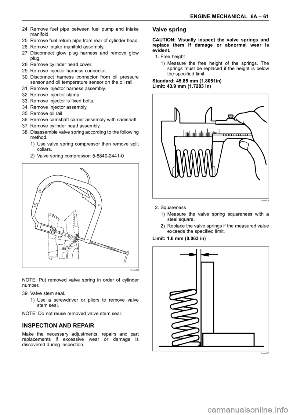
38. Disassemble valve spring according to the following
method.
1) Use valve spring compressor then remove split
collars.
2) Valve spring compressor: 5-8840-2441-0
NOTE: Put removed valve spring in order of cylinder
number.
39. Valve stem seal.
1) Use a screwdriver or pliers to remove valve
stem seal.
NOTE: Do not reuse removed valve stem seal.
INSPECTION AND REPAIR
Make the necessary adjustments, repairs and part
replacements if excessive wear or damage is
discovered during inspection.
Va l v e s p r i n g
CAUTION: Visually inspect the valve springs and
replace them if damage or abnormal wear is
evident.
1. Free height
1) Measure the free height of the springs. The
springs must be replaced if the height is below
the specified limit.
Standard: 45.85 mm (1.8051in)
Limit: 43.9 mm (1.7283 in)
2. Squareness
1) Measure the valve spring squareness with a
steel square.
2) Replace the valve springs if the measured value
exceeds the specified limit.
Limit: 1.6 mm (0.063 in)
014rw042
014rs004
014rs005
Page 2528 of 6000

CLUTCH7C–19
Installation
1. Install damper cylinder assembly (except V6 LHD).
2. Install master cylinder assembly.
3. Install slave cylinder assembly and heat protector.
4. Install oil line pipe.
5. Install pedal assembly.
6. Install pin and jaw joint pin.
Adjustment
Clutch Pedal Adjustment
1. Loosen the clutch pedal adjusting bolt so that there is
enough gap between the clutch pedal and the
adjusting bolt to allow push rod adjustment.
203RW011
Legend
(1) Push Rod
(2) Adjusting Bolt
2. Loosen clutch master cylinder push rod lock nut. Turn
push rod by hand to set clutch pedal height (5) to
within specification.
Clutch pedal height (5):
LHD: 217 mm – 227 mm (8.543 in – 8.937 in)
RHD:
(6VE1) 238.5 mm – 248.5 mm (9.390 in – 9.783 in)
(4JX1) 231 mm – 241 mm (9.094 in – 9.488 in)
203RW004
Legend
(3) Floor Panel
(4) Pedal Free Play
(5) Clutch Pedal Height
3. Tighten push rod lock nut.
4. Adjusting bolt adjustment.
1. Turn the adjusting bolt until it just touches the
clutch pedal arm.
203RW012
Legend
(6) Blacket
(7) Adjusting Bolt
(8) Clutch Pedal Arm
Page 4523 of 6000

6A–27
ENGINE MECHANICAL
Exhaust Manifold RH
Removal
1. Disconnect battery ground cable.
2. Remove torsion bar. Refer to removal procedure in
Front Suspension section.
3. Remove exhaust front pipe three stud nuts and two
nuts then disconnect exhaust front pipe.
150RW061
Legend
(1) Exhaust Front Pipe RH
(2) O
2 Sensor (for IGM)
4. Remove heat protector two fixing bolts then the heat
protector.
5. Remove exhaust gas recirculation (EGR) pipe fixing
bolt and nut from exhaust manifold, remove a nut
from EGR valve and a bolt from rear side of cylinder
head for bracket of EGR pipe then remove the EGR
pipe.
056RW001
Legend
(1) Exhaust Gas Recirculation (EGR) Valve
(2) EGR Pipe
6. Remove exhaust manifold eight fixing nuts then the
exhaust manifold.
Installation
1. Install exhaust manifold and tighten bolts to the
specified torque.
Torque : 57 Nꞏm (5.8 Kgꞏm/42 lb ft)
2. Install the EGR pipe, tighten bolt and nut on exhaust
manifold to specified torque.
Torque : 28 Nꞏm (2.9 Kgꞏm/21 lb ft)
Tighten nut to EGR valve to the specified torque.
Torque : 44 Nꞏm (4.5 Kgꞏm/33 lb ft)
Tighten the bolt for EGR pipe bracket to specified
torque.
Torque : 25 Nꞏm (2.5 Kgꞏm/18 lb ft)
3. Install heat protector
4. Install exhaust front pipe and tighten three stud nuts
and two nuts to the specified torque.
To r q u e :
Stud nuts: 67 Nꞏm (6.8 Kgꞏm/49 lb ft)
Nuts: 43 Nꞏm (4.4 Kgꞏm/32 lb ft)
5. Install the torsion bar and readjust the vehicle height.
Refer to installation and vehicle height adjustment
procedure for Front Suspension.
Page 5318 of 6000

ENGINE MECHANICAL 6A – 45
INSPECTION AND REPAIR
Make the necessary adjustments, repairs, and part
replacements if excessive wear or damage is
discovered during inspection.
1. Camshaft Journal diameter
1) Use a micrometer to measure each camshaft
journal diameter in two directions (1) and (2). If
the measured value is less than the specified
limit, the camshaft must be replaced.
Standard: 29.939 – 29.96 mm (1.1787 – 1.1795 in)
Limit: 29.84 mm (1.17 in)
2. Cam Height
1) Measure the cam height (H) with a micrometer.
If the measured value is less than the specified
limit, the camshaft must be replaced.
Standard: IN 46.62 mm (1.8354 in)
EX 46.72 mm (1.8394 in)
Limit: IN 46.57 mm (1.8335 in)
EX 46.67 mm (1.8374 in)3. Cam Run-Out
1) Mount the camshaft on V-blocks.
2) Measure the cam height (H) with a micrometer.
If the measured value is less than the specified
limit, the camshaft must be replaced.
Standard: 0.02 mm (0.0008 in) or less
Limit: 0.10 mm (0.0039 in)
4. Camshaft oil clearance
1) Clean the camshaft, camshaft bracket and
camshaft carrier.
2) Put camshaft carrier on the cylinder head.
3) Put camshaft on the camshaft carrier.
4) Put plastigauge on the camshaft journal.
5) Install camshaft bracket to original position and
tighten bolts to specified torque in the numerical
order shown in the illustration.
Torque: A; 21.6 Nꞏm (2.2 kgꞏm/15.9 lb ft)
B; 38.0 Nꞏm (3.9 kgꞏm/28.2 lb ft)
C; 21.6 Nꞏm (2.2 kgꞏm/15.9 lb ft)
D; 38.0 Nꞏm (3.9 kgꞏm/28.2 lb ft)
(1)Ft Rr
(2)
014RW179
H
012RW059
014RW171
CC
D
B
CC
B
CC
D
CC
B
C
A AA A A A
AAAA
110RW035
Page 5330 of 6000

ENGINE MECHANICAL 6A – 57
24. Remove fuel pipe between fuel pump and intake
manifold.
25. Remove fuel return pipe from rear of cylinder head.
26. Remove intake manifold assembly.
27. Disconnect glow plug harness and remove glow
plug.
28. Remove cylinder head cover.
29. Remove injector harness connector.
30. Disconnect harness connector from oil pressure
sensor and oil temperature sensor on the oil rail.
31. Remove injector harness assembly.
32. Remove injector clamp.
33. Remove injector is fixed bolts.
34. Remove injector assembly.
35. Remove oil rail.
36. Remove camshaft carrier assembly with camshaft.
37. Remove cylinder head assembly.
38. Disassemble valve spring according to the following
method.
1) Use valve spring compressor then remove split
collars.
2) Valve spring compressor: 5-8840-2441-0
NOTE: Put removed valve spring in order of cylinder
number.
39. Valve stem seal.
1) Use a screwdriver or pliers to remove valve
stem seal.
NOTE: Do not reuse removed valve stem seal.
INSPECTION AND REPAIR
Make the necessary adjustments, repairs and part
replacements if excessive wear or damage is
discovered during inspection.
Va l v e s p r i n g
CAUTION: Visually inspect the valve springs and
replace them if damage or abnormal wear is
evident.
1. Free height
1) Measure the free height of the springs. The
springs must be replaced if the height is below
the specified limit.
Standard: 45.85 mm (1.8051in)
Limit: 43.9 mm (1.7283 in)
2. Squareness
1) Measure the valve spring squareness with a
steel square.
2) Replace the valve springs if the measured value
exceeds the specified limit.
Limit: 1.6 mm (0.063 in)
014rw042
014rs004
014rs005