warning OPEL FRONTERA 1998 Workshop Manual
[x] Cancel search | Manufacturer: OPEL, Model Year: 1998, Model line: FRONTERA, Model: OPEL FRONTERA 1998Pages: 6000, PDF Size: 97 MB
Page 15 of 6000
Service Precaution
WARNING: THIS VEHICLE HAS A SUPPLEMENTAL
RESTRAINT SYSTEM (SRS). REFER TO THE SRS
COMPONENT AND WIRING LOCATION VIEW IN
ORDER TO DETERMINE WHETHER YOU ARE
PERFORMING SERVICE ON OR NEAR THE SRS
COMPONENTS OR THE SRS WIRING. WHEN YOU
ARE PERFORMING SERVICE ON OR NEAR THE
SRS COMPONENTS OR THE SRS WIRING, REFER
TO THE SRS SERVICE INFORMATION. FAILURE
TO FOLLOW WARNINGS COULD RESULT IN
POSSIBLE AIR BAG DEPLOYMENT, PERSONAL
INJURY, OR OTHERWISE UNNEEDED SRS
SYSTEM REPAIRS.CAUTION: Always use the correct fastener in the
proper location. When you replace a fastener, use
ONLY the exact part number for that application.
ISUZU will call out those fasteners that require a
replacement after removal. ISUZU will also call out
the fasteners that require thread lockers or thread
sealant. UNLESS OTHERWISE SPECIFIED, do not
use supplemental coatings (Paints, greases, or
other corrosion inhibitors) on threaded fasteners
or fasteners joint interfaces. Generally, such
coatings adversely affect the fastener torque and
the joint clamping force, and may damage the
fastener. When you install fasteners, use the
correct tightening sequence and specification.
Following these instructions can help you avoid
damage to parts and systems.
Page 28 of 6000

Service Precaution
WARNING: THIS VEHICLE HAS A SUPPLEMENTAL
RESTRAINT SYSTEM (SRS). REFER TO THE SRS
COMPONENT AND WIRING LOCATION VIEW IN
ORDER TO DETERMINE WHETHER YOU ARE
PERFORMING SERVICE ON OR NEAR THE SRS
COMPONENTS OR THE SRS WIRING. WHEN YOU
ARE PERFORMING SERVICE ON OR NEAR THE
SRS COMPONENTS OR THE SRS WIRING, REFER
TO THE SRS SERVICE INFORMATION. FAILURE
TO FOLLOW WARNINGS COULD RESULT IN
POSSIBLE AIR BAG DEPLOYMENT, PERSONAL
INJURY, OR OTHERWISE UNNEEDED SRS
SYSTEM REPAIRS.CAUTION: Always use the correct fastener in the
proper location. When you replace a fastener, use
ONLY the exact part number for that application.
ISUZU will call out those fasteners that require a
replacement after removal. ISUZU will also call out
the fasteners that require thread lockers or thread
sealant. UNLESS OTHERWISE SPECIFIED, do not
use supplemental coatings (Paints, greases, or
other corrosion inhibitors) on threaded fasteners
or fasteners joint interfaces. Generally, such
coatings adversely affect the fastener torque and
the joint clamping force, and may damage the
fastener. When you install fasteners, use the
correct tightening sequence and specification.
Following these instructions can help you avoid
damage to parts and systems.
Page 438 of 6000
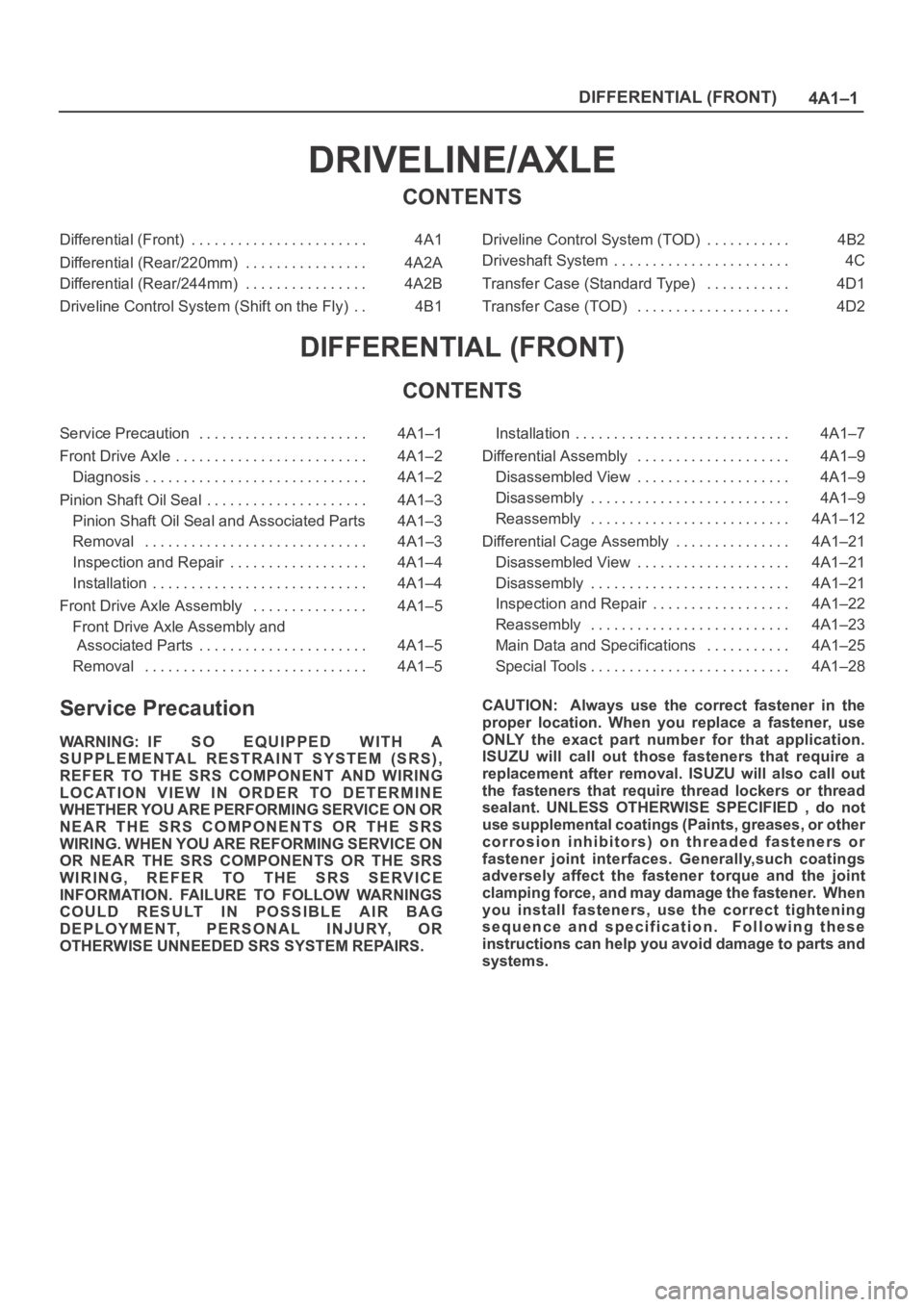
4A1–1 DIFFERENTIAL (FRONT)
DRIVELINE/AXLE
CONTENTS
Differential (Front) 4A1. . . . . . . . . . . . . . . . . . . . . . .
Differential (Rear/220mm) 4A2A. . . . . . . . . . . . . . . .
Differential (Rear/244mm) 4A2B. . . . . . . . . . . . . . . .
Driveline Control System (Shift on the Fly) 4B1. . Driveline Control System (TOD) 4B2. . . . . . . . . . .
Driveshaft System 4C. . . . . . . . . . . . . . . . . . . . . . .
Transfer Case (Standard Type) 4D1. . . . . . . . . . .
Transfer Case (TOD) 4D2. . . . . . . . . . . . . . . . . . . .
DIFFERENTIAL (FRONT)
CONTENTS
Service Precaution 4A1–1. . . . . . . . . . . . . . . . . . . . . .
Front Drive Axle 4A1–2. . . . . . . . . . . . . . . . . . . . . . . . .
Diagnosis 4A1–2. . . . . . . . . . . . . . . . . . . . . . . . . . . . .
Pinion Shaft Oil Seal 4A1–3. . . . . . . . . . . . . . . . . . . . .
Pinion Shaft Oil Seal and Associated Parts 4A1–3
Removal 4A1–3. . . . . . . . . . . . . . . . . . . . . . . . . . . . .
Inspection and Repair 4A1–4. . . . . . . . . . . . . . . . . .
Installation 4A1–4. . . . . . . . . . . . . . . . . . . . . . . . . . . .
Front Drive Axle Assembly 4A1–5. . . . . . . . . . . . . . .
Front Drive Axle Assembly and
Associated Parts 4A1–5. . . . . . . . . . . . . . . . . . . . . .
Removal 4A1–5. . . . . . . . . . . . . . . . . . . . . . . . . . . . . Installation 4A1–7. . . . . . . . . . . . . . . . . . . . . . . . . . . .
Differential Assembly 4A1–9. . . . . . . . . . . . . . . . . . . .
Disassembled View 4A1–9. . . . . . . . . . . . . . . . . . . .
Disassembly 4A1–9. . . . . . . . . . . . . . . . . . . . . . . . . .
Reassembly 4A1–12. . . . . . . . . . . . . . . . . . . . . . . . . .
Differential Cage Assembly 4A1–21. . . . . . . . . . . . . . .
Disassembled View 4A1–21. . . . . . . . . . . . . . . . . . . .
Disassembly 4A1–21. . . . . . . . . . . . . . . . . . . . . . . . . .
Inspection and Repair 4A1–22. . . . . . . . . . . . . . . . . .
Reassembly 4A1–23. . . . . . . . . . . . . . . . . . . . . . . . . .
Main Data and Specifications 4A1–25. . . . . . . . . . .
Special Tools 4A1–28. . . . . . . . . . . . . . . . . . . . . . . . . .
Service Precaution
WARNING: IF SO EQUIPPED WITH A
SUPPLEMENTAL RESTRAINT SYSTEM (SRS),
REFER TO THE SRS COMPONENT AND WIRING
LOCATION VIEW IN ORDER TO DETERMINE
WHETHER YOU ARE PERFORMING SERVICE ON OR
NEAR THE SRS COMPONENTS OR THE SRS
WIRING. WHEN YOU ARE REFORMING SERVICE ON
OR NEAR THE SRS COMPONENTS OR THE SRS
WIRING, REFER TO THE SRS SERVICE
INFORMATION. FAILURE TO FOLLOW WARNINGS
COULD RESULT IN POSSIBLE AIR BAG
DEPLOYMENT, PERSONAL INJURY, OR
OTHERWISE UNNEEDED SRS SYSTEM REPAIRS.CAUTION: Always use the correct fastener in the
proper location. When you replace a fastener, use
ONLY the exact part number for that application.
ISUZU will call out those fasteners that require a
replacement after removal. ISUZU will also call out
the fasteners that require thread lockers or thread
sealant. UNLESS OTHERWISE SPECIFIED , do not
use supplemental coatings (Paints, greases, or other
corrosion inhibitors) on threaded fasteners or
fastener joint interfaces. Generally,such coatings
adversely affect the fastener torque and the joint
clamping force, and may damage the fastener. When
you install fasteners, use the correct tightening
sequence and specification. Following these
instructions can help you avoid damage to parts and
systems.
Page 468 of 6000
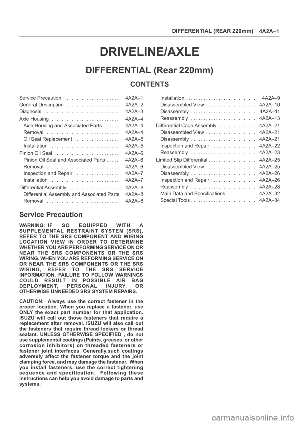
DIFFERENTIAL (REAR 220mm)
4A2A–1
DRIVELINE/AXLE
DIFFERENTIAL (Rear 220mm)
CONTENTS
Service Precaution 4A2A–1. . . . . . . . . . . . . . . . . . . . . .
General Description 4A2A–2. . . . . . . . . . . . . . . . . . . . .
Diagnosis 4A2A–3. . . . . . . . . . . . . . . . . . . . . . . . . . . . . .
Axle Housing 4A2A–4. . . . . . . . . . . . . . . . . . . . . . . . . . .
Axle Housing and Associated Parts 4A2A–4. . . . . .
Removal 4A2A–4. . . . . . . . . . . . . . . . . . . . . . . . . . . . .
Oil Seal Replacement 4A2A–5. . . . . . . . . . . . . . . . . .
Installation 4A2A–5. . . . . . . . . . . . . . . . . . . . . . . . . . . .
Pinion Oil Seal 4A2A–6. . . . . . . . . . . . . . . . . . . . . . . . . .
Pinion Oil Seal and Associated Parts 4A2A–6. . . . .
Removal 4A2A–6. . . . . . . . . . . . . . . . . . . . . . . . . . . . .
Inspection and Repair 4A2A–7. . . . . . . . . . . . . . . . . .
Installation 4A2A–7. . . . . . . . . . . . . . . . . . . . . . . . . . . .
Differential Assembly 4A2A–8. . . . . . . . . . . . . . . . . . . .
Differential Assembly and Associated Parts 4A2A–8
Removal 4A2A–8. . . . . . . . . . . . . . . . . . . . . . . . . . . . . Installation 4A2A–9. . . . . . . . . . . . . . . . . . . . . . . . . . . .
Disassembled View 4A2A–10. . . . . . . . . . . . . . . . . . . .
Disassembly 4A2A–11. . . . . . . . . . . . . . . . . . . . . . . . . .
Reassembly 4A2A–13. . . . . . . . . . . . . . . . . . . . . . . . . .
Differential Cage Assembly 4A2A–21. . . . . . . . . . . . . . .
Disassembled View 4A2A–21. . . . . . . . . . . . . . . . . . . .
Disassembly 4A2A–21. . . . . . . . . . . . . . . . . . . . . . . . . .
Inspection and Repair 4A2A–22. . . . . . . . . . . . . . . . . .
Reassembly 4A2A–23. . . . . . . . . . . . . . . . . . . . . . . . . .
Limited Slip Differential 4A2A–25. . . . . . . . . . . . . . . . . . .
Disassembled View 4A2A–25. . . . . . . . . . . . . . . . . . . .
Disassembly 4A2A–26. . . . . . . . . . . . . . . . . . . . . . . . . .
Inspection and Repair 4A2A–26. . . . . . . . . . . . . . . . . .
Reassembly 4A2A–28. . . . . . . . . . . . . . . . . . . . . . . . . .
Main Data and Specifications 4A2A–32. . . . . . . . . . .
Special Tools 4A2A–34. . . . . . . . . . . . . . . . . . . . . . . . . .
Service Precaution
WARNING: IF SO EQUIPPED WITH A
SUPPLEMENTAL RESTRAINT SYSTEM (SRS),
REFER TO THE SRS COMPONENT AND WIRING
LOCATION VIEW IN ORDER TO DETERMINE
WHETHER YOU ARE PERFORMING SERVICE ON OR
NEAR THE SRS COMPONENTS OR THE SRS
WIRING. WHEN YOU ARE REFORMING SERVICE ON
OR NEAR THE SRS COMPONENTS OR THE SRS
WIRING, REFER TO THE SRS SERVICE
INFORMATION. FAILURE TO FOLLOW WARNINGS
COULD RESULT IN POSSIBLE AIR BAG
DEPLOYMENT, PERSONAL INJURY, OR
OTHERWISE UNNEEDED SRS SYSTEM REPAIRS.
CAUTION: Always use the correct fastener in the
proper location. When you replace a fastener, use
ONLY the exact part number for that application.
ISUZU will call out those fasteners that require a
replacement after removal. ISUZU will also call out
the fasteners that require thread lockers or thread
sealant. UNLESS OTHERWISE SPECIFIED , do not
use supplemental coatings (Paints, greases, or other
corrosion inhibitors) on threaded fasteners or
fastener joint interfaces. Generally,such coatings
adversely affect the fastener torque and the joint
c l a m p i n g f o r c e , a n d m a y d a m a g e t h e f a s t e n e r. W h e n
you install fasteners, use the correct tightening
sequence and specification. Following these
instructions can help you avoid damage to parts and
systems.
Page 504 of 6000

DIFFERENTIAL (REAR 244mm)
4A2B–1
DRIVELINE/AXLE
DIFFERENTIAL (REAR 244mm)
CONTENTS
Service Precaution 4A2B–1. . . . . . . . . . . . . . . . . . . . . .
General Description 4A2B–2. . . . . . . . . . . . . . . . . . . . .
Diagnosis 4A2B–3. . . . . . . . . . . . . . . . . . . . . . . . . . . . . .
Axle Housing 4A2B–4. . . . . . . . . . . . . . . . . . . . . . . . . . .
Axle Housing and Associated Parts 4A2B–4. . . . . .
Removal 4A2B–4. . . . . . . . . . . . . . . . . . . . . . . . . . . . .
Oil Seal Replacement 4A2B–5. . . . . . . . . . . . . . . . . .
Installation 4A2B–5. . . . . . . . . . . . . . . . . . . . . . . . . . . .
Pinion Oil Seal 4A2B–6. . . . . . . . . . . . . . . . . . . . . . . . . .
Pinion Oil Seal and Associated Parts 4A2B–6. . . . .
Removal 4A2B–6. . . . . . . . . . . . . . . . . . . . . . . . . . . . .
Inspection and Repair 4A2B–7. . . . . . . . . . . . . . . . . .
Installation 4A2B–7. . . . . . . . . . . . . . . . . . . . . . . . . . . .
Differential Assembly 4A2B–8. . . . . . . . . . . . . . . . . . . .
Differential Assembly and Associated Parts 4A2B–8
Removal 4A2B–8. . . . . . . . . . . . . . . . . . . . . . . . . . . . . Installation 4A2B–9. . . . . . . . . . . . . . . . . . . . . . . . . . . .
Disassembled View 4A2B–10. . . . . . . . . . . . . . . . . . . .
Disassembly 4A2B–11. . . . . . . . . . . . . . . . . . . . . . . . . .
Reassembly 4A2B–13. . . . . . . . . . . . . . . . . . . . . . . . . .
Differential Cage Assembly 4A2B–20. . . . . . . . . . . . . . .
Disassembled View 4A2B–20. . . . . . . . . . . . . . . . . . . .
Disassembly 4A2B–21. . . . . . . . . . . . . . . . . . . . . . . . . .
Inspection and Repair 4A2B–21. . . . . . . . . . . . . . . . . .
Reassembly 4A2B–21. . . . . . . . . . . . . . . . . . . . . . . . . .
Locking Differential Assembly 4A2B–23. . . . . . . . . . . . .
Disassembled View 4A2B–23. . . . . . . . . . . . . . . . . . . .
Disassembly 4A2B–23. . . . . . . . . . . . . . . . . . . . . . . . . .
Inspection and Repair 4A2B–25. . . . . . . . . . . . . . . . . .
Reassembly 4A2B–25. . . . . . . . . . . . . . . . . . . . . . . . . .
Main Data and Specifications 4A2B–27. . . . . . . . . . . . .
Special Tools 4A2B–29. . . . . . . . . . . . . . . . . . . . . . . . . . .
Service Precaution
WARNING: IF SO EQUIPPED WITH A
SUPPLEMENTAL RESTRAINT SYSTEM (SRS),
REFER TO THE SRS COMPONENT AND WIRING
LOCATION VIEW IN ORDER TO DETERMINE
WHETHER YOU ARE PERFORMING SERVICE ON OR
NEAR THE SRS COMPONENTS OR THE SRS
WIRING. WHEN YOU ARE REFORMING SERVICE ON
OR NEAR THE SRS COMPONENTS OR THE SRS
WIRING, REFER TO THE SRS SERVICE
INFORMATION. FAILURE TO FOLLOW WARNINGS
COULD RESULT IN POSSIBLE AIR BAG
DEPLOYMENT, PERSONAL INJURY, OR
OTHERWISE UNNEEDED SRS SYSTEM REPAIRS.
CAUTION: Always use the correct fastener in the
proper location. When you replace a fastener, use
ONLY the exact part number for that application.
ISUZU will call out those fasteners that require a
replacement after removal. ISUZU will also call out
the fasteners that require thread lockers or thread
sealant. UNLESS OTHERWISE SPECIFIED , do not
use supplemental coatings (Paints, greases, or other
corrosion inhibitors) on threaded fasteners or
fastener joint interfaces. Generally,such coatings
adversely affect the fastener torque and the joint
c l a m p i n g f o r c e , a n d m a y d a m a g e t h e f a s t e n e r. W h e n
you install fasteners, use the correct tightening
sequence and specification. Following these
instructions can help you avoid damage to parts and
systems.
Page 534 of 6000
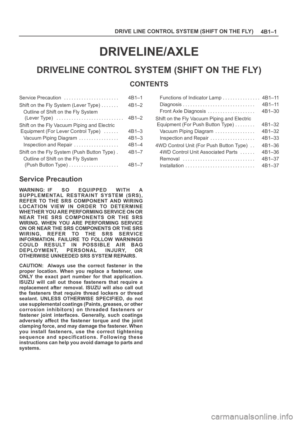
4B1–1 DRIVE LINE CONTROL SYSTEM (SHIFT ON THE FLY)
DRIVELINE/AXLE
DRIVELINE CONTROL SYSTEM (SHIFT ON THE FLY)
CONTENTS
Service Precaution 4B1–1. . . . . . . . . . . . . . . . . . . . . .
Shift on the Fly System (Lever Type) 4B1–2. . . . . . .
Outline of Shift on the Fly System
(Lever Type) 4B1–2. . . . . . . . . . . . . . . . . . . . . . . . . . .
Shift on the Fly Vacuum Piping and Electric
Equipment (For Lever Control Type) 4B1–3. . . . . .
Vacuum Piping Diagram 4B1–3. . . . . . . . . . . . . . . .
Inspection and Repair 4B1–4. . . . . . . . . . . . . . . . . .
Shift on the Fly System (Push Button Type) 4B1–7.
Outline of Shift on the Fly System
(Push Button Type) 4B1–7. . . . . . . . . . . . . . . . . . . . Functions of Indicator Lamp 4B1–11. . . . . . . . . . . . . . .
Diagnosis 4B1–11. . . . . . . . . . . . . . . . . . . . . . . . . . . . .
Front Axle Diagnosis 4B1–30. . . . . . . . . . . . . . . . . . .
Shift on the Fly Vacuum Piping and Electric
Equipment (For Push Button Type) 4B1–32. . . . . . . .
Vacuum Piping Diagram 4B1–32. . . . . . . . . . . . . . . .
Inspection and Repair 4B1–33. . . . . . . . . . . . . . . . . .
4WD Control Unit (For Push Button Type) 4B1–36. .
4WD Control Unit Associated Parts 4B1–36. . . . . .
Removal 4B1–37. . . . . . . . . . . . . . . . . . . . . . . . . . . . .
Installation 4B1–37. . . . . . . . . . . . . . . . . . . . . . . . . . . .
Service Precaution
WARNING: IF SO EQUIPPED WITH A
SUPPLEMENTAL RESTRAINT SYSTEM (SRS),
REFER TO THE SRS COMPONENT AND WIRING
LOCATION VIEW IN ORDER TO DETERMINE
WHETHER YOU ARE PERFORMING SERVICE ON OR
NEAR THE SRS COMPONENTS OR THE SRS
WIRING. WHEN YOU ARE PERFORMING SERVICE
ON OR NEAR THE SRS COMPONENTS OR THE SRS
WIRING, REFER TO THE SRS SERVICE
INFORMATION. FAILURE TO FOLLOW WARNINGS
COULD RESULT IN POSSIBLE AIR BAG
DEPLOYMENT, PERSONAL INJURY, OR
OTHERWISE UNNEEDED SRS SYSTEM REPAIRS.
CAUTION: Always use the correct fastener in the
proper location. When you replace a fastener, use
ONLY the exact part number for that application.
ISUZU will call out those fasteners that require a
replacement after removal. ISUZU will also call out
the fasteners that require thread lockers or thread
sealant. UNLESS OTHERWISE SPECIFIED, do not
use supplemental coatings (Paints, greases, or other
corrosion inhibitors) on threaded fasteners or
fastener joint interfaces. Generally, such coatings
adversely affect the fastener torque and the joint
clamping force, and may damage the fastener. When
you install fasteners, use the correct tightening
sequence and specifications. Following these
instructions can help you avoid damage to parts and
systems.
Page 543 of 6000
4B1–10
DRIVE LINE CONTROL SYSTEM (SHIFT ON THE FLY)
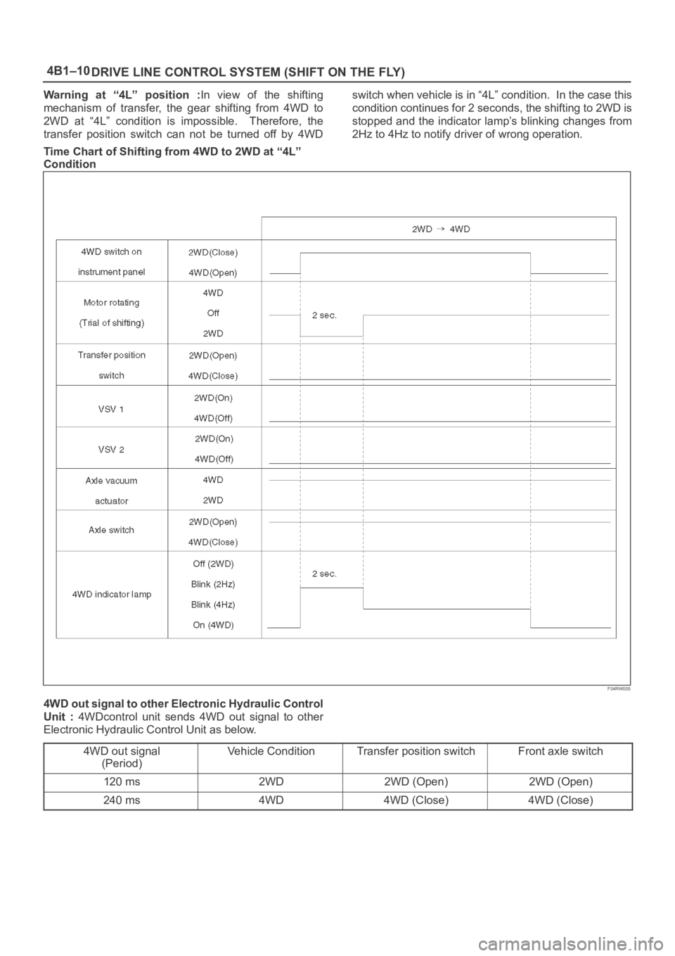
Warning at “4L” position :In view of the shifting
mechanism of transfer, the gear shifting from 4WD to
2WD at “4L” condition is impossible. Therefore, the
transfer position switch can not be turned off by 4WDswitch when vehicle is in “4L” condition. In the case this
condition continues for 2 seconds, the shifting to 2WD is
stopped and the indicator lamp’s blinking changes from
2Hz to 4Hz to notify driver of wrong operation.
Time Chart of Shifting from 4WD to 2WD at “4L”
Condition
F04RW005
4WD out signal to other Electronic Hydraulic Control
Unit : 4WDcontrol unit sends 4WD out signal to other
Electronic Hydraulic Control Unit as below.
4WD out signal
(Period)
Vehicle ConditionTransfer position switchFront axle switch
120 ms2WD2WD (Open)2WD (Open)
240 ms4WD4WD (Close)4WD (Close)
Page 572 of 6000
4B2–1 DRIVE LINE CONTROL SYSTEM (TOD)
DRIVELINE/AXLE
DRIVELINE CONTROL SYSTEM (TOD)
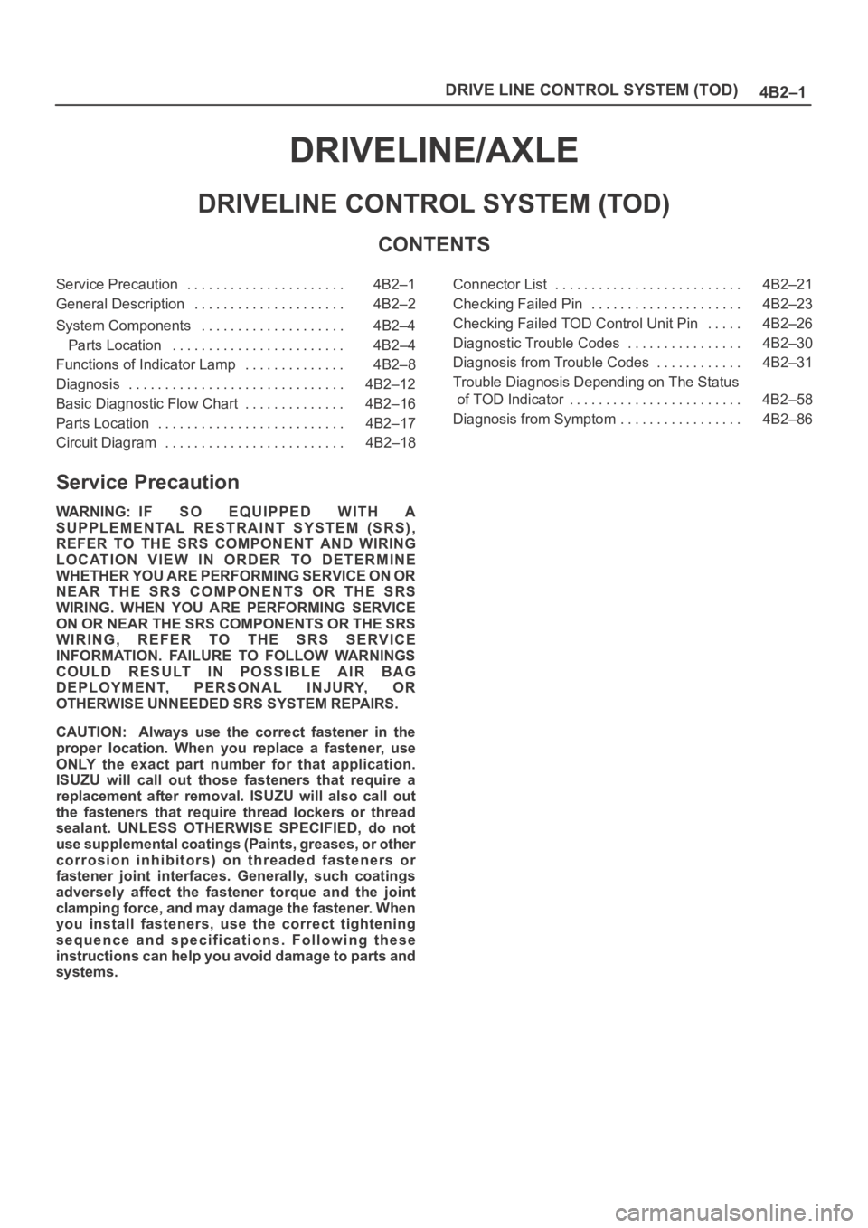
CONTENTS
Service Precaution 4B2–1. . . . . . . . . . . . . . . . . . . . . .
General Description 4B2–2. . . . . . . . . . . . . . . . . . . . .
System Components 4B2–4. . . . . . . . . . . . . . . . . . . .
Parts Location 4B2–4. . . . . . . . . . . . . . . . . . . . . . . .
Functions of Indicator Lamp 4B2–8. . . . . . . . . . . . . .
Diagnosis 4B2–12. . . . . . . . . . . . . . . . . . . . . . . . . . . . . .
Basic Diagnostic Flow Chart 4B2–16. . . . . . . . . . . . . .
Parts Location 4B2–17. . . . . . . . . . . . . . . . . . . . . . . . . .
Circuit Diagram 4B2–18. . . . . . . . . . . . . . . . . . . . . . . . . Connector List 4B2–21. . . . . . . . . . . . . . . . . . . . . . . . . .
Checking Failed Pin 4B2–23. . . . . . . . . . . . . . . . . . . . .
Checking Failed TOD Control Unit Pin 4B2–26. . . . .
Diagnostic Trouble Codes 4B2–30. . . . . . . . . . . . . . . .
Diagnosis from Trouble Codes 4B2–31. . . . . . . . . . . .
Trouble Diagnosis Depending on The Status
of TOD Indicator 4B2–58. . . . . . . . . . . . . . . . . . . . . . . .
Diagnosis from Symptom 4B2–86. . . . . . . . . . . . . . . . .
Service Precaution
WARNING: IF SO EQUIPPED WITH A
SUPPLEMENTAL RESTRAINT SYSTEM (SRS),
REFER TO THE SRS COMPONENT AND WIRING
LOCATION VIEW IN ORDER TO DETERMINE
WHETHER YOU ARE PERFORMING SERVICE ON OR
NEAR THE SRS COMPONENTS OR THE SRS
WIRING. WHEN YOU ARE PERFORMING SERVICE
ON OR NEAR THE SRS COMPONENTS OR THE SRS
WIRING, REFER TO THE SRS SERVICE
INFORMATION. FAILURE TO FOLLOW WARNINGS
COULD RESULT IN POSSIBLE AIR BAG
DEPLOYMENT, PERSONAL INJURY, OR
OTHERWISE UNNEEDED SRS SYSTEM REPAIRS.
CAUTION: Always use the correct fastener in the
proper location. When you replace a fastener, use
ONLY the exact part number for that application.
ISUZU will call out those fasteners that require a
replacement after removal. ISUZU will also call out
the fasteners that require thread lockers or thread
sealant. UNLESS OTHERWISE SPECIFIED, do not
use supplemental coatings (Paints, greases, or other
corrosion inhibitors) on threaded fasteners or
fastener joint interfaces. Generally, such coatings
adversely affect the fastener torque and the joint
clamping force, and may damage the fastener. When
you install fasteners, use the correct tightening
sequence and specifications. Following these
instructions can help you avoid damage to parts and
systems.
Page 595 of 6000
DRIVE LINE CONTROL SYSTEM (TOD) 4B2–24
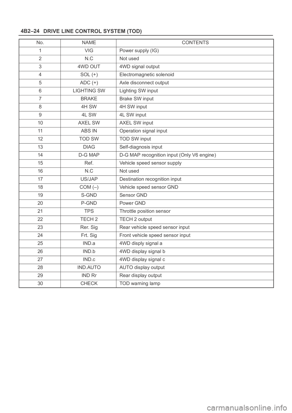
No.NAMECONTENTS
1VIGPower supply (IG)
2N.CNot used
34WD OUT4WD signal output
4SOL (+)Electromagnetic solenoid
5ADC (+)Axle disconnect output
6LIGHTING SWLighting SW input
7BRAKEBrake SW input
84H SW4H SW input
94L SW4L SW input
10AXEL SWAXEL SW input
11ABS INOperation signal input
12TOD SWTOD SW input
13DIAGSelf-diagnosis input
14D-G MAPD-G MAP recognition input (Only V6 engine)
15Ref.Vehicle speed sensor supply
16N.CNot used
17US/JAPDestination recognition input
18COM (–)Vehicle speed sensor GND
19S-GNDSensor GND
20P-GNDPower GND
21TPSThrottle position sensor
22TECH 2TECH 2 output
23Rer. SigRear vehicle speed sensor input
24Frt. SigFront vehicle speed sensor input
25IND.a4WD disply signal a
26IND.b4WD display signal b
27IND.c4WD display signal c
28IND.AUTOAUTO display output
29IND RrRear display output
30CHECKTOD warning lamp
Page 657 of 6000
DRIVE LINE CONTROL SYSTEM (TOD) 4B2–86
Diagnosis from Symptom
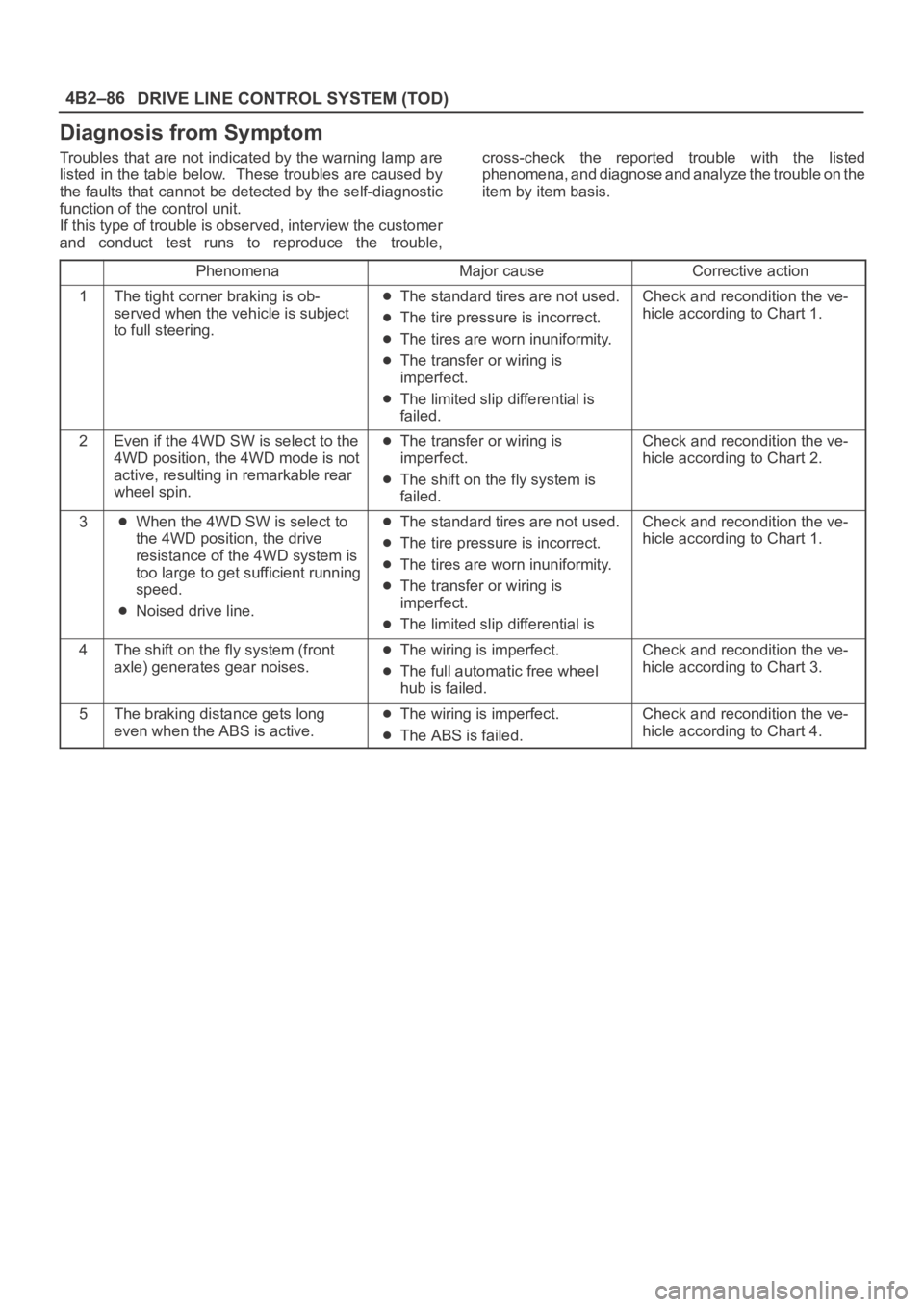
Troubles that are not indicated by the warning lamp are
listed in the table below. These troubles are caused by
the faults that cannot be detected by the self-diagnostic
function of the control unit.
If this type of trouble is observed, interview the customer
and conduct test runs to reproduce the trouble,cross-check the reported trouble with the listed
phenomena, and diagnose and analyze the trouble on the
item by item basis.
PhenomenaMajor causeCorrective action
1The tight corner braking is ob-
served when the vehicle is subject
to full steering.The standard tires are not used.
The tire pressure is incorrect.
The tires are worn inuniformity.
The transfer or wiring is
imperfect.
The limited slip differential is
failed.
Check and recondition the ve-
hicle according to Chart 1.
2Even if the 4WD SW is select to the
4WD position, the 4WD mode is not
active, resulting in remarkable rear
wheel spin.The transfer or wiring is
imperfect.
The shift on the fly system is
failed.
Check and recondition the ve-
hicle according to Chart 2.
3When the 4WD SW is select to
the 4WD position, the drive
resistance of the 4WD system is
too large to get sufficient running
speed.
Noised drive line.
The standard tires are not used.
The tire pressure is incorrect.
The tires are worn inuniformity.
The transfer or wiring is
imperfect.
The limited slip differential is
Check and recondition the ve-
hicle according to Chart 1.
4The shift on the fly system (front
axle) generates gear noises.The wiring is imperfect.
The full automatic free wheel
hub is failed.
Check and recondition the ve-
hicle according to Chart 3.
5The braking distance gets long
even when the ABS is active.The wiring is imperfect.
The ABS is failed.
Check and recondition the ve-
hicle according to Chart 4.