warning OPEL FRONTERA 1998 Owner's Guide
[x] Cancel search | Manufacturer: OPEL, Model Year: 1998, Model line: FRONTERA, Model: OPEL FRONTERA 1998Pages: 6000, PDF Size: 97 MB
Page 873 of 6000

5B–1 ANTI–LOCK BRAKE SYSTEM
BRAKES
ANTI-LOCK BRAKE SYSTEM
CONTENTS
Service Precaution 5B–1. . . . . . . . . . . . . . . . . . . . . .
Electronic Hydraulic Control Unit 5B–2. . . . . . . . . .
Electronic Hydraulic Control Unit and
Associated Parts 5B–2. . . . . . . . . . . . . . . . . . . . . .
Removal 5B–2. . . . . . . . . . . . . . . . . . . . . . . . . . . . .
Installation 5B–2. . . . . . . . . . . . . . . . . . . . . . . . . . . .
G-Sensor 5B–3. . . . . . . . . . . . . . . . . . . . . . . . . . . . . .
Removal 5B–3. . . . . . . . . . . . . . . . . . . . . . . . . . . . .
Inspection and Repair 5B–3. . . . . . . . . . . . . . . . . .
Installation 5B–3. . . . . . . . . . . . . . . . . . . . . . . . . . . .
Front Wheel Speed Sensor 5B–4. . . . . . . . . . . . . . . Front Wheel Speed Sensor and
Associated Parts 5B–4. . . . . . . . . . . . . . . . . . . . . .
Removal 5B–4. . . . . . . . . . . . . . . . . . . . . . . . . . . . .
Inspection and Repair 5B–5. . . . . . . . . . . . . . . . . .
Installation 5B–5. . . . . . . . . . . . . . . . . . . . . . . . . . . .
Rear Wheel Speed Sensor 5B–6. . . . . . . . . . . . . . .
Rear Wheel Speed Sensor and
Associated Parts 5B–6. . . . . . . . . . . . . . . . . . . . . .
Removal 5B–6. . . . . . . . . . . . . . . . . . . . . . . . . . . . .
Inspection and Repair 5B–6. . . . . . . . . . . . . . . . . .
Installation 5B–6. . . . . . . . . . . . . . . . . . . . . . . . . . . .
Service Precaution
WARNING: IF SO EQUIPPED WITH A
SUPPLEMENTAL RESTRAINT SYSTEM(SRS),
REFER TO THE SRS COMPONENT AND WIRING
LOCATION VIEW IN ORDER TO DETERMINE
WHETHER YOU ARE PERFORMING SERVICE ON OR
NEAR THE SRS COMPONENTS OR THE SRS
WIRING. WHEN YOU ARE PERFORMING SERVICE
ON OR NEAR THE SRS COMPONENTS OR THE SRS
WIRING, REFER TO THE SRS SERVICE
INFORMATION. FAILURE TO FOLLOW WARNINGS
COULD RESULT IN POSSIBLE AIR BAG
DEPLOYMENT, PERSONAL INJURY, OR
OTHERWISE UNNEEDED SRS SYSTEM REPAIRS.
CAUTION: Always use the correct fastener in the
proper location. When you replace a fastener, use
ONLY the exact part number for that application.
ISUZU will call out those fasteners that require a
replacement after removal. ISUZU will also call out
the fasteners that require thread lockers or thread
sealant. UNLESS OTHERWISE SPECIFIED, do not
use supplemental coatings (Paints, greases, or other
corrosion inhibitors) on threaded fasteners or
fastener joint interfaces. Generally, such coatings
adversely affect the fastener torque and the joint
clamping force, and may damage the fastener. When
you install fasteners, use the correct tightening
sequence and specifications. Following these
instructions can help you avoid damage to parts and
systems.CAUTION: Replace all components included in
repair kits used to service this system. Lubricate
rubber parts with clean, fresh brake fluid to ease
assembly. Do not use shop air with in–line
lubricators on brake parts, as damage to rubber
components may result. If any hydraulic component
is removed or brake line disconnected, it may be
necessary to bleed part or all of the brake system.
NOTE: The use of rubber hoses or parts other than those
furnished specifically for the Anti–lock Brake System may
lead to functional problems requiring major overhaul.
Page 958 of 6000

6A–2
ENGINE MECHANICAL
Piston and Connecting Rod 6A–77. . . . . . . . . . . . . . .
Piston, Connecting Rod and Associate
Parts 6A–77. . . . . . . . . . . . . . . . . . . . . . . . . . . . . . . .
Disassembly 6A–77. . . . . . . . . . . . . . . . . . . . . . . . . .
Inspection and Repair 6A–78. . . . . . . . . . . . . . . . . .
Reassembly 6A–82. . . . . . . . . . . . . . . . . . . . . . . . . .
Cylinder Block 6A–85. . . . . . . . . . . . . . . . . . . . . . . . . .
Cylinder Block and Associated Parts 6A–85. . . . .
Disassembly 6A–85. . . . . . . . . . . . . . . . . . . . . . . . . .
Inspection and Repair 6A–86. . . . . . . . . . . . . . . . . .
Reassembly 6A–87. . . . . . . . . . . . . . . . . . . . . . . . . .
Main Data and Specification 6A–90. . . . . . . . . . . . . .
Special Tool 6A–96. . . . . . . . . . . . . . . . . . . . . . . . . . . .
Service Precaution
WARNING: IF SO EQUIPPED WITH A
SUPPLEMENTAL RESTRAINT SYSTEM (SRS),
REFER TO THE SRS COMPONENT AND WIRING
LOCATION VIEW IN ORDER TO DETERMINE
WHETHER YOU ARE PERFORMING SERVICE ON OR
NEAR THE SRS COMPONENTS OR THE SRS
WIRING. WHEN YOU ARE PERFORMING SERVICE
ON OR NEAR THE SRS COMPONENTS OR THE SRS
WIRING, REFER TO THE SRS SERVICE
INFORMATION. FAILURE TO FOLLOW WARNINGS
COULD RESULT IN POSSIBLE AIR BAG
DEPLOYMENT, PERSONAL INJURY, OR
OTHERWISE UNNEEDED SRS SYSTEM REPAIRS.
CAUTION: Always use the correct fastener in the
proper location. When you replace a fastener, use
ONLY the exact part number for that application.
ISUZU will call out those fasteners that require a
replacement after removal. ISUZU will also call out
the fasteners that require thread lockers or thread
sealant. UNLESS OTHERWISE SPECIFIED, do not
use supplemental coatings (Paints, greases, or other
corrosion inhibitors) on threaded fasteners or
fastener joint interfaces. Generally, such coatings
adversely affect the fastener torque and the joint
clamping force, and may damage the fastener. When
you install fasteners, use the correct tightening
sequence and specifications. Following these
instructions can help you avoid damage to parts and
systems.
Page 1054 of 6000

ENGINE COOLING6B–1
ENGINE
ENGINE COOLING
CONTENTS
Service Precaution 6B–1. . . . . . . . . . . . . . . . . . . . . .
General Description 6B–2. . . . . . . . . . . . . . . . . . . . .
Diagnosis 6B–5. . . . . . . . . . . . . . . . . . . . . . . . . . . . . .
Draining and Refilling Cooling System 6B–6. . . . .
Water Pump 6B–7. . . . . . . . . . . . . . . . . . . . . . . . . . . .
Water Pump and Associated Parts 6B–7. . . . . . .
Removal 6B–7. . . . . . . . . . . . . . . . . . . . . . . . . . . . .
Inspection 6B–7. . . . . . . . . . . . . . . . . . . . . . . . . . . .
Installation 6B–7. . . . . . . . . . . . . . . . . . . . . . . . . . . .
Thermostat 6B–8. . . . . . . . . . . . . . . . . . . . . . . . . . . . .
Thermostat and Associated Parts 6B–8. . . . . . . .
Removal 6B–8. . . . . . . . . . . . . . . . . . . . . . . . . . . . .
Inspection 6B–8. . . . . . . . . . . . . . . . . . . . . . . . . . . . Installation 6B–8. . . . . . . . . . . . . . . . . . . . . . . . . . . .
Radiator 6B–9. . . . . . . . . . . . . . . . . . . . . . . . . . . . . . .
Radiator and Associated Parts 6B–9. . . . . . . . . .
Removal 6B–9. . . . . . . . . . . . . . . . . . . . . . . . . . . . .
Inspection 6B–10. . . . . . . . . . . . . . . . . . . . . . . . . . . .
Installation 6B–11. . . . . . . . . . . . . . . . . . . . . . . . . . . .
Drive Belt and Cooling Fan 6B–12. . . . . . . . . . . . . . .
Drive Belt and Associated Parts 6B–12. . . . . . . . .
Inspection 6B–12. . . . . . . . . . . . . . . . . . . . . . . . . . . .
Installation 6B–12. . . . . . . . . . . . . . . . . . . . . . . . . . . .
Main Data and Specifications 6B–13. . . . . . . . . . . . .
Special Tool 6B–14. . . . . . . . . . . . . . . . . . . . . . . . . . . .
Service Precaution
WARNING: IF SO EQUIPPED WITH A
SUPPLEMENTAL RESTRAINT SYSTEM (SRS),
REFER TO THE SRS COMPONENT AND WIRING
LOCATION VIEW IN ORDER TO DETERMINE
WHETHER YOU ARE PERFORMING SERVICE ON OR
NEAR THE SRS COMPONENTS OR THE SRS
WIRING. WHEN YOU ARE PERFORMING SERVICE
ON OR NEAR THE SRS COMPONENTS OR THE SRS
WIRING, REFER TO THE SRS SERVICE
INFORMATION. FAILURE TO FOLLOW WARNINGS
COULD RESULT IN POSSIBLE AIR BAG
DEPLOYMENT, PERSONAL INJURY, OR
OTHERWISE UNNEEDED SRS SYSTEM REPAIRS.
CAUTION: Always use the correct fastener in the
proper location. When you replace a fastener, use
ONLY the exact part number for that application.
ISUZU will call out those fasteners that require a
replacement after removal. ISUZU will also call out
the fasteners that require thread lockers or thread
sealant. UNLESS OTHERWISE SPECIFIED, do not
use supplemental coatings (Paints, greases, or other
corrosion inhibitors) on threaded fasteners or
fastener joint interfaces. Generally, such coatings
adversely affect the fastener torque and the joint
clamping force, and may damage the fastener. When
you install fasteners, use the correct tightening
sequence and specifications. Following these
instructions can help you avoid damage to parts and
systems.
Page 1059 of 6000
6B–6
ENGINE COOLING
Draining and Refilling Cooling
System
Before draining the cooling system, inspect the system
and perform any necessary service to ensure that it is
clean, does not leak and is in proper working order. The
engine coolant (EC) level should be between the “MIN”
and “MAX” lines of reserve tank when the engine is cold.
If low, check for leakage and add EC up to the “MAX” line.
There should not be any excessive deposit of rust or
scales around the radiator cap or radiator filler hole, and
the EC should also be free from oil.
Replace the EC if excessively dirty.
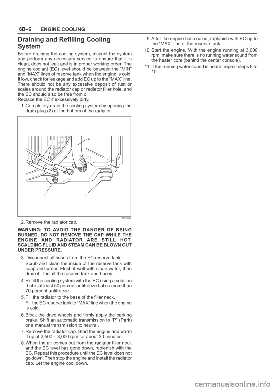
1. Completely drain the cooling system by opening the
drain plug (2) at the bottom of the radiator.
110RW002
2. Remove the radiator cap.
WARNING: TO AVOID THE DANGER OF BEING
BURNED, DO NOT REMOVE THE CAP WHILE THE
ENGINE AND RADIATOR ARE STILL HOT.
SCALDING FLUID AND STEAM CAN BE BLOWN OUT
UNDER PRESSURE.
3. Disconnect all hoses from the EC reserve tank.
Scrub and clean the inside of the reserve tank with
soap and water. Flush it well with clean water, then
drain it. Install the reserve tank and hoses.
4. Refill the cooling system with the EC using a solution
that is at least 50 percent antifreeze but no more than
70 percent antifreeze.
5. Fill the radiator to the base of the filler neck.
Fill the EC reserve tank to “MAX” line when the engine
is cold.
6. Block the drive wheels and firmly apply the parking
brake. Shift an automatic transmission to “P” (Park)
or a manual transmission to neutral.
7. Remove the radiator cap. Start the engine and warm
it up at 2,500
3,000 rpm for about 30 minutes.
8. When the air comes out from the radiator filler neck
and the EC level has gone down, replenish with the
EC. Repeat this procedure until the EC level does not
go down. Then stop the engine and install the radiator
cap. Let the engine cool down.9. After the engine has cooled, replenish with EC up to
the “MAX” line of the reserve tank.
10. Start the engine. With the engine running at 3,000
rpm, make sure there is no running water sound from
the heater core (behind the center console).
11. If the running water sound is heard, repeat steps 8 to
10.
Page 1064 of 6000
ENGINE COOLING6B–11
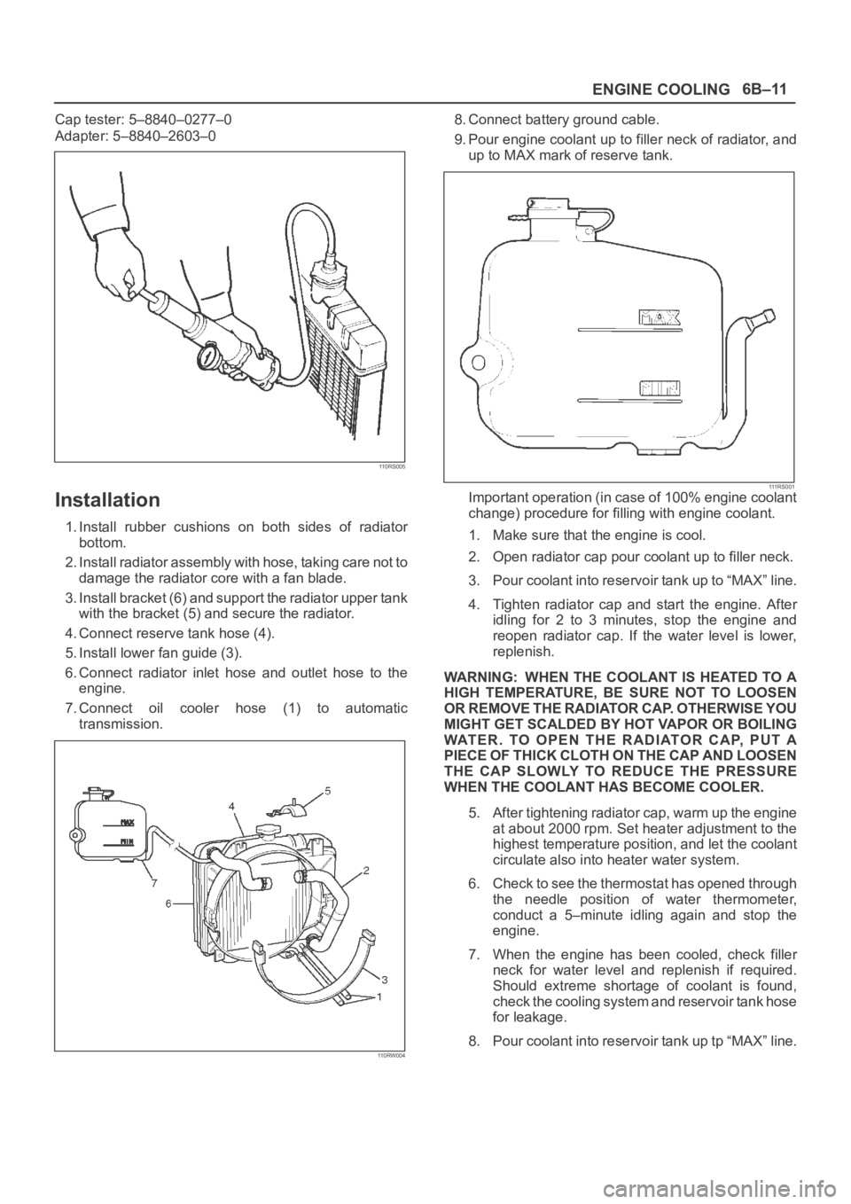
Cap tester: 5–8840–0277–0
Adapter: 5–8840–2603–0
110RS005
Installation
1. Install rubber cushions on both sides of radiator
bottom.
2. Install radiator assembly with hose, taking care not to
damage the radiator core with a fan blade.
3. Install bracket (6) and support the radiator upper tank
with the bracket (5) and secure the radiator.
4. Connect reserve tank hose (4).
5. Install lower fan guide (3).
6. Connect radiator inlet hose and outlet hose to the
engine.
7. Connect oil cooler hose (1) to automatic
transmission.
110RW004
8. Connect battery ground cable.
9. Pour engine coolant up to filler neck of radiator, and
up to MAX mark of reserve tank.
111 R S 0 0 1Important operation (in case of 100% engine coolant
change) procedure for filling with engine coolant.
1. Make sure that the engine is cool.
2. Open radiator cap pour coolant up to filler neck.
3. Pour coolant into reservoir tank up to “MAX” line.
4. Tighten radiator cap and start the engine. After
idling for 2 to 3 minutes, stop the engine and
reopen radiator cap. If the water level is lower,
replenish.
WARNING: WHEN THE COOLANT IS HEATED TO A
HIGH TEMPERATURE, BE SURE NOT TO LOOSEN
OR REMOVE THE RADIATOR CAP. OTHERWISE YOU
MIGHT GET SCALDED BY HOT VAPOR OR BOILING
WATER. TO OPEN THE RADIATOR CAP, PUT A
PIECE OF THICK CLOTH ON THE CAP AND LOOSEN
THE CAP SLOWLY TO REDUCE THE PRESSURE
WHEN THE COOLANT HAS BECOME COOLER.
5. After tightening radiator cap, warm up the engine
at about 2000 rpm. Set heater adjustment to the
highest temperature position, and let the coolant
circulate also into heater water system.
6. Check to see the thermostat has opened through
the needle position of water thermometer,
conduct a 5–minute idling again and stop the
engine.
7. When the engine has been cooled, check filler
neck for water level and replenish if required.
Should extreme shortage of coolant is found,
check the cooling system and reservoir tank hose
for leakage.
8. Pour coolant into reservoir tank up tp “MAX” line.
Page 1068 of 6000
6C–1
ENGINE FUEL
ENGINE
ENGINE FUEL
CONTENTS
Service Precaution 6C–1. . . . . . . . . . . . . . . . . . . . . .
General Description 6C–2. . . . . . . . . . . . . . . . . . . . .
Fuel Metering 6C–3. . . . . . . . . . . . . . . . . . . . . . . . . . .
Fuel Filter 6C–4. . . . . . . . . . . . . . . . . . . . . . . . . . . . . .
Fuel Filter and Associated Parts 6C–4. . . . . . . . .
Removal 6C–4. . . . . . . . . . . . . . . . . . . . . . . . . . . . .
Inspection 6C–4. . . . . . . . . . . . . . . . . . . . . . . . . . . .
Installation 6C–5. . . . . . . . . . . . . . . . . . . . . . . . . . . .
Inspection 6C–5. . . . . . . . . . . . . . . . . . . . . . . . . . . .
In–Tank Fuel Filter 6C–5. . . . . . . . . . . . . . . . . . . . .
Fuel Pump Flow Test 6C–5. . . . . . . . . . . . . . . . . . .
Fuel Pump 6C–6. . . . . . . . . . . . . . . . . . . . . . . . . . . . .
Fuel Pump and Associated Parts 6C–6. . . . . . . .
Removal 6C–6. . . . . . . . . . . . . . . . . . . . . . . . . . . . .
Installation 6C–6. . . . . . . . . . . . . . . . . . . . . . . . . . . .
Fuel Pump Relay 6C–7. . . . . . . . . . . . . . . . . . . . . . . .
General Description 6C–7. . . . . . . . . . . . . . . . . . . . .
Fuel Tank 6C–7. . . . . . . . . . . . . . . . . . . . . . . . . . . . . . Fuel Tank and Associated Parts 6C–7. . . . . . . . .
Removal 6C–7. . . . . . . . . . . . . . . . . . . . . . . . . . . . .
Installation 6C–8. . . . . . . . . . . . . . . . . . . . . . . . . . . .
Fuel Tube / Quick – Connect Fittings 6C–8. . . . . . .
Precautions 6C–8. . . . . . . . . . . . . . . . . . . . . . . . . . .
Cautions During Work 6C–8. . . . . . . . . . . . . . . . . .
Removal 6C–8. . . . . . . . . . . . . . . . . . . . . . . . . . . . .
Reuse of Quick–Connector 6C–10. . . . . . . . . . . . . . .
Assembling Advice 6C–10. . . . . . . . . . . . . . . . . . . . . .
Fuel Gauge Unit 6C–11. . . . . . . . . . . . . . . . . . . . . . . .
Fuel Gauge Unit and Associated Parts 6C–11. . .
Removal 6C–11. . . . . . . . . . . . . . . . . . . . . . . . . . . . .
Installation 6C–11. . . . . . . . . . . . . . . . . . . . . . . . . . . .
Fuel Filler Cap 6C–12. . . . . . . . . . . . . . . . . . . . . . . . . .
General Description 6C–12. . . . . . . . . . . . . . . . . . . . .
Inspection 6C–12. . . . . . . . . . . . . . . . . . . . . . . . . . . .
Main Data and Specifications 6C–12. . . . . . . . . . . . .
Service Precaution
WARNING: IF SO EQUIPPED WITH A
SUPPLEMENTAL RESTRAINT SYSTEM (SRS),
REFER TO THE SRS COMPONENT AND WIRING
LOCATION VIEW IN ORDER TO DETERMINE
WHETHER YOU ARE PERFORMING SERVICE ON OR
NEAR THE SRS COMPONENTS OR THE SRS
WIRING. WHEN YOU ARE PERFORMING SERVICE
ON OR NEAR THE SRS COMPONENTS OR THE SRS
WIRING, REFER TO THE SRS SERVICE
INFORMATION. FAILURE TO FOLLOW WARNINGS
COULD RESULT IN POSSIBLE AIR BAG
DEPLOYMENT, PERSONAL INJURY, OR
OTHERWISE UNNEEDED SRS SYSTEM REPAIRS.
CAUTION: Always use the correct fastener in the
proper location. When you replace a fastener, use
ONLY the exact part number for that application.
ISUZU will call out those fasteners that require a
replacement after removal. ISUZU will also call out
the fasteners that require thread lockers or thread
sealant. UNLESS OTHERWISE SPECIFIED, do not
use supplemental coatings (Paints, greases, or other
corrosion inhibitors) on threaded fasteners or
fastener joint interfaces. Generally, such coatings
adversely affect the fastener torque and the joint
clamping force, and may damage the fastener. When
you install fasteners, use the correct tightening
sequence and specifications. Following these
instructions can help you avoid damage to parts and
systems.
Page 1080 of 6000
ENGINE ELECTRICAL6D1–1
ENGINE
ENGINE ELECTRICAL
CONTENTS
Service Precaution 6D1–1. . . . . . . . . . . . . . . . . . . . . .
Battery 6D1–2. . . . . . . . . . . . . . . . . . . . . . . . . . . . . . . . .
General Description 6D1–2. . . . . . . . . . . . . . . . . . . .
Diagnosis 6D1–2. . . . . . . . . . . . . . . . . . . . . . . . . . . . .
Battery Charging 6D1–3. . . . . . . . . . . . . . . . . . . . . . Jump Starting 6D1–3. . . . . . . . . . . . . . . . . . . . . . . . .
Battery Removal 6D1–4. . . . . . . . . . . . . . . . . . . . . .
Battery Installation 6D1–4. . . . . . . . . . . . . . . . . . . . .
Main Data and Specifications 6D1–5. . . . . . . . . . .
Service Precaution
WARNING: IF SO EQUIPPED WITH A
SUPPLEMENTAL RESTRAINT SYSTEM (SRS),
REFER TO THE SRS COMPONENT AND WIRING
LOCATION VIEW IN ORDER TO DETERMINE
WHETHER YOU ARE PERFORMING SERVICE ON OR
NEAR THE SRS COMPONENTS OR THE SRS
WIRING. WHEN YOU ARE PERFORMING SERVICE
ON OR NEAR THE SRS COMPONENTS OR THE SRS
WIRING, REFER TO THE SRS SERVICE
INFORMATION. FAILURE TO FOLLOW WARNINGS
COULD RESULT IN POSSIBLE AIR BAG
DEPLOYMENT, PERSONAL INJURY, OR
OTHERWISE UNNEEDED SRS SYSTEM REPAIRS.
CAUTION: Always use the correct fastener in the
proper location. When you replace a fastener, use
ONLY the exact part number for that application.
ISUZU will call out those fasteners that require a
replacement after removal. ISUZU will also call out
the fasteners that require thread lockers or thread
sealant. UNLESS OTHERWISE SPECIFIED, do not
use supplemental coatings (Paints, greases, or other
corrosion inhibitors) on threaded fasteners or
fastener joint interfaces. Generally, such coatings
adversely affect the fastener torque and the joint
clamping force, and may damage the fastener. When
you install fasteners, use the correct tightening
sequence and specifications. Following these
instructions can help you avoid damage to parts and
systems.
Page 1082 of 6000
ENGINE ELECTRICAL6D1–3
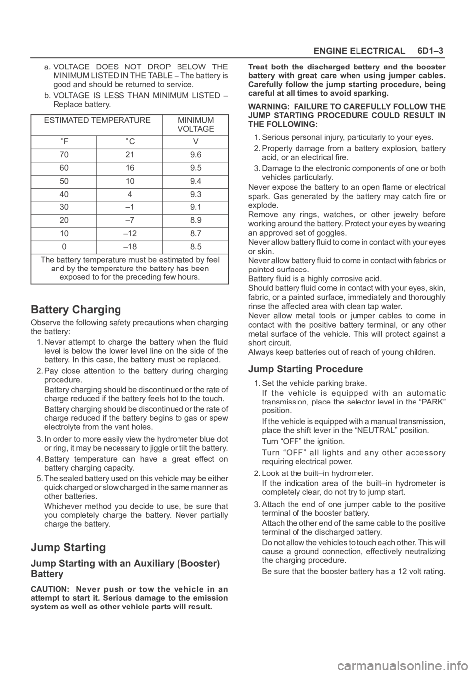
a. VOLTAGE DOES NOT DROP BELOW THE
MINIMUM LISTED IN THE TABLE – The battery is
good and should be returned to service.
b. VOLTAGE IS LESS THAN MINIMUM LISTED –
Replace battery.
ESTIMATED TEMPERATURE
MINIMUM
VOLTAGE
FCV
70219.6
60169.5
50109.4
4049.3
30–19.1
20–78.9
10–128.7
0–188.5
The battery temperature must be estimated by feel
and by the temperature the battery has been
exposed to for the preceding few hours.
Battery Charging
Observe the following safety precautions when charging
the battery:
1. Never attempt to charge the battery when the fluid
level is below the lower level line on the side of the
battery. In this case, the battery must be replaced.
2. Pay close attention to the battery during charging
procedure.
Battery charging should be discontinued or the rate of
charge reduced if the battery feels hot to the touch.
Battery charging should be discontinued or the rate of
charge reduced if the battery begins to gas or spew
electrolyte from the vent holes.
3. In order to more easily view the hydrometer blue dot
or ring, it may be necessary to jiggle or tilt the battery.
4. Battery temperature can have a great effect on
battery charging capacity.
5. The sealed battery used on this vehicle may be either
quick charged or slow charged in the same manner as
other batteries.
Whichever method you decide to use, be sure that
you completely charge the battery. Never partially
charge the battery.
Jump Starting
Jump Starting with an Auxiliary (Booster)
Battery
CAUTION: Never push or tow the vehicle in an
attempt to start it. Serious damage to the emission
system as well as other vehicle parts will result.Treat both the discharged battery and the booster
battery with great care when using jumper cables.
Carefully follow the jump starting procedure, being
careful at all times to avoid sparking.
WARNING: FAILURE TO CAREFULLY FOLLOW THE
JUMP STARTING PROCEDURE COULD RESULT IN
THE FOLLOWING:
1. Serious personal injury, particularly to your eyes.
2. Property damage from a battery explosion, battery
acid, or an electrical fire.
3. Damage to the electronic components of one or both
vehicles particularly.
Never expose the battery to an open flame or electrical
spark. Gas generated by the battery may catch fire or
explode.
Remove any rings, watches, or other jewelry before
working around the battery. Protect your eyes by wearing
an approved set of goggles.
Never allow battery fluid to come in contact with your eyes
or skin.
Never allow battery fluid to come in contact with fabrics or
painted surfaces.
Battery fluid is a highly corrosive acid.
Should battery fluid come in contact with your eyes, skin,
fabric, or a painted surface, immediately and thoroughly
rinse the affected area with clean tap water.
Never allow metal tools or jumper cables to come in
contact with the positive battery terminal, or any other
metal surface of the vehicle. This will protect against a
short circuit.
Always keep batteries out of reach of young children.
Jump Starting Procedure
1. Set the vehicle parking brake.
If the vehicle is equipped with an automatic
transmission, place the selector level in the “PARK”
position.
If the vehicle is equipped with a manual transmission,
place the shift lever in the “NEUTRAL” position.
Turn “OFF” the ignition.
Turn “OFF” all lights and any other accessory
requiring electrical power.
2. Look at the built–in hydrometer.
If the indication area of the built–in hydrometer is
completely clear, do not try to jump start.
3. Attach the end of one jumper cable to the positive
terminal of the booster battery.
Attach the other end of the same cable to the positive
terminal of the discharged battery.
Do not allow the vehicles to touch each other. This will
cause a ground connection, effectively neutralizing
the charging procedure.
Be sure that the booster battery has a 12 volt rating.
Page 1083 of 6000

6D1–4
ENGINE ELECTRICAL
4. Attach one end of the remaining cable to the negative
terminal of the booster battery.
Attach the other end of the same cable to a solid
engine ground (such as the air conditioning
compressor bracket or the generator mounting
bracket) of the vehicle with the discharged battery.
The ground connection must be at least 450 mm (18
in.) from the battery of the vehicle whose battery is
being charged.
WARNING: NEVER ATTACH THE END OF THE
JUMPER CABLE DIRECTLY TO THE NEGATIVE
TERMINAL OF THE DEAD BATTERY.
5. Start the engine of the vehicle with the good battery.
Make sure that all unnecessary electrical accessories
have been turned “OFF”.
6. Start the engine of the vehicle with the dead battery.
7. To remove the jumper cables, follow the above
directions in reverse order.
Be sure to first disconnect the negative cable from the
vehicle with the discharged battery.
Battery Removal
061RS002
1. Remove negative cable (1).
2. Remove positive cable (2).
3. Remove retainer screw and rods (3).
4. Remove retainer (4).
5. Remove battery (5).
Battery Installation
1. Install battery (5).
2. Install retainer (4).
3. Instal retainer screw and rods (3).
NOTE: Make sure that the rod is hooked on the body
side.
4. Install positive cable (2).
5. Install negative cable (1).
Page 1086 of 6000
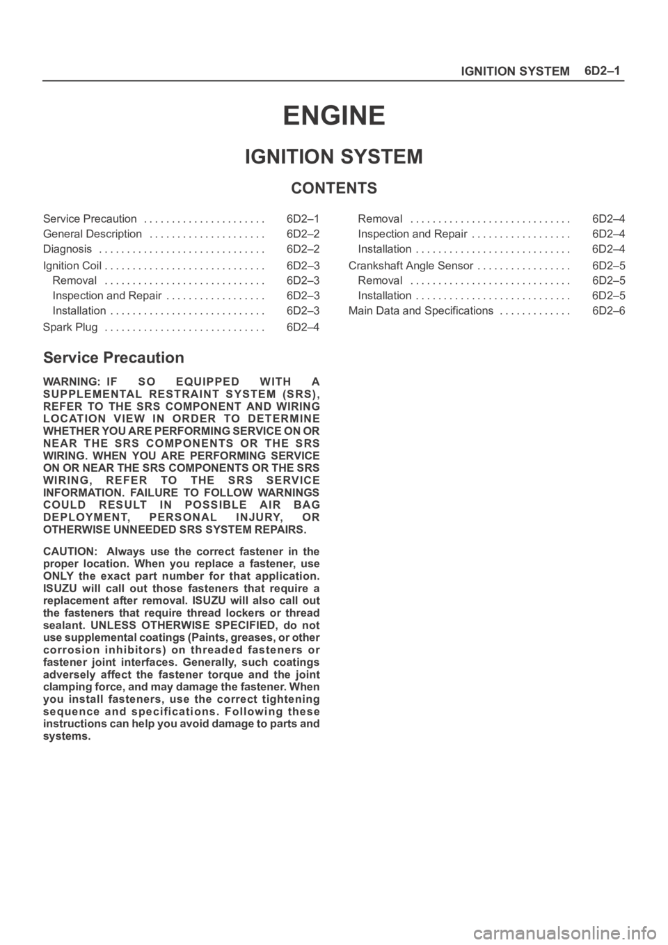
6D2–1
IGNITION SYSTEM
ENGINE
IGNITION SYSTEM
CONTENTS
Service Precaution 6D2–1. . . . . . . . . . . . . . . . . . . . . .
General Description 6D2–2. . . . . . . . . . . . . . . . . . . . .
Diagnosis 6D2–2. . . . . . . . . . . . . . . . . . . . . . . . . . . . . .
Ignition Coil 6D2–3. . . . . . . . . . . . . . . . . . . . . . . . . . . . .
Removal 6D2–3. . . . . . . . . . . . . . . . . . . . . . . . . . . . .
Inspection and Repair 6D2–3. . . . . . . . . . . . . . . . . .
Installation 6D2–3. . . . . . . . . . . . . . . . . . . . . . . . . . . .
Spark Plug 6D2–4. . . . . . . . . . . . . . . . . . . . . . . . . . . . . Removal 6D2–4. . . . . . . . . . . . . . . . . . . . . . . . . . . . .
Inspection and Repair 6D2–4. . . . . . . . . . . . . . . . . .
Installation 6D2–4. . . . . . . . . . . . . . . . . . . . . . . . . . . .
Crankshaft Angle Sensor 6D2–5. . . . . . . . . . . . . . . . .
Removal 6D2–5. . . . . . . . . . . . . . . . . . . . . . . . . . . . .
Installation 6D2–5. . . . . . . . . . . . . . . . . . . . . . . . . . . .
Main Data and Specifications 6D2–6. . . . . . . . . . . . .
Service Precaution
WARNING: IF SO EQUIPPED WITH A
SUPPLEMENTAL RESTRAINT SYSTEM (SRS),
REFER TO THE SRS COMPONENT AND WIRING
LOCATION VIEW IN ORDER TO DETERMINE
WHETHER YOU ARE PERFORMING SERVICE ON OR
NEAR THE SRS COMPONENTS OR THE SRS
WIRING. WHEN YOU ARE PERFORMING SERVICE
ON OR NEAR THE SRS COMPONENTS OR THE SRS
WIRING, REFER TO THE SRS SERVICE
INFORMATION. FAILURE TO FOLLOW WARNINGS
COULD RESULT IN POSSIBLE AIR BAG
DEPLOYMENT, PERSONAL INJURY, OR
OTHERWISE UNNEEDED SRS SYSTEM REPAIRS.
CAUTION: Always use the correct fastener in the
proper location. When you replace a fastener, use
ONLY the exact part number for that application.
ISUZU will call out those fasteners that require a
replacement after removal. ISUZU will also call out
the fasteners that require thread lockers or thread
sealant. UNLESS OTHERWISE SPECIFIED, do not
use supplemental coatings (Paints, greases, or other
corrosion inhibitors) on threaded fasteners or
fastener joint interfaces. Generally, such coatings
adversely affect the fastener torque and the joint
clamping force, and may damage the fastener. When
you install fasteners, use the correct tightening
sequence and specifications. Following these
instructions can help you avoid damage to parts and
systems.