weight OPEL GT-R 1973 Service Manual
[x] Cancel search | Manufacturer: OPEL, Model Year: 1973, Model line: GT-R, Model: OPEL GT-R 1973Pages: 625, PDF Size: 17.22 MB
Page 10 of 625
GENERAL INt=ORMATION OA-1
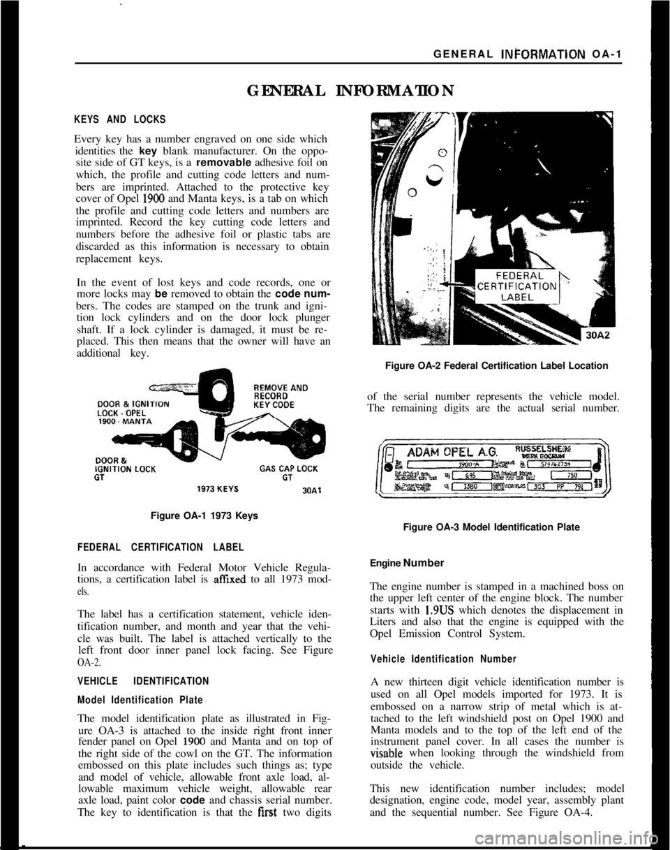
GENERAL INFORMATIONKEYS AND LOCKSEvery key has a number engraved on one side which
identities the key blank manufacturer. On the oppo-
site side of GT keys, is a removable adhesive foil on
which, the profile and cutting code letters and num-
bers are imprinted. Attached to the protective key
cover of Opel
1900 and Manta keys, is a tab on which
the profile and cutting code letters and numbers are
imprinted. Record the key cutting code letters and
numbers before the adhesive foil or plastic tabs are
discarded as this information is necessary to obtain
replacement keys.
In the event of lost keys and code records, one or
more locks may be removed to obtain the code num-
bers. The codes are stamped on the trunk and igni-
tion lock cylinders and on the door lock plunger
shaft. If a lock cylinder is damaged, it must be re-
placed. This then means that the owner will have an
additional key.REMOVE ANDDOOR &
IGNIKEY CODELOCK. OPELIGNITION
LOCKGAS CAP LOCKGTGT
Figure OA-1 1973 Keys
FEDERAL CERTIFICATION LABELIn accordance with Federal Motor Vehicle Regula-
tions, a certification label is
affIxed to all 1973 mod-
els.The label has a certification statement, vehicle iden-
tification number, and month and year that the vehi-
cle was built. The label is attached vertically to the
left front door inner panel lock facing. See Figure
OA-2.
VEHICLE IDENTIFICATION
Model Identification PlateThe model identification plate as illustrated in Fig-
ure OA-3 is attached to the inside right front inner
fender panel on Opel
1900 and Manta and on top of
the right side of the cowl on the GT. The information
embossed on this plate includes such things as; type
and model of vehicle, allowable front axle load, al-
lowable maximum vehicle weight, allowable rear
axle load, paint color code and chassis serial number.
The key to identification is that the first two digitsFigure OA-2 Federal Certification Label Location
of the serial number represents the vehicle model.
The remaining digits are the actual serial number.
Figure OA-3 Model Identification Plate
Engine Number
The engine number is stamped in a machined boss on
the upper left center of the engine block. The number
starts with 1.9US which denotes the displacement in
Liters and also that the engine is equipped with the
Opel Emission Control System.
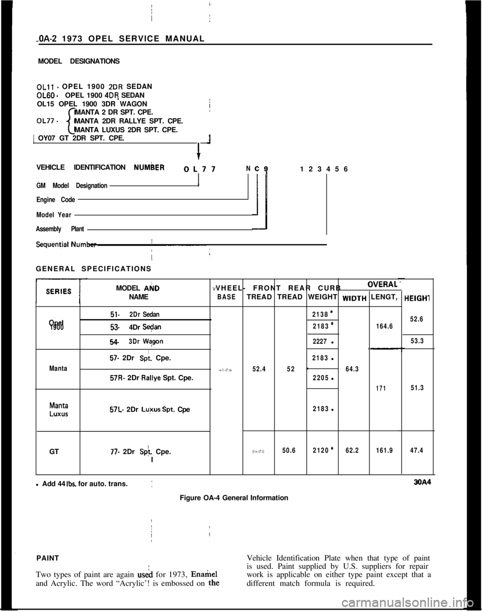
Vehicle Identification NumberA new thirteen digit vehicle identification number is
used on all Opel models imported for 1973. It is
embossed on a narrow strip of metal which is at-
tached to the left windshield post on Opel 1900 and
Manta models and to the top of the left end of the
instrument panel cover. In all cases the number isvisable when looking through the windshield from
outside the vehicle.
This new identification number includes; model
designation, engine code, model year, assembly plant
and the sequential number. See Figure OA-4.
Page 11 of 625
sOA- 1973 OPEL SERVICE MANUAL _
MODEL DESIGNATIONSOLll - OPEL 1900 2DR SEDANOL60
-OPEL 1900 4DR SEDAN
OL15 OPEL 1900 3DR WAGON
MANTA 2 DR SPT. CPE.
OL77 -
cMANTA 2DR RALLYE SPT. CPE.
MANTA LUXUS 2DR SPT. CPE.1 OY07 GT 2DR SPT. CPE.
+
1VEHICLE IDENTIFICATION NUMbER
OL77N
GM Model Designation
I
Engine Code
Model Year
Assembly Plant
c9123456
ilGENERAL SPECIFICATIONS
MODEL AI(ID
NAME I
Opel
1900
Manta
51.2DrSedan
53.4DrS+n
54.3DrWqgon
57. 2Dr Spi. Cpe.57R- 2Dr R&ye Spt. Cpe.
Manta
LUXUS57L. 2Dr Lu+sSpt. Cpe
GT
77. 2Dr Splf. Cpe.
IVVHEEL- FRONT REAR CURBOVERAL
BASETREAD TREAD WEIGHT WIDTH LENGT,
2138=
2183*164.6
2227l
2183l
95.752.452-64.3
2205l
171
2183l
49.450.62120*62.2161.9l Add 44
Ibs. for auto. trans.
Figure OA-4 General InformationHElGHl
52.6
53.3
51.3
47.4PAINTVehicle Identification Plate when that type of paint
Two types of paint are again useh for 1973, Enamelis used. Paint supplied by U.S. suppliers for repair
work is applicable on either type paint except that a
and Acrylic. The word “Acrylic’! is embossed on thedifferent match formula is required.
/
Page 67 of 625
1F. 46 1973 OPEL SERVICE MANUAL
’
/
Headlight High-Low Beam Control and Passing:
SignalI
When the headlights have been switched on, high
and low beam selection is made by raising the direc-
tional signal lever toward steering wheel. Each
ti&the lever is raised, beam position, will change.
When the headlights are not on, a flashing headlight
signal may be given by raising and lotiering the di-
rectional signal lever. With the headlights on and
inlow beam position, raising and lowering the direc-
tional signal lever will also cause the headlights to
flash.
Fog Light SwitchAll Rallye models are equipped with two white f?g
lights mounted below the front bumper.
The fog light toggle switch is located on the
insty-ment cluster to the left of the temperature and
fuelgauge cluster.
/
The fog lights can be turned off at any time by the
toggle switch, but can only be tyrned on when: :
1. The ignition switch on or the
?gine running.!
2. The fog light toggle switch lower half is pushed
in.3. The parking lights and/or low beam headlights
are
OKThe fog lights are automatically turned off if the
ignition switch is on and the headlights are switched
to high beam position.
Courtesy LightThe courtesy light illuminates the interior of the Car
when any door is opened. The courtesy light can also
be turned on with all doors closed by tilting the l&s.
GT Headlamp MechanismThe concealed headlamps are moved mechanically.
Pushing actuating lever on left side of console opens
headlamps and pulling lever closes headlamps. Two
(2) meshing gear segments convert the movement, of
the lever to a rotation of 180 degrees. The pivots of
the headlamps lie below the centerline so that with
headlamps in closed position, the headlamp housing
is flush with front sheet metal. Refer to Group 110,
Section “F”, for service procedures on the GT head-
lamp mechanism.
A white indicator lamp in the instrument panel lights
if the headlamps are not completely opened lorclosed The switches of the headlamp electrical sys-
tem are located behind the left headlamp operating,
mechanism.
MAINTENANCE AND ADJUSTMENTSHEADLAMP AIMING
The headlamps must be properly aimed in order to
obtain maximum road illumination and safety that
has been built into the headlighting equipment. With
the Guide T-3 type sealed beam units, proper aiming
is even more important because the increased range
and power of this lamp make even slight variations
from recommended aiming hazardous to approach-
ing motorists. The headlamps must be checked for
proper aim whenever a sealed beam unit is replaced
and after an adjustment or repairs of the front end
sheet metal assembly.
Regardless of method used for checking headlamp
aim, car must be at normal weight, that is, with gas,
oil, water, and spare tire. Tires must be uniformly
inflated to specified pressure. If car will regularly
carry an unusual load in rear compartment, or a
trailer, these loads should be on car when headlamps
are checked. Some States have special requirements
for headlamp aiming adjustment, and these require-
ments should be known and observed.
Horizontal and vertical aiming of each seal beam
unit is provided by two adjusting screws which move
the mounting ring in the body against the tension of
the coil spring. There is no adjustment for focus,
since the sealed beam unit is set for proper focus
during manufacturing assembly.
MAJOR REPAIRHEADLIGHT SWITCH
- OPEL 1900. MANTA
Removal1. Remove instrument cluster cover panel. See Sec-
tion H.
2. Compress retaining springs and pull switch out.
See Figure 1 F-
1.3. Pull multiple socket off switch.
Installation
1: Plug multiple socket in switch and push switch in
panel until clips lock in place.
2. Replace instrument cover and secure with two (2)
screws.
Page 164 of 625

3116” SPACERSAFET‘;. CHAIN PLATE
(Dl -l/Z x 3INSTALLATION INSTRUCTIONS
1969
- 73 OPEL GT TRAILER HITCH LESS BALL
GROUP 7.068
STEP 1.REMOVE ONE RIGHT HAND AND ONE LEFT HAND
TAIL LAMP ASSEMBLY,
STEP 2.PLACE TIE BAR (C) UNDER THE REAR BODY
PANEL BY PULLING DOWN ON THE EXHAUST PIPES AND
SLIDING THE TIE BAR OVER THE PIPES AND INTO
POSITION. PLACE DRAW BAR (Al UNDER TIE BAR ICI
AND FASTEN WITH A
112 x 2” HEX BOLT WITH LOCK
WASHER AND NUT UNDER DRAW BAR (A). PLACE TIE
BAR (8) UNDER DRAW BAR IAl AND SAFETY CHAIN PLATE(DI UNDER TIE BAR
(B) AND FASTEN WITH A 112 ‘x 2-114”HEX BOLT WITH FLAT WASHER, LOCK WASHER AND NUT
BELOW SAFETY CHAIN PLATE IDI.
STEP 3. HOLD HITCH IN POSITION WITH TIE BAR (Cl
UNDE~R THE REAR BODY PANEL AND TIE BAR (RI
BETWEEN THE BUMPER GUARDS. USING THE HOLES IN
THE ENDS OF TIE BAR (Cl AS A GUIDE, LOCATE, MARK
AND DRILL TWO
112” HOLES IN THE VERTICAL PORTION
OF THE REAR BODY PANEL. PLACE THE 3/16” SPACERS
ON THE
112 x l-l/2 HEX BOLTS AND BY REACHING
THROUGH THE TAIL LAMP OPENINGS, INSERT THE BOLTS
THROUGH THE BODY PANEL AND TIE BAR (Cl AND
FASTEN WITH LOCK WASHER AND NUT.
STEP 4. ALIGN TIE BAR (8) BETWEEN THE
BUMP,ER GUARDS
AND LOCATE, MARK AND DRILL A 112~ HOLE THROUGH
BOTH SIDES OF THE BUMPER GUARD USING THE HOLES
IN TIE BAR IBI AS A GUIDE. MAINTAIN
112 lNCH.MlNlMUM
CLEARANCE BETWEEN TOP OF DRAW BAR.(A) AND
BOTTOM OF BACK-UP LIGHT. FASTEN TIE BAR
(Bl ,TO’THE BUMPER GUARDS WITH 112 x 3” BOLTS WITH TWO.112”
SPACERS AND ONE 318” SPACER INSIDE EACH BUMPER
GUARD. REPLACE TAIL LAMP ASSEMBLES.
TIGHTEN ALL
112” NUTS.TO A MAXIMUP,.TOROUE OF
60 FOOT LBS.
INSTALL BALL US1NG.A MAXIMUM.TOR~DUE OF
150 FOOT LBS.
MAXIMUM GROSS WEIGHT 1000 LBS.
MAXIMUM TONGUE WEIGHT 100 LBS.
MOST STATES PROHIBIT OBSTRUCTION OF LICENSE.
PLATES. BALL SHOULD BE REMOVED WHEN NOT IN
USE IF IT OBSTRUCTS A CLEAR VIEW.2H.8
Figure 2H-8 GT Trailer Hitch Installation
Page 165 of 625

FLVTRlJNK PLAT
DRAW BAR16x1-1/2 -DRAW‘ BAR EXTENSION-%GSAFETY CHAIN PLATE6INSTALLATION INSTRUCTIONS
1971
- 72 - 73 OPEL 1900 SERIES S/W
GROUP NO. 7.068
REMOVE LICENSE PLATE
STEP 1. ASSEMBLE HITCH AS ILLUSTRATED. HOLD
HITCH IS POSITION WITH FLOOR PLATE RESTING
AGAINST THE CROSS FRAME IN FRONT OF GAS TANK.
CENTER DRAW BAR SUPPORT ON THE REAR BODY
PANEL, RAISE UNTIL LEVEL.
STEP 2.MARK AND DRILL TWO
7116” HOLES IN REAR
BODY PANEL AND ATTACH AS SHOWN.
STEP 3.DRILL TWO
112” HOLES IN CROSS FRAME IN
FRONT OF THE GAS TANK AND CONTINUE DRILLING UP
THROUGH THE INNER FLOOR. NOTE: HOLD DRILL
VERTICAL WHILE DRILLING THROUGH THE INNER FLOOR.
ENLARGE BOTTOM HOLE SLIGHTLY TO ACCEPT SPACER.
STEP 4. ATTACH TRUNK PLATE AS ILLUSTRATED. PLACE
THE FLOOR PLATES ON THE 2
l/2” CARRIAGE BOLTS
AND INSERTS THROUGH THE OPENINGS
iN THE BACK OF
THE TRUNK WELL.INSERT SPACERS AS SHOWN AND
COMPLETE INSTALLATION.
REPLACE LICENSE PLATE.
TIGHTEN ALL
112” NUTS TO A MAXIMUM TORQUE OF
60 FOOT LBS. AND 7/16” NUTS TO A MAXIMUM OF
45 FOOT LBS.
INSTALL BALL USING A MAXIMUM TORQUE OF 150
FOOT LBS.
MAXIMUM GROSS WEIGHT 100 LBS
MAXIMUM TONGUE WEIGHT 100 LBS.
MOST STATES PROHIBIT OBSTRUCTION OF LICENSE
PLATES, BALL SHOULD BE REMOVED WHEN NOT IN
USE IF IT OBSTRUCTS A CLEAR VIEW.
ZH-9Figure
ZH-9 Opel 1900 Wagon Trailer Hitch Installation
Page 166 of 625

AFETY CHAINPLATEINSTALLATION INSTRUCTIONS
1971-72-73 OPEL 50 SER.. LESS S/WAGON CAR TRAILER HITCH
GROUP NO. 7.068
STEP 1.REMOVE LICENSE PLATE, ASSEMBLE V-BAR AND
SAFETY CHAIN PLATE TO DRAW BAR AS ILLUSTRATED.
HOLD HITCH IN POSITION WITH THE DRAW EAR LEVEL
AND THE V-BAR RESTING ON THE REAR BODY PANEL.
MARK AND DRILL TWO l/2” HOLES THROUGH THE BODY
AND ATTACH THE V-BAR AS ILLUSTRATED.
STEP ‘2. ALIGN THE ORAW BAR IN THE CENTER OF THE
TRUCK FLOOR AND DRILL A
l/2” HOLE THROUGH THE
FLOOR USING THE HOLE IN THE DRAW BAR AS A GUIDE.
ATTACH THE FLOOR PLATE AND FLOOR STRAP AS
ILLUSTRATED. DRILL THE TWO REMAINING HOLES IN
THE FLOOR AND COMPLETE INSTALLATION AS ILLUSTRATED
REPLACE LICENSE PLATE.
TIGHTEN ALL
112” NUTS TO A TORQUE OF 60 FOOT LBS.II\STALL BALL USING A TORQUE OF 150 FOOT LBS.
MAXIMUM GROSS WEIGHT 1000 LBS.
MAXIMUM TONGUE WEIGHT 100 LBS.
MOST STATES PROHIBIT OBSTRUCTION OF LICENSE PLATES.
BALL SHOULD BE REMOVED WHEN NOT IN USE IF IT
OBSTRUCTS A CLEAR VIEW.
ZH-10Figure ZH-10 Opel 1900
- Manta - Less Wagon -Trailer Hitch lnsfallafion
Page 219 of 625
3F. 521973 OPEL SERVICE MANUAL
3. Install rubber grommet, retainer and self-locking
nut at top of shock absorber. Torque to 10 lb. ft.
Always use new self-locking nuts.
REAR SPRING REMOVAL AND INSTALLATION
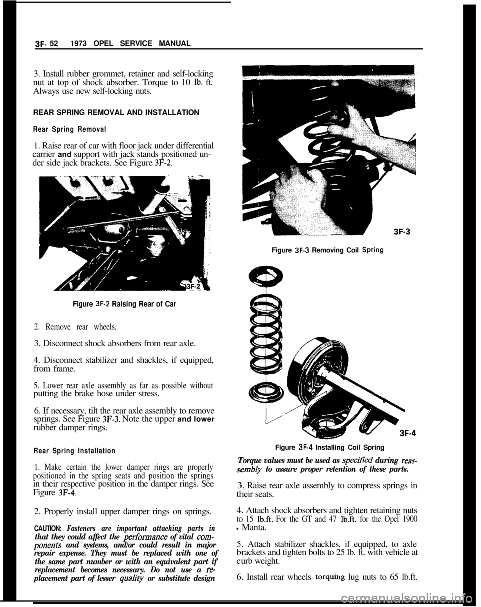
Rear Spring Removal1. Raise rear of car with floor jack under differential
carrier and support with jack stands positioned un-
der side jack brackets. See Figure
3F-2.Figure 3F-3 Removing Coil
SpringFigure 3F-2 Raising Rear of Car
2. Remove rear wheels.3. Disconnect shock absorbers from rear axle.
4. Disconnect stabilizer and shackles, if equipped,
from frame.
5. Lower rear axle assembly as far as possible withoutputting the brake hose under stress.
6. If necessary, tilt the rear axle assembly to remove
springs. See Figure
3F-3. Note the upper and lower
rubber damper rings.
Rear Spring Installation
1. Make certain the lower damper rings are properly
positioned in the spring seats and position the springsin their respective position in the damper rings. See
Figure
3F-4.2. Properly install upper damper rings on springs.
CAUTION: Fasteners are important attaching parts in
that they could affect the performance of vital corn-
ponents and systems, and/or could result in major
repair expense. They must be replaced with one of
the same part number or with an equivalent part if
replacement becomes necessary. Do not use a
re-
placement part of lesser
qua/ity or substitute designFigure 3F-4 Installing Coil Spring
Torque values must be used as specitied during reas-
sembly to assure proper retention of these parts.3. Raise rear axle assembly to compress springs in
their seats.
4. Attach shock absorbers and tighten retaining nuts
to 15 Ib.ft. For the GT and 47 lb.ft. for the Opel 1900
- Manta.
5. Attach stabilizer shackles, if equipped, to axle
brackets and tighten bolts to 25 lb. ft. with vehicle at
curb weight.
6. Install rear wheels torquing lug nuts to 65 lb.ft.
Page 229 of 625

3G- 621973 OPEL SERVICE MANUAL
1. Clean rims thoroughly, using No. 3 coarse steel
wool to remove all oxidized rubber, soap solution,
etc. Remove rust with wire brush.2. Inspect butt weld and other areas of rim contactedby tire beads to make certain there is no groove or
high spot. Remove any groove or high spot by tiling
smooth.
3. Inspect valve stem and replace it if damaged.
Make certain that valve stem is properly installed to
provide an air tight joint.
4. Before mounting a tubeless tire on a wheel, mois-
ten a cloth with mounting compound or soap solu-
tion and wipe rim-seal ridges of both beads to remove
all foreign substances.
5. Moisten base of both beads with mounting com-
pound or soap solution to help beads snap into place
when tire is inflated. Start tire over rim flange at
point opposite valve stem.
6. Inflate tire until both beads are firmly seated
against rim flanges and temporarily over inflate.
Leak test wheel and tire assembly and if satisfactory,
reduce to recommended pressure.
SPECIFICATIONSWHEEL AND TIRE BALANCE
Wheel and tire balance is the equal distribution of the
weight of the wheel and tire assembly around the axis
of rotation. Wheel unbalance is the principal cause of
tramp and general car shake and roughness and con-
tributes somewhat to steering troubles.
The original balance of the tire and wheel assembly
may change as the tire wears. Severe acceleration,
severe brake applications, fast cornering and side slip
wear the tires out in spots and often upset the origi-
nal balance condition and make it desirable to rebal-
ance the tire and wheel as an assembly. Tire and
wheel assemblies should be rebalanced after punc-
tures are repaired.
Because of the speed at which cars are driven, it is
necessary to test the wheel and tire assembly for
dynamic balance. Dynamic balancing of a wheel and
tire assembly must be done on a machine designed to
indicate out-of-balance conditions while the wheel is
rotating on the car. Since procedures differ with dif-
ferent machines, the instructions of the equipment
manufacturer must be carefully followed.
General SpecificationsWheels
Opel 1900
- Manta and GT ,._......,,,._.................,...,,..............................~,,,.................... 5.J x 13
Tires
1900 - Manta __.......,,___.,...,,..,.....,,....,,...........,...,,.,,...,.........,,..................,....................... 165-13
GT . . . . . . . ..__........_..............,...,,........,,,...,,..........,....,..,,...,,........,..................,,,.....................165-13
Tire Size and Pressures (Pounds Per Square Inch
Cold)
ModelTire Size51.53.54.57
165-1357R.57L165-13
77
165-13Recommended(Standard
PressureInflation)
FrontRear24
PSI32PSI23
PSI26PSI
19PSI23
PSI
NOTE:
1.Tire inflation pressures may increase as much as 6 pounds per square inch
when hot.
2.For continuous high-speed operation (over 75 MPH), increase tire inflation
pressures 4 pounds per square inch over the recommended pressures up to a
maximum of 30 pounds per square inch cool for 4 ply rating tires. When the
4 psi pressure adjustment for sustained high speed with maximum vehicle load
Page 238 of 625
REAR AXLE
CONTENTS
SubjectPage No.
DESCRIPTION AND OPERATION:
Rear Axle Description. . . . . . . . . . . . . . . . . . . . . . . . . . . . . . . . . . . . . . . . . . . . . . . . . . . . . .4B- 7
DIAGNOSIS:
RearAxleTroubleDiagnosis. . . . . . . . . . . . . . . . . . . . . . . . . . . . . . . . . . . . . . . . . .4B- 8
MAINTENANCE AND ADJUSTMENTS: (Not Applicale)
MAJOR REPAIR:
Removal and Installation of Rear Axle Assembly
Removal and Installation of Axle Shaft Assembly
Disassembly and Assembly of Differential
.* . . . . . . . . . . . .SPECIFICATIONS:
DifferentialSpecifications
. . . . . . . . . . . . . . . . . . . . . . . . . . . . . . . . . . . . . . . . . . . . . .4B- 94B-10
48-l 1
4B-22
DESCRIPTION AND OPERATION
REAR AXLE DESCRIPTIONThe Opel rear axle is a semi-floating type that carries
car weight through the axle shafts by way of ball
bearings which are located on the outer ends of each
axle shaft. The rear axle assembly is attached to the
under body by way of the shock absorbers, track rod,
central joint support, and lower control arms. A sta-
bilizer rod is used on all Wagons, as well as Fast
Backs and Sedans. The GT is not equipped with a
stabilizer rod. The rear springs have a progressive
spring rate which is attained by a gradual reduction
of coil thickness. The springs are arranged between
the spring seats welded onto the rear axle tubes and
the under body side members. The upper and lower
ends are seated in profiled rubber dampening rings.
The differential housing is a malleable iron casting
with tubular axle housings pressed into the sides to
form a complete assembly. An oil feed passage to the
pinion bearings and an oil return hole are provided
to allow lubricant to circulate. A removable steel
cover is bolted on the rear of the differential housing
to permit service of the differential without removing
the rear axle assembly from the vehicle. A breather
fitting is located on top of the right axle tube.Within the differential carrier, the differential case is
supported by two tapered roller side bearings. These
side bearings are preloaded by shims located between
the bearing inner races and differential case. During
installation, varying the shim thickness from side to
side also determines the ring gear to pinion backlash.
The differential case houses two side gears meshed
with two pinions. The pinions and side gears are
backed by thrust washers. The pinion gears are held
in place by a pinion shaft which is anchored in the
differential case by a lock pin.
The inner end of the axle shafts engage and extend
through the splines of the side gears with a floating
tit.
The axle shafts have an enlarged diameter from mid-
shaft to the flange end.
A ball bearing and oil seal are used on all models, and
are pressed onto the outer end of the axle shaft as an
assembly.The drive pinion is mounted in two roller bearings in
the rear axle housing. Pinion setting is established by
shims located between the differential carrier and therear’pinion bearing outer race.
Page 241 of 625
4B- 101973 OPEL SERVICE MANUAL
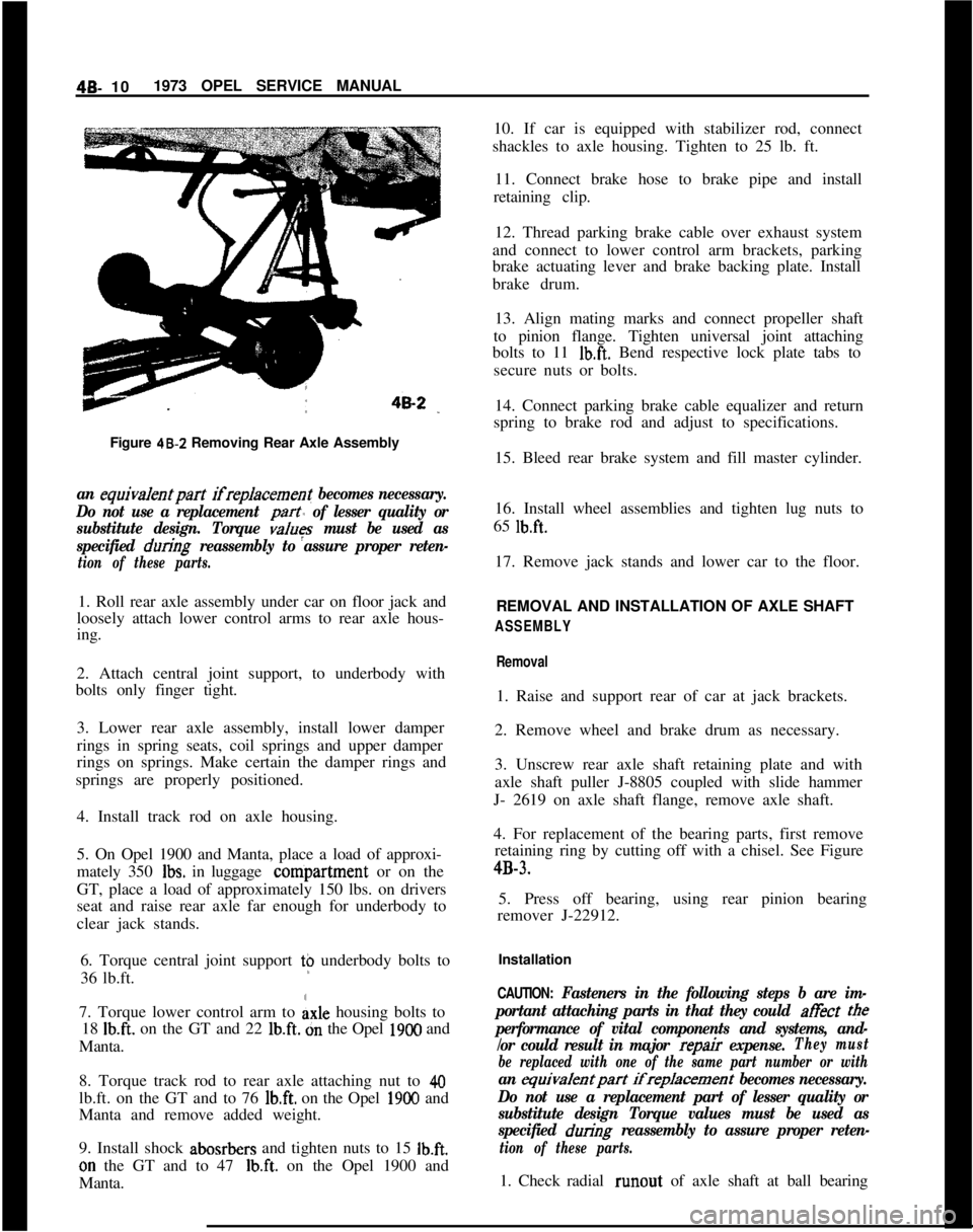
Figure 48-Z Removing Rear Axle Assemblyan equiva/entpart ifreplacement becomes necessary.
Do not use a replacement
part of lesser quality or
substitute design. Torque
values must be used as
specified
during reassembly to assure proper reten-
tion of these parts.1. Roll rear axle assembly under car on floor jack and
loosely attach lower control arms to rear axle hous-
ing.
2. Attach central joint support, to underbody with
bolts only finger tight.
3. Lower rear axle assembly, install lower damper
rings in spring seats, coil springs and upper damper
rings on springs. Make certain the damper rings and
springs are properly positioned.
4. Install track rod on axle housing.
5. On Opel 1900 and Manta, place a load of approxi-
mately 350
Ibs. in luggage conipartment or on the
GT, place a load of approximately 150 lbs. on drivers
seat and raise rear axle far enough for underbody to
clear jack stands.
6. Torque central joint support t$ underbody bolts to
36 lb.ft.
7. Torque lower control arm to
Axle housing bolts to
18
Ib.ft. on the GT and 22 lb.ft. dn the Opel 1900 and
Manta.
8. Torque track rod to rear axle attaching nut to
40lb.ft. on the GT and to 76
lb.ft. on the Opel 1900 and
Manta and remove added weight.
9. Install shock abosrbers and tighten nuts to 15
Ib.ft.on the GT and to 47
Ib.ft. on the Opel 1900 and
Manta.10. If car is equipped with stabilizer rod, connect
shackles to axle housing. Tighten to 25 lb. ft.
11. Connect brake hose to brake pipe and install
retaining clip.
12. Thread parking brake cable over exhaust system
and connect to lower control arm brackets, parking
brake actuating lever and brake backing plate. Install
brake drum.
13. Align mating marks and connect propeller shaft
to pinion flange. Tighten universal joint attaching
bolts to 11
Ib.ft. Bend respective lock plate tabs to
secure nuts or bolts.
14. Connect parking brake cable equalizer and return
spring to brake rod and adjust to specifications.
15. Bleed rear brake system and fill master cylinder.
16. Install wheel assemblies and tighten lug nuts to
65
lb.ft.17. Remove jack stands and lower car to the floor.
REMOVAL AND INSTALLATION OF AXLE SHAFT
ASSEMBLY
Removal1. Raise and support rear of car at jack brackets.
2. Remove wheel and brake drum as necessary.
3. Unscrew rear axle shaft retaining plate and with
axle shaft puller J-8805 coupled with slide hammer
J- 2619 on axle shaft flange, remove axle shaft.
4. For replacement of the bearing parts, first remove
retaining ring by cutting off with a chisel. See Figure4B-3.
5. Press off bearing, using rear pinion bearing
remover J-22912.
Installation
CAUTION: Fasteners in the following steps b are im-
portant attaching parts in that they could at&t
tee
performance of vital components and systems, and-
/or could result in major
repair expense.They must
be replaced with one of the same part number or with
an equivalentpart ifreplacement becomes necessary.
Do not use a replacement part of lesser quality or
substitute design Torque values must be used as
specified
during reassembly to assure proper reten-
tion of these parts.1. Check radial runout of axle shaft at ball bearing