checking oil OPEL GT-R 1973 Owner's Manual
[x] Cancel search | Manufacturer: OPEL, Model Year: 1973, Model line: GT-R, Model: OPEL GT-R 1973Pages: 625, PDF Size: 17.22 MB
Page 529 of 625

98-20 1973 OPEL SERVICE MANUAL
If we were to put a thermometer in the cold drain
water, we would see the temperature gradually creep
upwards. That is to be expected because heat is flow-
ing into the cold water making it warmer. Before
long the water would be as warm as the stored foods.
Then the water could no longer attract heat because
heat will not flow from one warm object to another
equally warm object. Since we no longer can draw
heat out of the foods we no longer are cooling them.
Now, let’s see what happens when we put ice instead
of cold water into the ice-box. This time, we’ll set the
thermometer on top of the ice (Fig. 9B-5). When wefirst look at the thermometer, it reads 32 degrees. A
couple of hours later, we open the ice compartment
door. The ice block is smaller because some of the ice
has already melted away
- but the thermometer still
reads 32 degrees. Again, still later, even more of the
ice has melted, yet the termometer continues to read
32 degrees. So long as any ice remains, no matter
how much of it has melted away, the temperature of
the ice stays right at 32 degrees.
All this time the ice has been soaking up heat, yet it
never gets any warmer no matter how much heat it
draws from the stored food. On the other hand, the
cold drain water got progressively warmer as it
soaked up heat. Why is it the addition of heat will
make water warmer yet won’t raise the temperature
of ice above the 32 degrees mark? If we till one
drinking glass with ice and another with cold water,
and put both glasses in the same room where they
could absorb equal amounts of heat from the room
air, we will find it takes much, much longer for the
ice to melt and reach room temperature than it did
for the water in the other glass to reach the same
temperature. Obviously, most of the heat was being
used to melt the ice. But it was the heat that appar-
ently disappeared or went into hiding because if
couldn’t be located with a thermometer. To best de-
scribe this disappearing heat, scientists turned to
Latin for the right word. They chose the word “la-
tent” which means hidden.
Latent Heat
So latent heat is nothing more nor less than hidden
heat which can’t be found with a thermometer.
What happens to the latent heat? Where does it
disappear to? At first it was thought it was in the
water that melted from the ice. But that wasn’t ex-
actly the right answer because, upon checking water
temperature as it melts from ice, it will be found that
it is only a shade warmer than the ice itself. It is not
nearly warm enough to account for all the heat the
ice had absorbed. The only possible answer is that
the latent heat had been used up to change the ice
from a solid into a liquid.
Many substances can be either a solid, or a liquid, ora gas. It just depends on the temperature whether
water for example was a liquid, or a solid (ice), or gas
(steam) (Fig.
9B-6).Figure 99-6 Temperature Determines State of Water
If we put some water in a tea-kettle, set it over a tire
and watch the thermometer as the water gets hotter
and hotter, the mercury will keep rising until the
water starts to boil. Then the mercury seems to stick
at the 212 degrees mark. If we put more wood on the
fire, despite all the increased heat, the mercury will
not budge above the 212 degree mark (Fig.
9B-7).Figure 98.7 Boiling Water Never Exceeds 2 12
DegreesEven though many housewives won’t believe it, no
matter how large or hot you make the flame, you
can’t make water hotter than 2 12 degrees. As a liquid
changes into a gas, it absorbs abnormally great
amounts of heat without getting any hotter. Here is
another instance where heat disappears.
Now we have two different kinds of latent heat,
which are quite alike. To keep their identities sepa-
rate, the first one is called latent heat of fusion. Since
fusion means the same as melting, it is a good de-
scriptive name. The other kind is called latent heat
of vaporization because‘ that means the same as
evaporation.
It may seem as though we have drifted into a story
Page 583 of 625

98.74 1973 OPEL SERVICE MANUAL
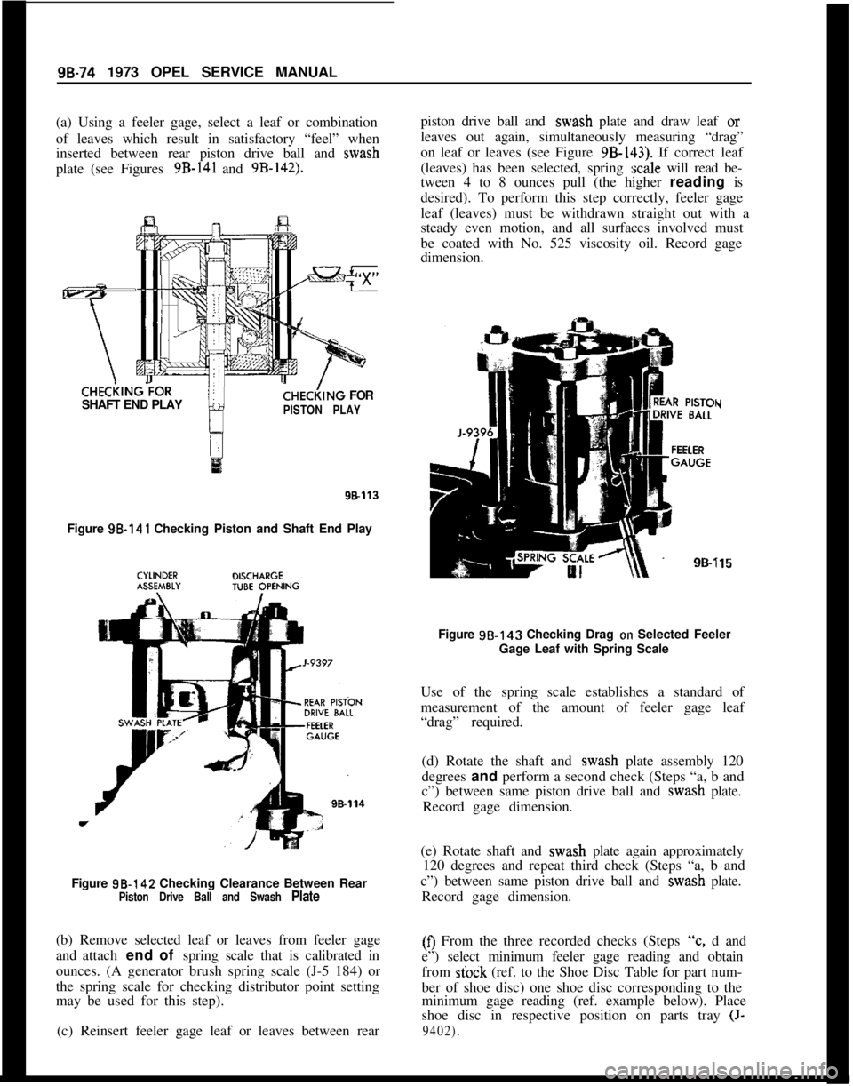
(a) Using a feeler gage, select a leaf or combination
of leaves which result in satisfactory “feel” when
inserted between rear piston drive ball and wash
plate (see Figures 9B-141 and 9B-142).CHECi(lNG?OR
SHAFT END PLAY
CHE&NG FOR
PISTON PLAY
98113Figure 98-141 Checking Piston and Shaft End Play
Figure 98-142 Checking Clearance Between Rear
Piston Drive Ball and Swash Plate(b) Remove selected leaf or leaves from feeler gage
and attach end of spring scale that is calibrated in
ounces. (A generator brush spring scale (J-5 184) or
the spring scale for checking distributor point setting
may be used for this step).
(c) Reinsert feeler gage leaf or leaves between rearpiston drive ball and wash plate and draw leaf or
leaves out again, simultaneously measuring “drag”
on leaf or leaves (see Figure
9B-143). If correct leaf
(leaves) has been selected, spring
:scale will read be-
tween 4 to 8 ounces pull (the higher reading is
desired). To perform this step correctly, feeler gage
leaf (leaves) must be withdrawn straight out with a
steady even motion, and all surfaces involved must
be coated with No. 525 viscosity oil. Record gage
dimension.
Y
i15Figure 98.143 Checking Drag
on Selected Feeler
Gage Leaf with Spring Scale
Use of the spring scale establishes a standard of
measurement of the amount of feeler gage leaf
“drag” required.
(d) Rotate the shaft and wash plate assembly 120
degrees and perform a second check (Steps “a, b and
c”) between same piston drive ball and wash plate.
Record gage dimension.
(e) Rotate shaft and wash plate again approximately
120 degrees and repeat third check (Steps “a, b and
c”) between same piston drive ball and wash plate.
Record gage dimension.(0 From the three recorded checks (Steps
“c, d and
e”) select minimum feeler gage reading and obtain
from
stock (ref. to the Shoe Disc Table for part num-
ber of shoe disc) one shoe disc corresponding to the
minimum gage reading (ref. example below). Place
shoe disc in respective position on parts tray
(J-
9402).
Page 584 of 625

REFRIGERANT COMPONENTS ALL MODELS9B- 75Shoe Disc TableSERVICEID. NO.
PART NO. STAMPED
6557000
6556175
6556180
65561856556190
65561956556200
65562056556210
65562156556220
EXAMPLESHOE
DISC
0
(“ZSXO”Shoe
Disc)
17
l/218%
1919
l/2202&2
2121
l/2
22
Piston’
1st2nd3rdNo.
CheckCheckCheck
1,019,020,019(Select
No.19 -ShoeDisc)
2,020,020,019(Select
No.19-ShoeDisc)
3
.021,020.021(Select
No.20ShoeDisc)
(g) Repeat Steps “c, d, e and f’ for other two pistons
and obtain two more selected shoe discs for other
two pistons. In the rebuilt cylinder assembly, each
piston will have one selected shoe disc and one
“zero” shoe disc.
12. Gage shaft end play as follows:
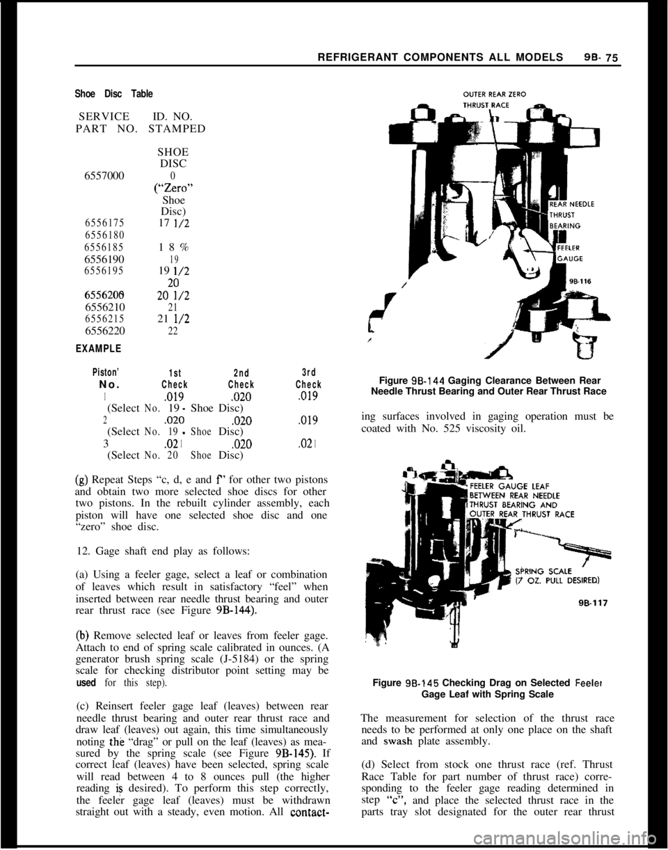
(a) Using a feeler gage, select a leaf or combination
of leaves which result in satisfactory “feel” when
inserted between rear needle thrust bearing and outer
rear thrust race (see Figure
9B-144).
(b) Remove selected leaf or leaves from feeler gage.
Attach to end of spring scale calibrated in ounces. (A
generator brush spring scale (J-5184) or the spring
scale for checking distributor point setting may be
used for this step).(c) Reinsert feeler gage leaf (leaves) between rear
needle thrust bearing and outer rear thrust race and
draw leaf (leaves) out again, this time simultaneously
noting the “drag” or pull on the leaf (leaves) as mea-
sured by the spring scale (see Figure
9B-145). If
correct leaf (leaves) have been selected, spring scale
will read between 4 to 8 ounces pull (the higher
reading is desired). To perform this step correctly,
the feeler gage leaf (leaves) must be withdrawn
straight out with a steady, even motion. All contact-Figure 98.144 Gaging Clearance Between Rear
Needle Thrust Bearing and Outer Rear Thrust Race
ing surfaces involved in gaging operation must be
coated with No. 525 viscosity oil.
Figure 98.145 Checking Drag on Selected
FeeletGage Leaf with Spring Scale
The measurement for selection of the thrust race
needs to be performed at only one place on the shaft
and wash plate assembly.
(d) Select from stock one thrust race (ref. Thrust
Race Table for part number of thrust race) corre-
sponding to the feeler gage reading determined in
step
“C”,and place the selected thrust race in the
parts tray slot designated for the outer rear thrust
Page 622 of 625

Subject
Page NumbelSubjectPage Number4.Speed Manual I..
Clutch
Detent Cable Adjustment
:Differential
Directional Signal Switch
Repair Opel 1900 & Manta
Repair GT
:Disassembly of
4.Speed Manual Transmission
DistributorFunction of Valves and Hydraulic Control Units
Opel
3.Speed Automatic.................
74-21
Fuse Chart..............................lG-56
Fusible Link.............................
lA-8Specifications.
Point Replacement..
..,78-127A-
17c-9148-73E-393E-4878.23
1C-26
1 c-20
GEGas Tank See Fuel Tank
General Specifications
Engine...............................6A-28
Opel 3.Speed Automatic
.................7C-134
Transmission, Manual.,
..................78-33
Clutch...............................7A-7
Body................................ZA-4
Governor Drive Gear
Opel
3.Speed Automatic.................7C-103
Grille
Opel 1900 & Manta.....................8A-7
GT..................................8A-6 Electrically Heated Rear Window
Engine
General Description
Cooling System
Lubrication System
Trouble Diagnosis
Exhaust Manifold
Exhaust System
Removal and Installation
External Oil Leaks,
Opel 3 Speed Automatic
FFast Idle Adjustment
..................
Filter-Engine Oil
......................
Fluid Checking Procedure Transmission
Opel 3Speed Automatic.............
Frame-Opel 1900 & Manta.............
Frame
GT-Opel......................
SWVOOpel Xipeed Automatic...........
Front Suspension
Opel1900&Manta.................
GT..............................
Front Wheel Alignment................
Front Wheel Bearing Adjustment
All Series.........................
Fuel Gauge
Trouble Diagnosis
Opell$OO&Manta...............
GT............................
Fuel Pump Operation..................
Fuel System
Fuel Tank (Opel 1900 & Manta)
.......
Fuel Lines (Opel 1900 & Manta)
.......
Fuel Tank
(GT)....................
Fuel Gauge Tank Unit
(GT)...........
Fuel Lines
(GT)....................
Fuel Tank Removal and Installation....
Cleaning Tank.....................
lH-576A-268-326A-46A-66A-126D-427C-816E-51
oc-77C~Bl2B-826-77c-1003A-23A-23C-223A-4
HHazard Warning Flasher
....................lG-55
Headlamp Aiming
.........................1 F-46
Headlamp Switch
Opel 190.0 & Manta
.....................1 F-46
Headlamp Mechanism GT
..................8A-2
Heater System Opel 1900 &Manta
Trouble Diagnosis
......................9A-11
Description and Operation
................9A-10
Adjustments and Minor Service............9A-12
Removal and Installation
.................9A-12
Specifications..........................$A-16
Heater System GT
Trouble Diagnosis
......................9A-4
Description and Operation
................9A-2
Adjustments and Minor Service
............9A-4
Removal and Installation.................9A-5
Specifications..........................$A-9Horn
Operation.............................lG-54
Hydraulic Operation
Opel
3.Speed Automatic.................7C-64
IIdentification Number Vehicle...............
OA-1ldle.Adjustment
..........................6E-51
Inflation Pressures, Tires.
...................36-62
Ignition Coil
Specifications.
.........................
lC-26Identification, Engine
......................
OA-1Ignition System
Timing...............................
lC-20Instrument Panel Parts Removal