checking oil OPEL GT-R 1973 User Guide
[x] Cancel search | Manufacturer: OPEL, Model Year: 1973, Model line: GT-R, Model: OPEL GT-R 1973Pages: 625, PDF Size: 17.22 MB
Page 312 of 625
ENGINE MECHANICAL AND MOUNTS6A- 21
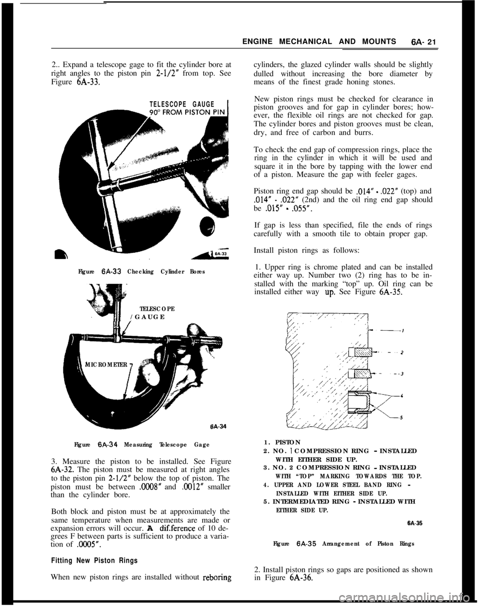
2.. Expand a telescope gage to fit the cylinder bore at
right angles to the piston pin 2-l/2” from top. See
Figure 6A-33.cylinders, the glazed cylinder walls should be slightly
dulled without increasing the bore diameter by
means of the finest grade honing stones.
TELESCOPE GAUGE1
Figure 6A-33 Checking Cylinder Bores
TELESCOPE/GAUGE
MICROMETER
Figure
6A-34 Measuring Telescope Gage3. Measure the piston to be installed. See Figure6A-32. The piston must be measured at right angles
to the piston pin
2-l/2” below the top of piston. The
piston must be between
.C008” and .0012” smaller
than the cylinder bore.
Both block and piston must be at approximately the
same temperature when measurements are made or
expansion errors will occur. A
dif.ference of 10 de-
grees F between parts is sufficient to produce a varia-
tion of .0005”.
Fitting New Piston RingsWhen new piston rings are installed without reboringNew piston rings must be checked for clearance in
piston grooves and for gap in cylinder bores; how-
ever, the flexible oil rings are not checked for gap.
The cylinder bores and piston grooves must be clean,
dry, and free of carbon and burrs.
To check the end gap of compression rings, place the
ring in the cylinder in which it will be used and
square it in the bore by tapping with the lower end
of a piston. Measure the gap with feeler gages.
Piston ring end gap should be
,014” - ,022” (top) and
,014” - ,022” (2nd) and the oil ring end gap should
be
.015” - ,055”.
If gap is less than specified, file the ends of rings
carefully with a smooth tile to obtain proper gap.
Install piston rings as follows:
1. Upper ring is chrome plated and can be installed
either way up. Number two (2) ring has to be in-
stalled with the marking “top” up. Oil ring can be
installed either way
up. See Figure 6A-35.
1. PISTON
2. NO.
I COMPRESSION RING - INSTALLED
WITH EITHER SIDE UP.
3. NO. 2 COMPRESSION RING - INSTALLED
WITH “TOP” MARKING TOWARDS THE TOP.
4. UPPER AND LOWER STEEL BAND RING
-
INSTALLED WITH EITHER SIDE UP.5. INTERMEDIATED RING
- INSTALLED WITH
EITHER SIDE UP.
6A-35
Figure 6A.35 Arrangement of Piston Rings2. Install piston rings so gaps are positioned as shown
in Figure 6A-36.
Page 317 of 625
6A- 261973 OPEL SERVICE MANUAL
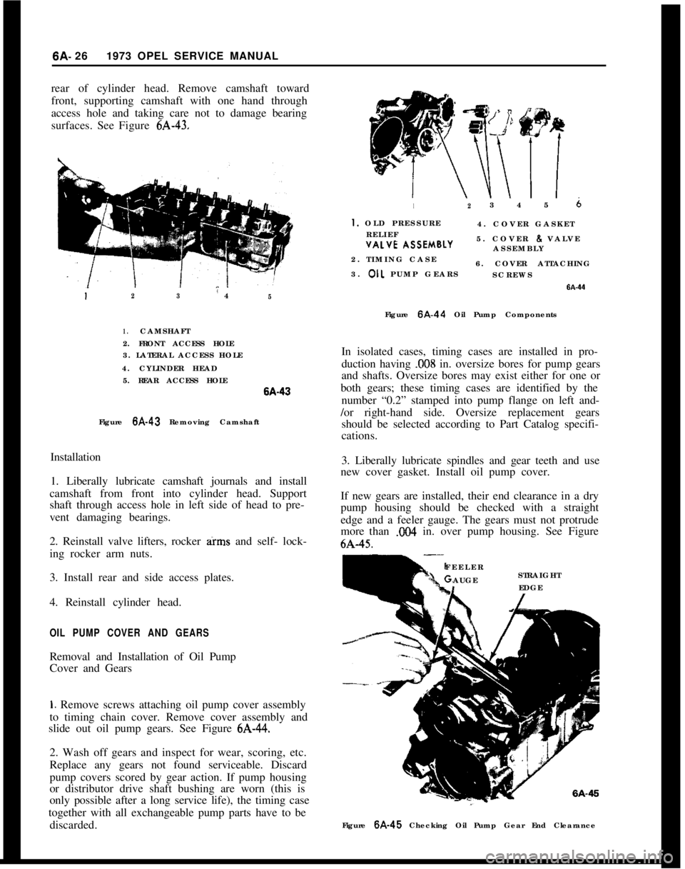
rear of cylinder head. Remove camshaft toward
front, supporting camshaft with one hand through
access hole and taking care not to damage bearing
surfaces. See Figure 6A-43.12345 6
I. OLD PRESSURE
4. COVER GASKET
RELIEF
~~- \SSEMBLY5. COVER 8 VALVE
ASSEMBLYVALVE I
2. TIMING CASE
6. COVER ATTACHING
3. OIL PUMP GEARS
SCREWS
123” 45Figure 6A-44 Oil Pump Components
1.CAMSHAFT
2. FRONT ACCESS HOLE
3. LATERAL ACCESS HOLE
4. CYLINDER HEAD
5. REAR ACCESS HOLEISA-43
Figure 6A-43 Removing Camshaft
Installation
1. Liberally lubricate camshaft journals and install
camshaft from front into cylinder head. Support
shaft through access hole in left side of head to pre-
vent damaging bearings.
2. Reinstall valve lifters, rocker arms and self- lock-
ing rocker arm nuts.
3. Install rear and side access plates.
4. Reinstall cylinder head.
OIL PUMP COVER AND GEARSRemoval and Installation of Oil Pump
Cover and Gears
1. Remove screws attaching oil pump cover assembly
to timing chain cover. Remove cover assembly and
slide out oil pump gears. See Figure 6A-44.
2. Wash off gears and inspect for wear, scoring, etc.
Replace any gears not found serviceable. Discard
pump covers scored by gear action. If pump housing
or distributor drive shaft bushing are worn (this is
only possible after a long service life), the timing case
together with all exchangeable pump parts have to be
discarded.In isolated cases, timing cases are installed in pro-
duction having
.008 in. oversize bores for pump gears
and shafts. Oversize bores may exist either for one or
both gears; these timing cases are identified by the
number “0.2” stamped into pump flange on left and-
/or right-hand side. Oversize replacement gears
should be selected according to Part Catalog specifi-
cations.
3. Liberally lubricate spindles and gear teeth and use
new cover gasket. Install oil pump cover.
If new gears are installed, their end clearance in a dry
pump housing should be checked with a straight
edge and a feeler gauge. The gears must not protrude
more than X04 in. over pump housing. See Figure6A-45.
FEELER
AUGESTRAIGHTIEDGE
Figure 6A-45 Checking Oil Pump Gear End Clearance
Page 318 of 625
ENGINE MECHANICAL AND MOUNTS6A- 27
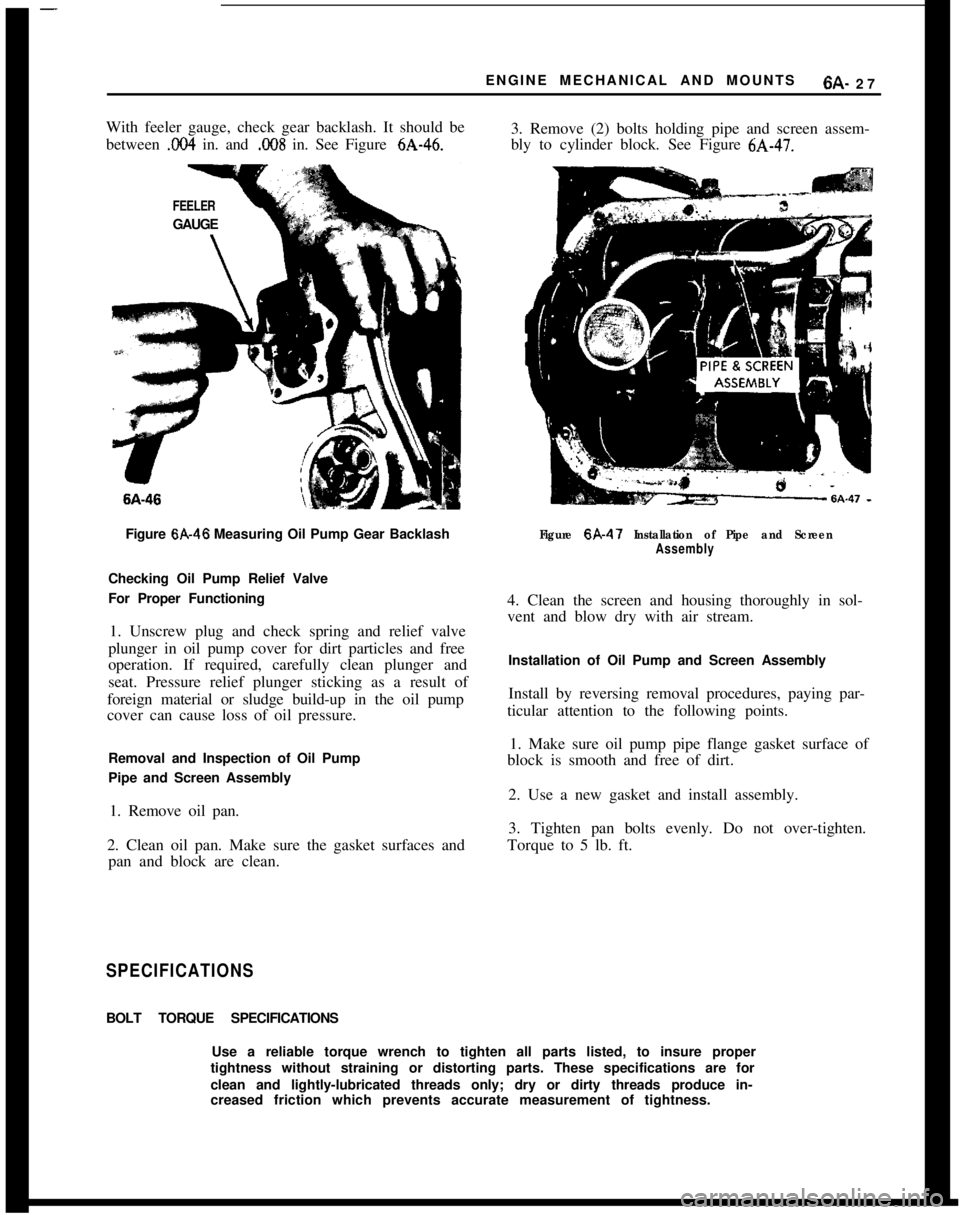
With feeler gauge, check gear backlash. It should be
between
.I?04 in. and .C!OS in. See Figure 6A-46.3. Remove (2) bolts holding pipe and screen assem-
bly to cylinder block. See Figure 6A-47.
FEELERGAUGE6A-46
Figure 6A-46 Measuring Oil Pump Gear Backlash
Checking Oil Pump Relief Valve
For Proper Functioning
1. Unscrew plug and check spring and relief valve
plunger in oil pump cover for dirt particles and free
operation. If required, carefully clean plunger and
seat. Pressure relief plunger sticking as a result of
foreign material or sludge build-up in the oil pump
cover can cause loss of oil pressure.
Removal and Inspection of Oil Pump
Pipe and Screen Assembly
1. Remove oil pan.
2. Clean oil pan. Make sure the gasket surfaces and
pan and block are clean.
Figure 6A-47 Installation of Pipe and Screen
Assembly4. Clean the screen and housing thoroughly in sol-
vent and blow dry with air stream.
Installation of Oil Pump and Screen Assembly
Install by reversing removal procedures, paying par-
ticular attention to the following points.
1. Make sure oil pump pipe flange gasket surface of
block is smooth and free of dirt.
2. Use a new gasket and install assembly.
3. Tighten pan bolts evenly. Do not over-tighten.
Torque to 5 lb. ft.
SPECIFICATIONSBOLT TORQUE SPECIFICATIONS
Use a reliable torque wrench to tighten all parts listed, to insure proper
tightness without straining or distorting parts. These specifications are for
clean and lightly-lubricated threads only; dry or dirty threads produce in-
creased friction which prevents accurate measurement of tightness.
Page 323 of 625
66.321973 OPEL SERVICE MANUAL
COOLING SYSTEM
CONTENTS
Subject
DESCRIPTION AND OPERATION:
Cooling System and Water Pump
. . . . . . . . . . . . . . . . . . . . . . . . . . . . . . . .DIAGNOSIS: (Not Applicable)
MAINTENANCE AND ADJUSTMENTS:
Checking and Filling Cooling System
. . . . . . . . . . . . . . . . . . . . . . . .Draining
andFlushingCoolingSystem. . . . . . . . . . . . . . . . . . . . . .Conditioning the Cooling System
. . . . . . . . . . . . . . . . . . . . . . . . . . . . . . . .Using and Testing Anti-Freeze Solutions
. . . . . . . . . . . . . . . . . .Fan Belt Adjustment or Replacement
. . . . . . . . . . . . . . . . . . . . . . . .Radiator Thermostat Inspection and Test
. . . . . . . . . . . . . . . .MAJOR REPAIR:
Water Pump Removal
. . . . . . . . . . . . . . . . . . . . . . . . . . . . . . . . . . . . . . . . . . . . . . . . . . . . .Radiator
Removal. . . . . . . . . . . . . . . . . . . . . . . . . . . . . . . . . . . . . . . . . . . . . . . . . . . . . . . . . . . . . .SPECIFICATIONS:
Cooling System Capacities
. . . . . . . . . . . . . . . . . . . . . . . . . . . . . . . . . . . . . . . . . . . .Page No.
68-32
6B-32
68-32
68-33
68-33
68-33
68-33
68-34
68-34
6B-35
DESCRIPTION AND OPERATION
COOLING SYSTEM AND WATER PUMPThe coiling system is of the conventional pressurized
type. A centrifugal pump arranged in timing case
serves to circulate the coolant.
When the thermostat is closed, the coolant will re-
turn to the pump via a by-pass for swift and uniform
warming up of the engine the coolant circulates
through the radiator, only when the engine has
reached normal operating temperature.
The heater system branches off the cooling system
ahead of thermostat in flow direction so that the
heater is in operation before engine has reached full
operating temperature.
MAINTENANCE AND ADJUSTMENTS
Checking and Filling Cooling SystemThe coolant level should be checked only when the
engine is cold and only enough coolant should be
added to bring the level halfway between core andtank top. It is unnecessary and undesirable to remove
the radiator cap and check the coolant level each
time the car stops at a filling station for gasoline or
oil, since the engine is usually hot at such times.
WARNING: Never remove the radiator cap quickly
when engine is HOT Sudden release of cooling
sys-
tern pressure may cause the coolant to boil and some
of it may be ejected from the radiator
filler neck,
resulting in
inl’ury to persons or damage to the car
finish.If it is necessary at any time to remove the radiator
cap when engine is hot, rotate the cap counterclock-
wise until first stop is reached. Leave cap in this
position until all pressure in cooling system has been
released, then turn cap past the first stop and remove
it.
Draining and Flushing
Cooling SystemThe cooling system should be completely drained
and the recommended coolant installed every two (2)
years.To drain the cooling system, remove radiator cap,
remove lower radiator hose from the lower tank and
Page 357 of 625
6G- 661973 OPEL SERVICE MANUAL
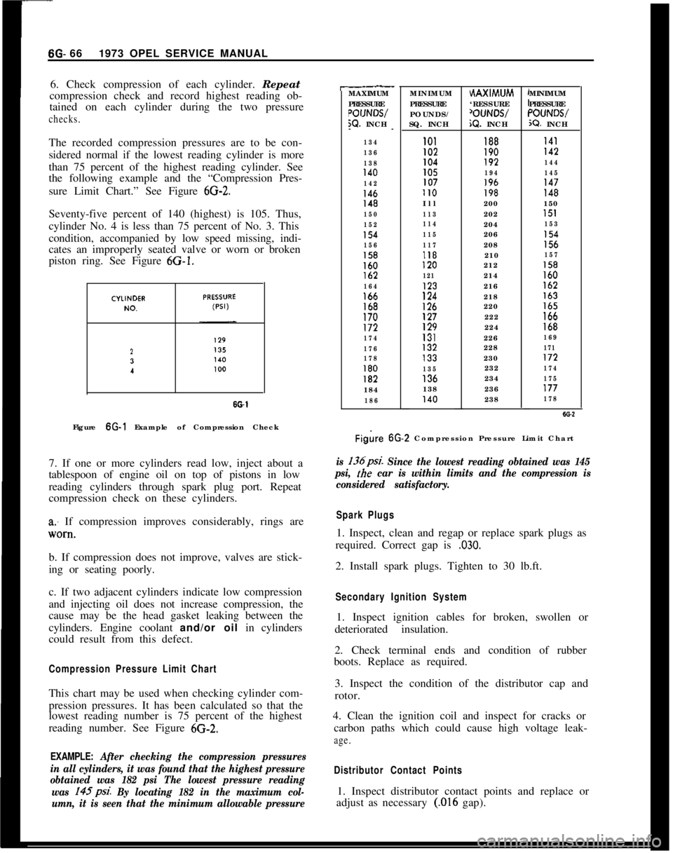
6. Check compression of each cylinder. Repeat
compression check and record highest reading ob-
tained on each cylinder during the two pressurechecks.The recorded compression pressures are to be con-
sidered normal if the lowest reading cylinder is more
than 75 percent of the highest reading cylinder. See
the following example and the “Compression Pres-
sure Limit Chart.” See Figure
6G-2.Seventy-five percent of 140 (highest) is 105. Thus,
cylinder No. 4 is less than 75 percent of No. 3. This
condition, accompanied by low speed missing, indi-
cates an improperly seated valve or worn or broken
piston ring. See Figure 6G-1.
23
I
SO-1Figure 6G-1 Example of Compression Check
7. If one or more cylinders read low, inject about a
tablespoon of engine oil on top of pistons in low
reading cylinders through spark plug port. Repeat
compression check on these cylinders.
a: If compression improves considerably, rings are
lV0*tl.b. If compression does not improve, valves are stick-
ing or seating poorly.
c. If two adjacent cylinders indicate low compression
and injecting oil does not increase compression, the
cause may be the head gasket leaking between the
cylinders. Engine coolant and/or oil in cylinders
could result from this defect.
Compression Pressure Limit ChartThis chart may be used when checking cylinder com-
pression pressures. It has been calculated so that the
lowest reading number is 75 percent of the highest
reading number. See Figure 6G-2.
EXAMPLE: After checking the compression pressures
in all cylinders, it was found that the highest pressure
obtained was 182 psi The lowest pressure reading
was 145psi.
By locating 182 in the maximum col-
umn, it is seen that the minimum allowable pressure
r-.__MAXIMUM
PRESSURE
POIJNWW. INCH
--
134
136
138
140
142
146148
150
152
154
156
158160lb2
164166168170172
174
176
178
180182184
186MINIMUM
PRESSURE
POUNDS/
SQ. INCHHAXIMUM
‘RESSURE
‘OUNWiQ. INCHMINIMUM
PRESSURE“OUNWX?. INCH
101188I41I02190142104192144105194145107196147II0198148Ill200150
113202151
114204153
115206154
117208156118210157120212158
121214160123216162
124218163
126220165127222166129224168131226169132228171133230172
135232174136234175138236177140238178
Figire 6G.2 Compression Pressure Limit Chart
is 136psi. Since the lowest reading obtained was 145
psi,
the car is within limits and the compression is
considered satisfactory.
Spark Plugs1. Inspect, clean and regap or replace spark plugs as
required. Correct gap is
,030.2. Install spark plugs. Tighten to 30 lb.ft.
Secondary Ignition System1. Inspect ignition cables for broken, swollen or
deteriorated insulation.
2. Check terminal ends and condition of rubber
boots. Replace as required.
3. Inspect the condition of the distributor cap and
rotor.
4. Clean the ignition coil and inspect for cracks or
carbon paths which could cause high voltage leak-
age.
Distributor Contact Points1. Inspect distributor contact points and replace or
adjust as necessary
(.016 gap).
Page 358 of 625
2. If inspection of contact points indicates excessive
burning, pitting or wear, check condenser and re-
place if necessary.
3. Inspect all connections and wires in the primary
ignition circuit. Correct any abnormal conditions
found.Carburetor1. Clean fuel strainer in fuel pump. To prevent fuel
leakage in pump, disconnect “IN” line from pump
and raise end above fuel level. The in-line fuel filter
should be replaced every 12,000 miles or every 12
months.
2. Check for freedom of choke valve operation and
clean shaft if necessary, with suitable solvent.
3. Inspect throttle cable or linkage bracket and re-
turn spring for wear. With helper depressing acceler-
ator pedal to floor, check for wide open throttle.
Adjust accelerator pedal height so wide open throttle
is obtained when pedal is within
l/2 inch from floor.
Lubricate linkage pivot points with engine oil.
Air CleanerCheck paper element every 6,000 miles and replace
every
24,ooO miles. If a vehicle is operated in dusty
territory, check condition of air cleaner element
more frequently and replace if necessary.
Fan Belt1. Inspect belt for wear, cracks or frayed points.
Replace and/or adjust as necessary. Specified ten-
sion for belt using Gauge J-23600 is 45 lbs.
Cooling System1. Inspect the radiator, water pump, cylinder head
areas and all radiator and heater hose connections
for evidence of engine coolant leaks.
2. Inspect all hoses for deterioration from gas and oil
contact. Correct as required.
Inspection should be made with engine operating at
normal temperature, cooling system completely
filled, temperature control lever fully open and nor-
mal pressure in the system. Normal pressure should
be 13.2 to 15.2 psi.
Engine Lubrication SystemInspect engine for evidence of oil leakage. Correctany abnormal condition with sealastic or new seals
and gaskets.
Battery
1. Inspect battery, battery mount and cables and
check electrolyte level. Proper level should be just
above the cell plates.
CAUTION:Do not over fill.
2. Determine the serviceability of the battery by ap-
plying the 421 Battery Test.
Positive Crankcase VentilationClean crankcase ventilator metered orifice in the in-
take manifold fitting every 6,000 miles. Also all hoses
and fittings should be inspected, cleaned and re-
placed, if necessary.
To clean, remove rubber hose from metered orifice
and apply air pressure to orifice to remove any for-
eign particles that may be trapped.
Valve Lifter AdjustmentRefer to Engine Mechanical and Mounts section for
valve lifter adjustment procedure.
Engine Tune-Up Instrument ChecksThe following instrument checks and adjustments
serve as a final check on engine condition. These
checks may discover some new problems that may
not have been obvious before. The engine is also
given its final adjustments that will assure maximum
performance, reliability, and proper emission con-
trol.
Refer to Electrical Group for checking procedures of
the following:
Cranking Voltage Check
Ignition Timing
Distributor Advance
Ignition Output
Secondary Resistance
Current Output and Voltage Setting
Idle Speed and Mixture AdjustmentsRefer to carburetor section.
Page 397 of 625

7C- 361973 OPEL SERVICE MANUAL
CONTENTS
Subject
DESCRIPTION AND OPERATION:
Description of the Opel Three-Speed Automatic,Transmission....................................................................
Principles of Operation....................................................
ComponentOperation
andLocation............................
Mechanical Operation......................................................
Hydraulic Control Units and Valves............................H,y&aulic Operation..........................................................
DIAGNOSIS:
Sequence for Trouble Diagnosis..................................
Checking
Procedures........................................................
ExternalOil
Leaks..............................................................
Trouble
DiagnosisChart..................................................
Hydraulic Pressure
Checks............................................
MAINTENANCE AND ADJUSTMENTS:
Detent Cable Adjustment..............................................
ServicingSelector
Lever..................................................
MAJOR REPAIR:
Transmission Removal and Installation
AllModels........................................................................
Removalof
OilPan............................................................
RemovalofValveBody....................................................
Removalof
ServoPiston................................................
Removalof
Selector
LeverandShaft........................
RemovalofModulatorAssembly..................................
RemovalofDetentValveAssembly............................
RemovalofExtensionHousing......................................
Removal of Speedometer Drive Gear, Governor
Body and Governor Hub..............................................
Removal of Converter Housing, Oil Pump, Reverse
and Second Clutch Assembly..................................
Removal of Third Clutch Assembly, Planetary
Carrier Assembly, Reaction Sun Gear and Drum
Assembly and Low Bank............................................
Disassembly, Inspection and Reassembly of
Converter Housing, Oil Pump and Reverse Clutch
Disassembly, Inspection and Reassembly of
SecondClutch
................................................................
Disassembly, Inspection and Reassembly of
ThirdClutch....................................................................
Disassembly, Inspection and Reassembly of
Planetary Carrier
............................................................Page No.7c- 377c- 387c- 447c- 487c- 487c- 64
7C- 81
7C- 81IC- 817c- 827c- 877c- 917c- 937c- 947c- 99.7c- 99
7c-1007c-loo
7&l 01
7c-102
7c-102
7c-103
7c-103
7c-104
7c-105
7c-111
7c-114
7c-118
Page 442 of 625
DIAGNOSIS
SEQUENCE
1. Check and correct oil level. Refer to Specifications
for checking and refill procedures.
2. Check and correct vacuum line and fittings.
3. Check and correct manual linkage.
4. Road test car using all selective ranges, noting
when discrepancies in operation occur.
5. If engine performances indicates an engine tuneup
is required, this should be performed before road
testing is completed or transmission correction at-
tempted. Poor engine performance can result in
rough shifting or other malfunctions.
CHECKING PROCEDURESBefore diagnosis of any transmission complaint is
attempted, there must be an understanding of oil
checking procedure and what appearance the oil
should have. Many times a transmission malfunction
can be traced to low oil level, improper reading of
dipstick, or oil appearances; therefore, a careful anal-
ysis of the condition of oil and the level may elimi-
nate needless repairs.
When checking oil level in the Opel Three Speed
Automatic Transmission, the procedure outlined in
Specifications should be followed to obtain the most
accurate reading.
Also when the dipstick is removed, it should be noted
whether the oil is devoid of air bubbles or not. Oil
with air bubbles gives an indication of an air leak in
the suction lines, which can cause erractic operation
and slippage. Water in the oil imparts a milky, pink
cast to the oil and can cause spewing.
EXTERNAL OIL LEAKS
Determining source of oil leakBefore attempting to correct an oil leak, the actual
source of the leak must be determined. In many
cases, the source of the leak can be deceiving due to
“wind flow” around the engine and transmission.
The suspected area should be wiped clear of all oil
before inspecting for the source of the leak. Red dyeAUTOMATIC TRANSMISSION 7C- 81
is used in the transmission oil at the assembly plant
and will indicate if the oil leak is from the transmis-
sion.The use of a “Black Light” to locate the point at
which the oil is leaking is helpful. Comparing the oil
from the leak to that on the engine or transmission
dipstick, when viewed by Black Light, will determine
the source of the leak-engine or transmission.
Oil leaks around the engine and transmission are
generally carried toward the rear of the car by air
stream. For example, a transmission oil filler tube to
case leak will sometimes appear as a leak at the rear
of the transmission. In determining the source of a
leak, proceed as follows:
1. Degrease underside of transmission.
2. Road test to get unit at operating temperature.
3. Inspect for leak with engine running.
4. With engine off, check for oil leaks due to the
raised oil level caused by drain back.
Case Porosity RepairOpel Three-Speed Automatic Transmission external
oil leaks caused by case porosity can be successfully
repaired with the transmission in the car by using the
following recommended procedures:
1. Road test and bring the transmission to operating
temperature, approximately 180 degrees F.
2. Raise car on a hoist or jack stand, engine running,
and locate source of oil leak. Check for oil leaks in
low, drive, and reverse.
3. Shut engine off and thoroughly clean area to be
repaired with a suitable cleaning solvent and a
brush- air dry. A clean, dry soldering acid brush can
be used to clean the area and also to apply the epoxy
cement.
4. Using instructions of the manufacturer, mix a suf-
ficient amount of epoxy, BUICK Group 0.423, Part
No. 1360016, or equivalent, to make the repair. Ob-
serve cautions of manufacturer in handling.
5. While the transmission case is still HOT, apply the
epoxy to the area to be repaired. Make certain the
area to be repaired is fully covered.
6. Allow cement to cure for 3 hours before starting
engine.
7. Road test and check for leaks.
Page 486 of 625

AUTOMATIC TRANSMISSION 7C-1251. CASE VENT4.3RD CLUTCH7.SUCTION
2. CONVERTER OUT5MODULATOR8.LINE/3.2ND CLUTCH
6. BOOST9.REVERSEFigure 7C-202 Case Front View Oil Passage
Identification
7.
!nspect reaction sun gear drum bushing sleeve
inside case at rear for scoring. If necessary, replace
sleeve before installing rear case bushing.
8. Remove sleeve by grinding. Care must be used in
order that aluminum case is not damaged when
grinding sleeve.
9. Install new sleeve using installer tool J-23130-7
and driver handle J-8092.
10. Install new case bushing using remover and in-
staller tool J-23130-3 and driver handle J-8092.
Bushing should be installed flush with case at rear.
See Figure
7C-203.Figure 7C-2031. Drain Converter. If clutch disc material or
foreign matter has been found while draining con-
verter,
replace entire converter assembly as it can not be
cleaned properly.
2. Air check converter for leaks using converter
checking tool J-21369. Install tool and tighten. Ap-
ply 80 psi air pressure to tool. See Figure
7C-204.Figure 7C-204
3. Submerge in water and check for leaks.
4. Check converter hub surfaces for scoring or wear.
Installation of Selector Lever and Shaft1. Install new selector lever shaft oil seal in case.
Insert selector lever shaft through case from outside.
Care should be exercised so that oil seal is not da-
maged. See Figure
7C-206.2. Insert spring pin in case to secure selector lever
shaft.3. Guide selector lever over shaft and secure with
lock nut.
4. Insert parking
paw1 actuator rod from front of the
case and through hole in case at rear. See Figure 7C-
207.5. Install parking
paw1 actuator rod retaining ring.
Installation of Low Band1. Turn transmission case so that front of case is
upward.
Page 495 of 625
7C-1341973 OPEL SERVICE MANUAL
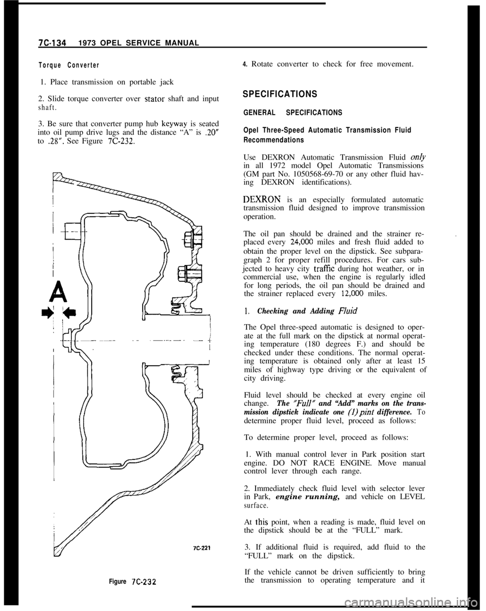
Figure 7C-232
Torque Converter4. Rotate converter to check for free movement.
1. Place transmission on portable jack
2. Slide torque converter over stator shaft and input
shaft.3. Be sure that converter pump hub keyway is seated
into oil pump drive lugs and the distance “A” is
.20”to
.28”. See Figure 7C-232.
SPECIFICATIONS
GENERAL SPECIFICATIONS
Opel Three-Speed Automatic Transmission Fluid
RecommendationsUse DEXRON Automatic Transmission Fluid on/y
in all 1972 model Opel Automatic Transmissions
(GM part No. 1050568-69-70 or any other fluid hav-
ing DEXRON identifications).DEXIRON is an especially formulated automatic
transmission fluid designed to improve transmission
operation.
The oil pan should be drained and the strainer re-
placed every
24,ooO miles and fresh fluid added to
obtain the proper level on the dipstick. See subpara-
graph 2 for proper refill procedures. For cars sub-
jected to heavy city
traff%z during hot weather, or in
commercial use, when the engine is regularly idled
for long periods, the oil pan should be drained and
the strainer replaced every
12,ooO miles.
.
1.Checking and Adding FluidThe Opel three-speed automatic is designed to oper-
ate at the full mark on the dipstick at normal operat-
ing temperature (180 degrees F.) and should be
checked under these conditions. The normal operat-
ing temperature is obtained only after at least 15
miles of highway type driving or the equivalent of
city driving.
Fluid level should be checked at every engine oil
change.
The “FuIl” and “Add” marks on the trans-
mission dipstick indicate one (1)pint
difference. Todetermine proper fluid level, proceed as follows:
To determine proper level, proceed as follows:
1. With manual control lever in Park position start
engine. DO NOT RACE ENGINE. Move manual
control lever through each range.
2. Immediately check fluid level with selector lever
in Park, engine running, and vehicle on LEVEL
surface.At
t,his point, when a reading is made, fluid level on
the dipstick should be at the “FULL” mark.
3. If additional fluid is required, add fluid to the
“FULL” mark on the dipstick.
If the vehicle cannot be driven sufficiently to bring
the transmission to operating temperature and it