ESP OPEL GT-R 1973 Owner's Guide
[x] Cancel search | Manufacturer: OPEL, Model Year: 1973, Model line: GT-R, Model: OPEL GT-R 1973Pages: 625, PDF Size: 17.22 MB
Page 305 of 625
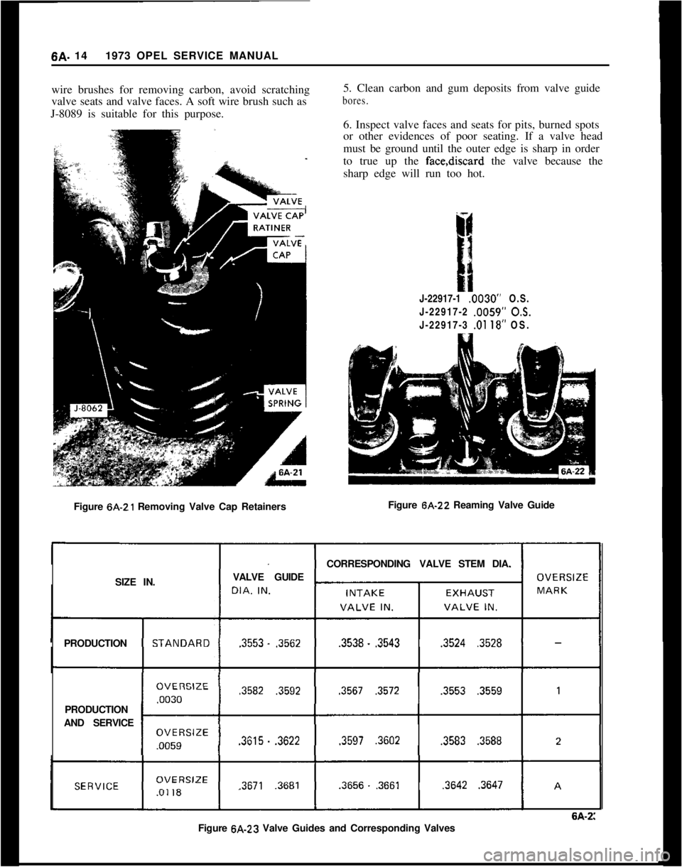
6A. 141973 OPEL SERVICE MANUAL
wire brushes for removing carbon, avoid scratching
valve seats and valve faces. A soft wire brush such as
J-8089 is suitable for this purpose.
Figure 6A-21 Removing Valve Cap Retainers5. Clean carbon and gum deposits from valve guide
bores.6. Inspect valve faces and seats for pits, burned spots
or other evidences of poor seating. If a valve head
must be ground until the outer edge is sharp in order
to true up the face,discard the valve because the
sharp edge will run too hot.
J-22917-1 .0030” O.S.
J-22917-2 .0059”
05.J-22917-3 .Ol 18” OS.
Figure 6A-22 Reaming Valve Guide
CORRESPONDINGVALVE STEM DIA.
SIZE IN.VALVE GUIDE
PRODUCTION.3553.
.3562.3538..3543.3524.3528PRODUCTION
AND SERVICE
.3582.3592.3567.3572.3553.3559.3615.
.3622.3597.3602.3583.3588
.3671.3681.3656..3661.3642.3647
6A-2:Figure 6A-23 Valve Guides and Corresponding Valves
Page 306 of 625
ENGINE MECHANICAL AND MOUNTS6A- 15New inlet valves must not be refaced or lapped with
grinding compound.The correct angle for the intake
and exhaust valve head is 44 degrees.10. Install cylinder head.
11. Adjust valve clearance. See MAINTENANCE
AND ADJUSTMENTS.
7. Inspect valve guides. Worn or pitted guides can be
reamed to accept valves with oversize stems. Over-
size valves are occasionally used in production.
Oversize valves are marked
’ 1 u “2” or “A” and are
stamped into the valve stem end and also stamped
near spark plug hole. See Figure 6A-22.
Replacing Rocker Arm Studs1. When replacing rocker arm studs become
neces-
sary, remove air cleaner, rocker arm cover and
rocker arm.
8. Reseat valve seats in cylinder head in the following
sequence:
Intake
NOTE:The rocker arm studs are screwed into the
cylinder head. A tapered part of the stem serves to
a void stud loosening.With 45 degrees cutter, remove burnt structure until
a metallic bright seat is obtained. Lightly coat valve
head with red lead, insert it into guide and turn it
under light pressure several times back and forth.
Thereby a contact pattern is obtained and the seat
width can be measured. If valve does not seat per-
fectly all around, lightly recut valve seat to the estab-
lished seat width of
,049” - .059” with 30 degrees
correction cutter.
ExhaustThe directions for reconditioning intake valve seats
apply in principle also to exhaust valve seat recondi-
tioning with the exception that the valve seat width
should be
.063-,073 in. and different cutters are em-
ployed.
NOTE:
: OTse new valve seals whenever
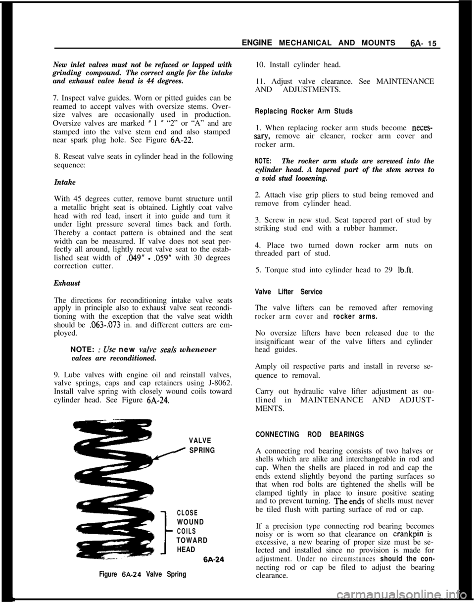
valves are reconditioned.9. Lube valves with engine oil and reinstall valves,
valve springs, caps and cap retainers using J-8062.
Install valve spring with closely wound coils toward
cylinder head. See Figure
6A-24.2. Attach vise grip pliers to stud being removed and
remove from cylinder head.
3. Screw in new stud. Seat tapered part of stud by
striking stud end with a rubber hammer.
4. Place two turned down rocker arm nuts on
threaded part of stud.
5. Torque stud into cylinder head to 29
lb.ft.
Valve Lifter ServiceThe valve lifters can be removed after removing
rocker arm cover and rocker arms.No oversize lifters have been released due to the
insignificant wear of the valve lifters and cylinder
head guides.
Amply oil respective parts and install in reverse se-
quence to removal.
Carry out hydraulic valve lifter adjustment as ou-
tlined in MAINTENANCE AND ADJUST-
MENTS.
VALVE
I SPRING
CLOSE
WOUND
COILS
TOWARD
HEAD6A-24
Figure 6A-24 Valve SpringCONNECTING ROD BEARINGSA connecting rod bearing consists of two halves or
shells which are alike and interchangeable in rod and
cap. When the shells are placed in rod and cap the
ends extend slightly beyond the parting surfaces so
that when rod bolts are tightened the shells will be
clamped tightly in place to insure positive seating
and to prevent turning. Theends of shells must never
be tiled flush with parting surface of rod or cap.
If a precision type connecting rod bearing becomes
noisy or is worn so that clearance on crankpin is
excessive, a new bearing of proper size must be se-
lected and installed since no provision is made for
adjustment. Under no circumstances should the con-necting rod or cap be filed to adjust the bearing
clearance.
Page 328 of 625
FUEL SYSTEMSC- 37
must always be removed before the distributor can be
removed.
EVAPORATION CONTROL SYSTEM1. The function of the fuel evaporation control sys-
tem is to absorb the fuel vapors developing in the fuel
tank, especially when vehicle is parked, due to at-
mospheric pressure and temperature influences, and
to release these fuel vapors during vehicle operation.
2. This system utilizes the property of the activated
carbon to absorb and expel fuel vapors. The activated
carbon container is installed on the left front side of
the engine compartment. The fuel tank has a
non-vented tiller cap. Vent hoses are joined in the area of
the tank. A plastic evaporation line leads from there
along vehicle underbody to the activated carbon con-
tainer.
3. A small tube above the throttle valve body con-
nects the carburetor to the activated carbon con-
tainer. In this way, the fuel vapor collected in the
activated carbon container is fed through the carbu-
retor into the combustion chambers during engine
operation.
4. The carburetor is provided with an internal and
outside ventilation, the activated carbon container is
also connected to the outside ventilation (only effec-
tive when engine is idling). In this way, the fuel
vapors escaping to the outside during engine idle are
collected by the activated carbon container and fed
into the combustion chambers.
5. The vent lines are connected to the upper part of
the activated carbon container. Fresh air enters
through a foam rubber filter at the lower part andflows, together with the fuel vapor, to the carburetor.
Metered bores in the hose fittings of the fuel tank
control the air
- and fuel vapor flow through the
activated carbon container to the carburetor, and the
pressure release in the fuel tank and ensure complete
purging of the carbon container.
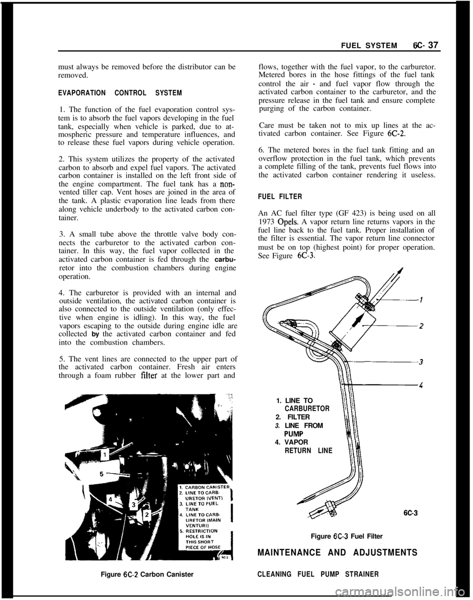
Care must be taken not to mix up lines at the ac-
tivated carbon container. See Figure
6C-2.6. The metered bores in the fuel tank fitting and an
overflow protection in the fuel tank, which prevents
a complete filling of the tank, prevents fuel flows into
the activated carbon container rendering it useless.
FUEL FILTERAn AC fuel filter type (GF 423) is being used on all
1973 Opels. A vapor return line returns vapors in the
fuel line back to the fuel tank. Proper installation of
the filter is essential. The vapor return line connector
must be on top (highest point) for proper operation.
See Figure
6C-3.1. LINE TO
CARBURETOR2. FILTER
3. LINE FROM
4. VAPOR
RETURN LINE
6C-3Figure
6C-3 Fuel Filter
MAINTENANCE AND ADJUSTMENTSFigure
6C-2 Carbon CanisterCLEANING FUEL PUMP STRAINER
Page 354 of 625
EMISSION CONTROL SYSTEMS6F- 63
2. With the engine “OFF”, observe damper doorposition through snorkel opening. If position of snor-kel makes observation difficult “se the aid of a mir-
ror. At this point damper door should be in such a
position that the heat stove passage is covered (snor-
kel passage open). If not, check for binds in linkage.3. Apply at least nine in. Hg. of vacuum to dia-
phragm assembly through hose disconnected at sen-
sor “nit. This can be done by mouth. Damper door
should completely close snorkel passage whenvacuum is applied. If not, check to see if linkage is
hooked up correctly and for a vacuum leak.
4. With vacuum applied, bend or clamp hose to trapvacuum in diaphragm assembly. Damper door
should remain in position (closed snorkel passage). Ifit does not, there is a vacuum leak in diaphragm
assembly. Replace diaphragm assembly.
Sensor Check
Quick Check of System:
1. Start test with engine cold, air cleaner at a temper-ature below 85 degrees. If the engine has been in
recent “se, allow it to cool.
2. Observe the air door before starting the engine: it
should be closed.3. Start the engine and allow it to idle. Immediately
after starting the engine, the air door should open.
4. As the engine warms up, the air door should start
to close, and the air cleaner should become warm tothe hand.
5. The system is operating normally as described
above. If the air cleaner fails to operate as above or
if correct operation of the air cleaner is still in doubt,
proceed to the thermometer check.
Thermometer Check of Sensor:1. Start test with air cleaner temperature below 85
degrees. IF ENGINE HAS BEEN RUN RE-
CENTLY, ALLOW IT TO COOL DOWN. Whileengine is cooling, remove air cleaner cover and in-
stall a temperature gage such as J- 22973 as close as
possible to
se&r. Keinstall air cleaner cover. Let car
stand idle for
l/2 hour or more before proceeding to
step 2.2. Start the engine. Air door should open immedi-
ately if engine is cool enough. When air door starts
to close (in a few minutes), remove air cleaner cover
and read temperature gage. It must
read 115 degreesplus or minus 20 degrees.
3. If air door does not start to close at temperatureindicated, temperature sensor is defective and must
be replaced.
EXHAUST GAS RECIRCULATION SYSTEM
TestingThe exhaust gas recirculation valve is to be checked
at 12,000 mile intervals “sing the following proce-
dure:1. With engine at operating temperature, connect a
tachometer to engine and note R.P.M. at idle.
2. Disconnect vacuum hose at the intake manifold
that goes to the air cleaner.
3. Disconnect vacuum hose for exhaust gas recircula-tion valve from the throttle valve and connect it to
the intake manifold where vacuum hose to air
cleaner was connected.4. Engine speed should decrease between
100-240R.P.M. from previously noted R.P.M.
5. If the R.P.M. decrease is less than 100 R.P.M., theexhaust gas recirculation valve and fitting going into
the intake manifold must be removed, cleaned, and’
reinstalled.
MAINTENANCE AND ADJUSTMENTS
EXHAUST GAS RECIRCULATION SYSTEM
CleaningClean the exhaust gas recirculation valve and fitting
with a piece of stiff wire removing all exhaust depos-
its.
CAUTION:Do not soak in solvent. After
r.einstafIing the valve and fitting, check op
eration as outlined under “Testing”. If
vahe does not operate properly after a
thorough cleaning, replace it.
MAJOR REPAIR
REMOVAL AND REPLACEMENT OECS UNITSThe damper door is not serviceable. The air cleaner
assembly must be replaced if the damper door is
defective.
R And R Vacuum Motor
1. Remove vacuum
motor retainer spring. See Figure
6F-5.
Page 357 of 625
6G- 661973 OPEL SERVICE MANUAL
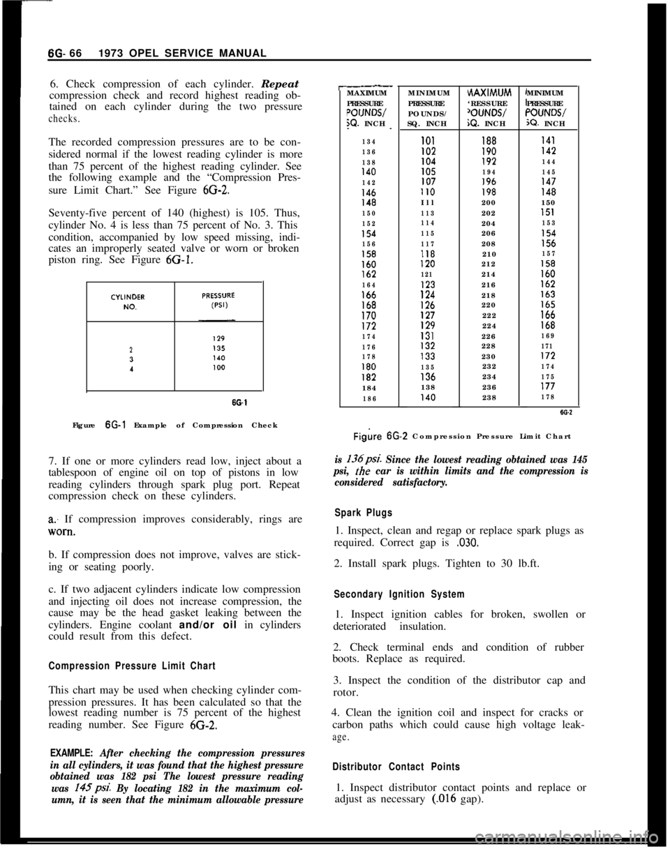
6. Check compression of each cylinder. Repeat
compression check and record highest reading ob-
tained on each cylinder during the two pressurechecks.The recorded compression pressures are to be con-
sidered normal if the lowest reading cylinder is more
than 75 percent of the highest reading cylinder. See
the following example and the “Compression Pres-
sure Limit Chart.” See Figure
6G-2.Seventy-five percent of 140 (highest) is 105. Thus,
cylinder No. 4 is less than 75 percent of No. 3. This
condition, accompanied by low speed missing, indi-
cates an improperly seated valve or worn or broken
piston ring. See Figure 6G-1.
23
I
SO-1Figure 6G-1 Example of Compression Check
7. If one or more cylinders read low, inject about a
tablespoon of engine oil on top of pistons in low
reading cylinders through spark plug port. Repeat
compression check on these cylinders.
a: If compression improves considerably, rings are
lV0*tl.b. If compression does not improve, valves are stick-
ing or seating poorly.
c. If two adjacent cylinders indicate low compression
and injecting oil does not increase compression, the
cause may be the head gasket leaking between the
cylinders. Engine coolant and/or oil in cylinders
could result from this defect.
Compression Pressure Limit ChartThis chart may be used when checking cylinder com-
pression pressures. It has been calculated so that the
lowest reading number is 75 percent of the highest
reading number. See Figure 6G-2.
EXAMPLE: After checking the compression pressures
in all cylinders, it was found that the highest pressure
obtained was 182 psi The lowest pressure reading
was 145psi.
By locating 182 in the maximum col-
umn, it is seen that the minimum allowable pressure
r-.__MAXIMUM
PRESSURE
POIJNWW. INCH
--
134
136
138
140
142
146148
150
152
154
156
158160lb2
164166168170172
174
176
178
180182184
186MINIMUM
PRESSURE
POUNDS/
SQ. INCHHAXIMUM
‘RESSURE
‘OUNWiQ. INCHMINIMUM
PRESSURE“OUNWX?. INCH
101188I41I02190142104192144105194145107196147II0198148Ill200150
113202151
114204153
115206154
117208156118210157120212158
121214160123216162
124218163
126220165127222166129224168131226169132228171133230172
135232174136234175138236177140238178
Figire 6G.2 Compression Pressure Limit Chart
is 136psi. Since the lowest reading obtained was 145
psi,
the car is within limits and the compression is
considered satisfactory.
Spark Plugs1. Inspect, clean and regap or replace spark plugs as
required. Correct gap is
,030.2. Install spark plugs. Tighten to 30 lb.ft.
Secondary Ignition System1. Inspect ignition cables for broken, swollen or
deteriorated insulation.
2. Check terminal ends and condition of rubber
boots. Replace as required.
3. Inspect the condition of the distributor cap and
rotor.
4. Clean the ignition coil and inspect for cracks or
carbon paths which could cause high voltage leak-
age.
Distributor Contact Points1. Inspect distributor contact points and replace or
adjust as necessary
(.016 gap).
Page 384 of 625
MANUAL TRANSMISSION70.235. Attach clutch cable.
6. Perform clutch lash adjustment. See Clutch, Sec-
tions A and B for adjustment procedure.
7. After overhaul of transmission, refill with
2- l/2pints of SAE 80 or SO-90 multi-purpose gear Iubri-
cant.
REMOVING AND INSTALLING SPEED0 DRIVEN
GEAR
(WITH TRANSMISSION REMOVED)
Removing Speedo Driven Gear Assembly1. Use wrench to unscrew speed0 angular drive hold-
ing nut and remove speedo angular drive.
2. With Special Tool J-22926 and Slide Hammer
J-7004- 1, remove speedo driven gear lock pin which
retains speed0 driven gear assembly in transmission
case extension housing.
3. Using Special Tool J-22929 and Slide Hammer
J-7004- 1, remove speed0 driven gear assembly. Tool
J-2292? screws onto the speedo driven gear guide
making it possible to remove the guide and assembly
without damage to the transmission case extension
housing.
Installation of Speedo Driven Gear Assembly1. Using Special Tool J-22929 install speedo driven
gear assembly into transmission case extension hous-
ing. It may be necessary to tap lightly on tool
J-22929 when installing assembly. Be sure speedo
driven gear lock pin hole on guide lines up with hole
in transmission case extension housing. Also, rotate
mainshaft at output end when inserting speed0
driven gear assembly to insure that driven gear
meshes properly with speed0 drive gear on main-
shaft.2. Install speed0 driven gear lock pin into transmis-
sion case extension housing by tapping pin lightly.
3. Install speed0 angular drive by tightening speedo
angular drive to holding nut.
REPLACING BUSHING IN SELECTOR LEVER
(TRANSMISSION AND GEARSHIFT LINKAGE
REMOVED)
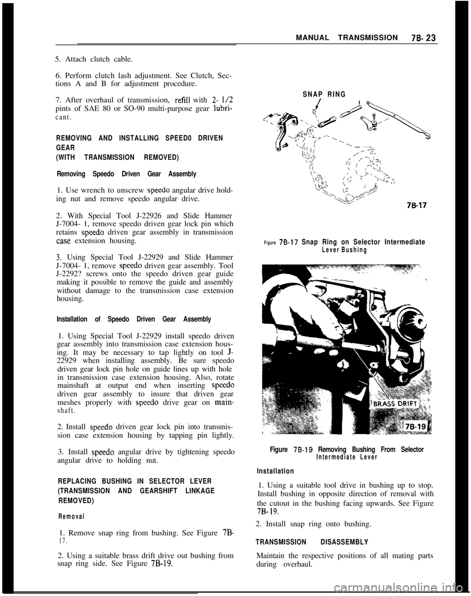
Removal1. Remove snap ring from bushing. See Figure 7B-
17.2. Using a suitable brass drift drive out bushing from
snap ring side. See Figure
7B-19.SNAP RING
Figure 78.17 Snap Ring on Selector Intermediate
Lever Bushing
Figure 78.19 Removing Bushing From SelectorIntermediate Lever
Installation1. Using a suitable tool drive in bushing up to stop.
Install bushing in opposite direction of removal with
the cutout in the bushing facing upwards. See Figure7B-
19.2. Install snap ring onto bushing.
TRANSMISSION DISASSEMBLYMaintain the respective positions of all mating parts
during overhaul.
Page 387 of 625
78.261973 OPEL SERVICE MANUAL
4. Remove both first and second speed shifter yoke
and shifter shaft cam.
Removing Main Drive Gear and Mainshaft
Assembly
1. From front of transmission, pull main drive gear
and needle bearing out of transmission. (May be
necessary to rock main drive gear.)
2. From rear of transmission, pull mainshaft assem-
bly and transmission case extension housing out of
transmission. Gear shifter sleeve will be pulled off
gear shifter sleeve carrier by the third and fourth
speed shifter yoke. Remove sleeve from yoke and
keep sleeve with mainshaft assembly. (Make sure
third and fourth speed shoes are not lost.)
Removing Third and Fourth Gear Shifter Shaft.
1. With main shaft assembly out of transmission
case, drive third and fourth gear shifter shaft out
through hole in front of case with brass drift from
rear of transmission through mainshaft assembly
hole in case.
2. Remove third and fourth speed yoke.
Removing Reverse Gear Shifter Shaft and Reverse
Idler Gear
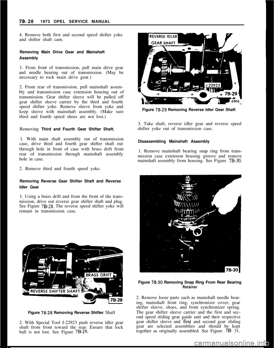
1. Using a brass drift and from the front of the trans-
mission, drive out reverse gear shifter shaft and plug.
See Figure
7B-28. The reverse speed shifter yoke will
remain in transmission case.
Figure 78.28 Removing Reverse Shifter Shaft
2. With Special Tool J-22923 push reverse idler gear
shaft from front toward the rear. Ensure that lock
ball is not lost. See Figure
7B-29.Figure 78.29 Removing Reverse Idler Gear Shaft
3. Take shaft, reverse idler gear and reverse speed
shifter yoke out of transmission case.
Disassembling Mainshaft Assembly
1. Remove mainshaft bearing snap ring from trans-
mission case extension housing groove and remove
mainshaft assembly from housing. See Figure
7B-30.Figure 78-30 Removing Snap Ring From Rear Bearing
Retainer2. Remove loose parts such as mainshaft needle bear-
ing, mainshaft front ring, synchronizer cover, gear
shifter sleeve, shoes, and front synchronizer spring.
The gear shifter sleeve carrier and the first and sec-
ond speed sliding gear guide unit and their respective
gear shifter sleeve and first and second gear sliding
gear are selected assemblies and should be kept
together as originally assembled. See Figure 7B- 31.
Page 388 of 625
MANUAL TRANSMISSION78-27
SYNCHRONIZER
SPAZER RINGf&31Figure 78.31
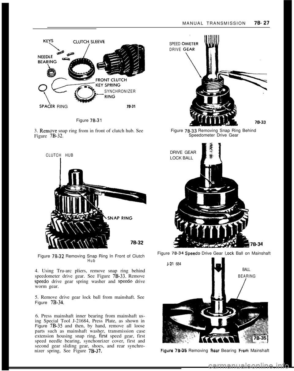
3. Remow snap ring from in front of clutch hub. See
Figure
7B-32.
SPEED
DRIVEFigure 78.33 Removing Snap Ring Behind
Speedometer Drive Gear
CLUTCH HUBFigure
7%.32 Removing Snap Ring In Front of ClutchHub4. Using Tru-arc pliers, remove snap ring behind
speedometer drive gear. See Figure
7B-33. Removespeedo drive gear spring washer and speed0 drive
worm gear.
5. Remove drive gear lock ball from mainshaft. See
Figure
7B-34.6. Press mainshaft inner bearing from mainshaft us-
ing Special Tool J-21684, Press Plate, as shown in
Figure 7B-35 and then, by hand, remove all loose
parts such as mainshaft washer, transmission case
extension housing snap ring, first speed gear, first
speed needle bearing, synchonrizer cover, first and
second gear sliding gear, shoes, and rear synchro-
nizer spring, See Figure
7B.370DRIVE GEAR
LOCK BALL
Figure 78.34
Speedo Drive Gear I.ock Ball on Mainshaft
l-21 684
BALL
BEARING
/
Figure 78.36 Removing Rest Bearing Frotii Mainshaft
Page 409 of 625
7C- 481973 OPEL SERVICE MANUAL
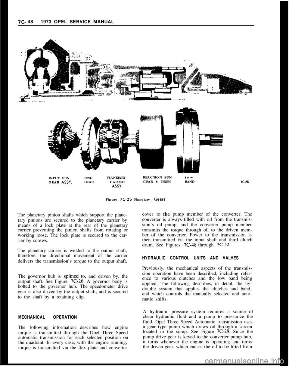
INPUT SUNRING
GEAR ASSY.GEARPLANETARY
CARRIERASSY.REACTION SUNtow
GEAR 8 DRUMBAND
Figure 7C-25Planetary Gears
The planetary pinion shafts which support the plane-
tary pinions are secured to the planetary carrier by
means of a lock plate at the rear of the planetary
carrier preventing the pinion shafts from rotating or
working loose. The lock plate is secured to the car-
rier by screws.
The planetary carrier is welded to the output shaft,
therefore, the directional movement of the carrier
delivers the transmission’s torque to the output shaft.
The governor hub is splined to, and driven by, the
output shaft. See Figure 7C-26. A governor body is
bolted to the governor hub. The speedometer drive
gear is also driven by the output shaft, and is secured
to the shaft by a retaining clip.
MECHANICAL OPERATIONThe following information describes how engine
torque is transmitted through the Opel Three Speed
automatic transmission for each selected position on
the quadrant. In every case, with the engine running,
torque is transmitted via the flex plate and converter7G25
cover to
tht? pump member of the converter. The
converter is always tilled with oil from the transmis-
sion’s oil pump, and the converter pump member
transmits the torque through oil to the driven mem-
ber of the converter. Power to the transmission is
then transmitted via the input shaft and third clutch
drum. See Figures
7C-48 through 7C-52.
HYDRAULIC CONTROL UNITS AND VALVESPreviously, the mechanical aspects of the transmis-
sion operation have been described, including refer-
ence to various clutches and the low band being
applied. The following describes, in detail, the hy-
draulic system that applies the clutches and band,
and which controls the manually selected and auto-
matic shifts.
A hydraulic pressure system requires a source of
clean hydraulic fluid and a pump to pressurize the
fluid. Opel Three Speed Automatic transmission uses
a gear type pump which draws oil through a screen
located in the sump. See Figure
7C-29. Since the
pump drive gear is keyed to the converter pump hub,
it turns whenever the engine is operating and turns
the driven gear, which causes the oil to be lifted from
Page 479 of 625
712.1191973 OPEL SERVICE MANUAL
26. Align third clutch composition plates and install
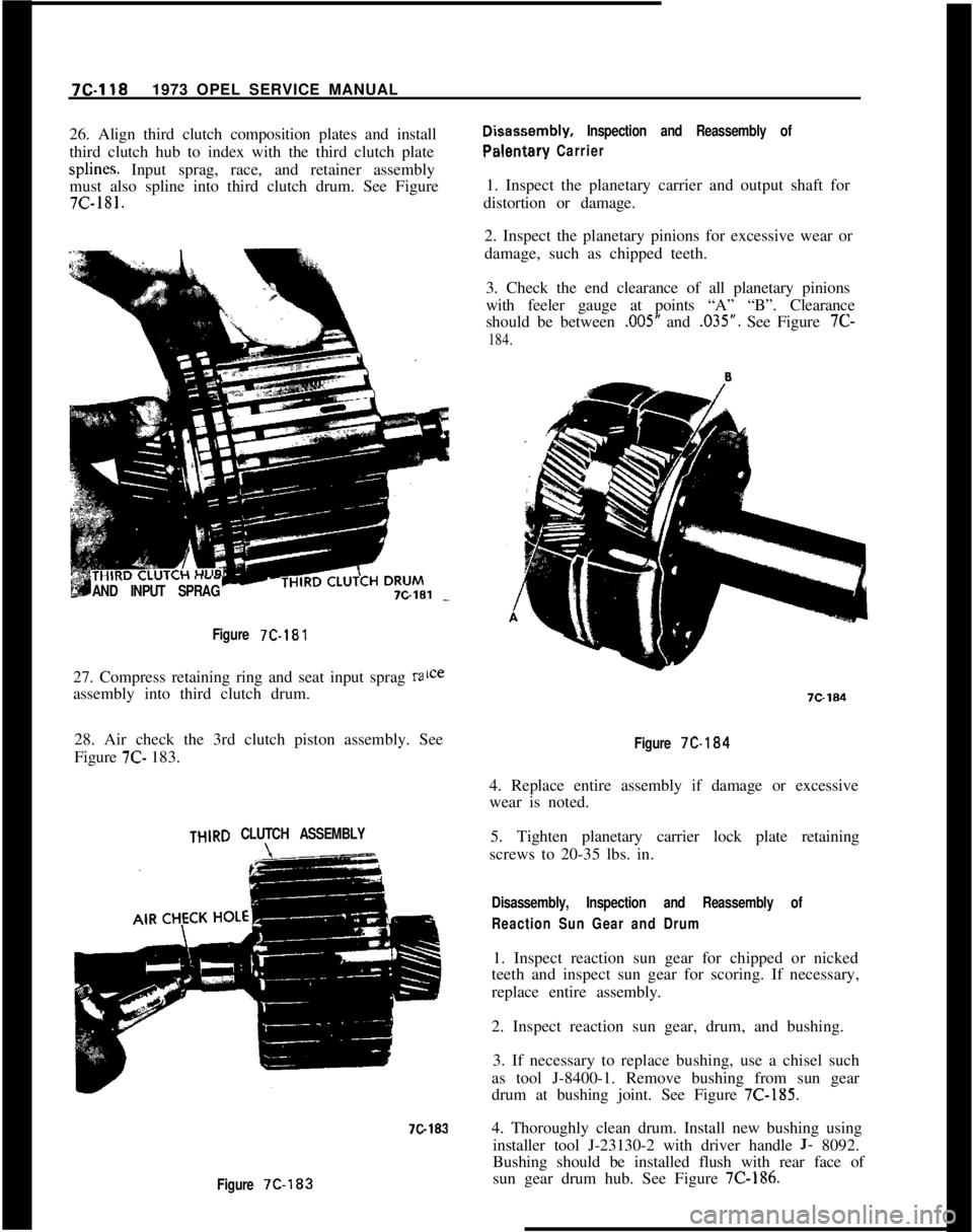
third clutch hub to index with the third clutch platesplines. Input sprag, race, and retainer assembly
must also spline into third clutch drum. See Figure7c-181...-I-AND INPUT SPRAG
Disaseembly, Inspection and Reassembly of
Palentary Carrier1. Inspect the planetary carrier and output shaft for
distortion or damage.
2. Inspect the planetary pinions for excessive wear or
damage, such as chipped teeth.
3. Check the end clearance of all planetary pinions
with feeler gauge at points “A” “B”. Clearance
should be between
,005” and .035”. See Figure 7C-
184.
Figure
7C-18127. Compress retaining ring and seat input sprag
raassembly into third clutch drum.
28. Air check the 3rd clutch piston assembly. See
Figure 7C- 183.
THlRD CLUTCH ASSEMBLY
7C183
Figure 7C-183
Figure 7C-184
4. Replace entire assembly if damage or excessive
wear is noted.
5. Tighten planetary carrier lock plate retaining
screws to 20-35 lbs. in.
Disassembly, Inspection and Reassembly of
Reaction Sun Gear and Drum1. Inspect reaction sun gear for chipped or nicked
teeth and inspect sun gear for scoring. If necessary,
replace entire assembly.
2. Inspect reaction sun gear, drum, and bushing.
3. If necessary to replace bushing, use a chisel such
as tool J-8400-1. Remove bushing from sun gear
drum at bushing joint. See Figure
7C-185.4. Thoroughly clean drum. Install new bushing using
installer tool J-23130-2 with driver handle
J- 8092.
Bushing should be installed flush with rear face of
sun gear drum hub. See Figure
7C-186.