ESP OPEL GT-R 1973 Workshop Manual
[x] Cancel search | Manufacturer: OPEL, Model Year: 1973, Model line: GT-R, Model: OPEL GT-R 1973Pages: 625, PDF Size: 17.22 MB
Page 552 of 625

REFRIGERANT COMPONENTS ALL MODELS9B- 43
4. Start the vacuum pump and slowly open low and
high pressure sides of manifold gauge set to avoid
forcing oil out of refrigeration system and pump,
Pressure is now being reduced on both sides of the
refrigeration system. If oil is blown from the vacuum
pump, it should be refilled to the proper level.
5. Observe low pressure gauge and operate vacuum
pump until gauge shows 28-29 inches vacuum. In all
evacuating procedures, specifications of 28-29 inchesof vacuum is used. This evacuation can only be at-
tained at or near sea level.
For each 1000 feet above sea level where this operat-ion is being-performed, the specification should be
lowered by one inch of mercury vacuum. At 5000
feet elevation, only 23 inches to 24 inches of vacuum
can normally be obtained.
If vacuum cannot be pulled to the minimum specifi-
cation for the respective altitude, it indicates a leak
in the system or gauge connections or a defective
vacuum pump. In this case, it will be necessary to
check for leaks as described under “Leak Testing
Refrigerant System”.
When specified vacuum level (28-29 inches at sea
level) is obtained, continue to run vacuum pump for
ten (10) ‘additional minutes. During these ten (10)
minutes:
A. Prepare for charging the system. If using a charg-
ing station, till charging cylinder. If using manifold
gauge set, make all preparations for charging system
as described under “Disposable Can Method” or
“Refrigerant Drum Method”.
B. Measure oil loss collected as a result of rapid
discharge.
C. Uncap compressor oil injector (J-24095) and open
valve. Flush J-24095 with refrigerant, close valve and
insert pick-up tube into graduated container of clean
refrigerant oil.
D. Con&ct J-24095 to suction fitting at the compres-
sor adapter fitting. When valve on J-24095 is opened,
the vacuum applied to the discharge side of the sys-
tem will suck oil into system from container. There-
fore,
close observation of oil level in the container is
necessary.E. Note level of oil in container. Open valve on
J-24095
u+il oil level in container is reduced by an
amount equal to that lost during discharge of system,
then shut valve. Take care not to add more oil than
was lost. ,,
F. Disconnect J-24095 and attach pick-up tube fit-
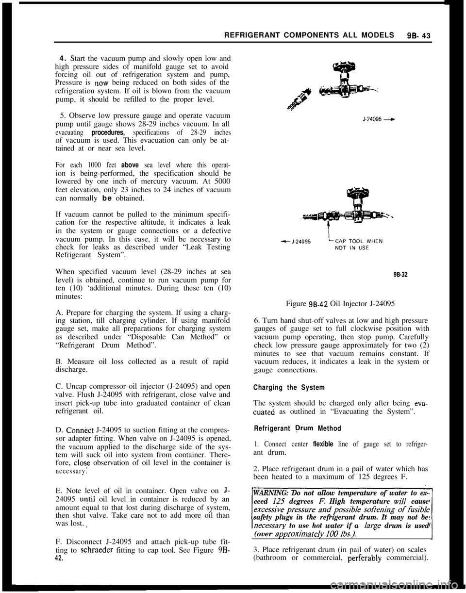
ting to schraeder fitting to cap tool. See Figure 9B-
42.J-24095
-98.32
Figure 98.42 Oil Injector J-24095
6. Turn hand shut-off valves at low and high pressure
gauges of gauge set to full clockwise position with
vacuum pump operating, then stop pump. Carefully
check low pressure gauge approximately for two (2)
minutes to see that vacuum remains constant. If
vacuum reduces, it indicates a leak in the system or
gauge connections.
Charging the SystemThe system should be charged only after being eva-cuated as outlined in “Evacuating the System”.
Refrigerant orurn Method
1. Connect center flexible line of gauge set to refriger-ant drum.
2. Place refrigerant drum in a pail of water which has
been heated to a maximum of 125 degrees F.
WARNING: Do not allow temperature of water to ex-
ceed I25
degrees E High temperature will cause
safety plugs in the refrigerant drum. It may not be
necessarv to use hot water if a /arae drum is used(over
ap)roximateIy 100 lbs.).-I3. Place refrigerant drum (in pail of water) on scales
(bathroom or commercial, perferably commercial).
Page 580 of 625

REI:RIGERANT COMPONENTS ALL MODELS9s. 71
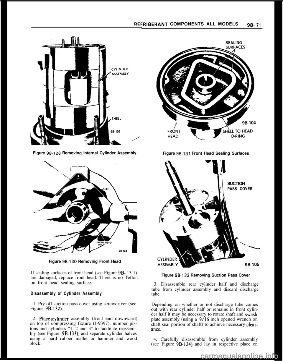
/Figure 9%128 Removing Internal Cylinder Assembly
Figure 9B-130 Removing Front Head
If sealing surfaces of front head (see Figure 9B- 13 1)
are damaged, replace front head. There is no Teflon
on front head sealing surface.
Disassembly of Cylinder Assembly1. Pry off suction pass cover using screwdriver (see
Figure
9B-132).2. Placevzylinder assembly (front end downward)
on top of compressing fixture (J-9397), number pis-
tons and cylinders “1, 2 and 3” to facilitate reassem-
bly (see Figure
9B-133), and separate cylinder halves
using a hard rubber mallet or hammer and wood
block.
SEALINGFigure 96.131 Front Head Sealing Surfaces
SUCTION
PASS COVERFigure 98-132 Removing Suction Pass Cover
3. Disassemble rear cylinder half and discharge
tube from cylinder assembly and discard discharge
tube.Depending on whether or not discharge tube comes
out with rear cylinder half or remains in front cylin-
der half it may be necessary to rotate shaft and wash
plate assembly (using a 9/16 inch opened wrench on
shaft seal portion of shaft) to achieve necessary clear-kl”Ct?.
4. Carefully disassemble from cylinder assembly
(see Figure 9B-134) and lay in respective place on
Page 583 of 625

98.74 1973 OPEL SERVICE MANUAL
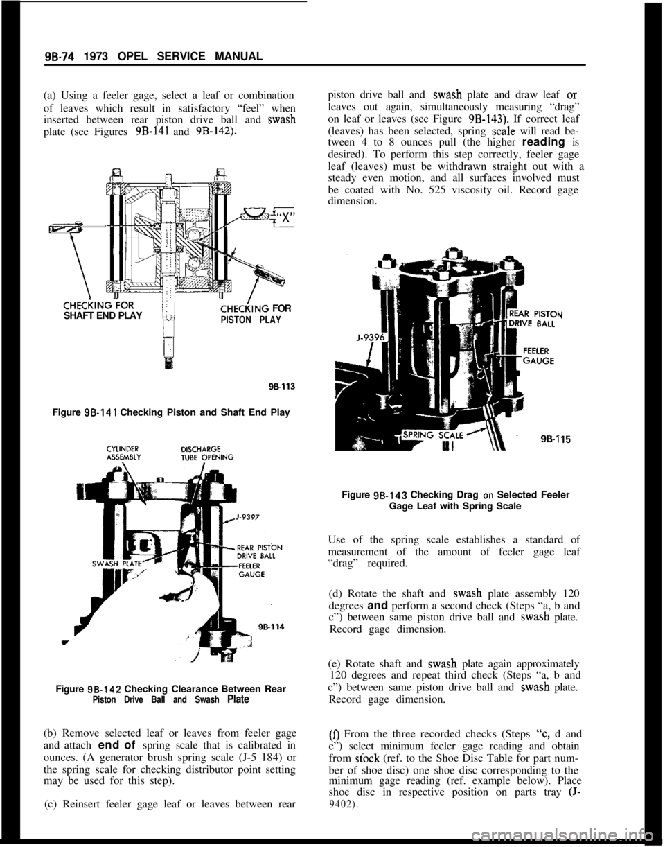
(a) Using a feeler gage, select a leaf or combination
of leaves which result in satisfactory “feel” when
inserted between rear piston drive ball and wash
plate (see Figures 9B-141 and 9B-142).CHECi(lNG?OR
SHAFT END PLAY
CHE&NG FOR
PISTON PLAY
98113Figure 98-141 Checking Piston and Shaft End Play
Figure 98-142 Checking Clearance Between Rear
Piston Drive Ball and Swash Plate(b) Remove selected leaf or leaves from feeler gage
and attach end of spring scale that is calibrated in
ounces. (A generator brush spring scale (J-5 184) or
the spring scale for checking distributor point setting
may be used for this step).
(c) Reinsert feeler gage leaf or leaves between rearpiston drive ball and wash plate and draw leaf or
leaves out again, simultaneously measuring “drag”
on leaf or leaves (see Figure
9B-143). If correct leaf
(leaves) has been selected, spring
:scale will read be-
tween 4 to 8 ounces pull (the higher reading is
desired). To perform this step correctly, feeler gage
leaf (leaves) must be withdrawn straight out with a
steady even motion, and all surfaces involved must
be coated with No. 525 viscosity oil. Record gage
dimension.
Y
i15Figure 98.143 Checking Drag
on Selected Feeler
Gage Leaf with Spring Scale
Use of the spring scale establishes a standard of
measurement of the amount of feeler gage leaf
“drag” required.
(d) Rotate the shaft and wash plate assembly 120
degrees and perform a second check (Steps “a, b and
c”) between same piston drive ball and wash plate.
Record gage dimension.
(e) Rotate shaft and wash plate again approximately
120 degrees and repeat third check (Steps “a, b and
c”) between same piston drive ball and wash plate.
Record gage dimension.(0 From the three recorded checks (Steps
“c, d and
e”) select minimum feeler gage reading and obtain
from
stock (ref. to the Shoe Disc Table for part num-
ber of shoe disc) one shoe disc corresponding to the
minimum gage reading (ref. example below). Place
shoe disc in respective position on parts tray
(J-
9402).
Page 585 of 625

9B-76 1973 OPEL SERVICE MANUAL
race. If, for example a feeler gage reading of 0.009
inch results, a thrust race with a number “9”,
stamped on it should be selected.Thrust Race TableSERVICEID NO.THICK-
PART NO. ON RACE
NESS
6556000
0.0920
6556050
5.09656556055
5l/2.09706556060
6.0975
65560656
l/2.09806556070
7.0985
6556075
7l/2.09906556080
8.0995
6556085
8l/2.lOOO6556090
T/2,100s
65560959.lOlO
655610010,101s
655610510 l/2.10206556110
.10256556115
11111/2.10306556120
12.1035The selected thrust race will replace only the “zero”
outer rear thrust race. The remaining three “zero”
thrust races will remain as part of the cylinder assem-
bly.
13. Remove cylinder assembly from inside compress-
ing fixture (J-9397), place on top of compressing
fixture (see Figure 9B-133) and disassemble rear cyl-
inder from front cylinder using rubber mallet or
hammer and wood block.
14. Carefully disassemble one piston at a time from
front cylinder and lay piston, front and rear piston
drive balls and front “zero” shoe disc in respective
slot of parts tray (J-9402). To disassemble, rotatewash plate until piston is at highest point, raise awash plate approximately
l/2 inch and lift out pis-
ton and related parts, one at a time.
15. Remove outer rear ‘?ero” thrust race from shaft
and set it aside for future gaging procedures.
16. Remove previously selected outer rear thrust
race from parts tray, lightly coat with clear pe-
troleum jelly and assemble onto shaft.
Final Reassembly of Cylinder Assembly1. Reassemble piston rings (if service pistons) onto
pistons (ring scraper groove toward center of piston)
and rotate ring so that break or gap in ring can be
squeezed together when piston is being inserted into
cylinder bore.
2. Reassemble piston drive balls, “zero” and se-lected shoe discs onto No. “1” piston, and apply
clear petroleum jelly to piston pockets and shoe discs
so that balls and discs stick to piston. BE SURE to
reassemble balls and shoe discs into their specific
positions on front and rear of piston.
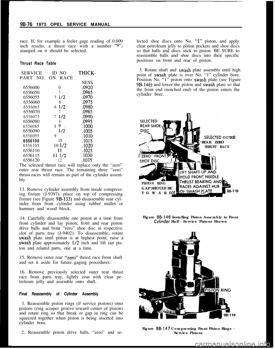
3. Rotate shaft and wash plate assembly until high
point of wash plate is over No. “1” cylinder bore.
Position No. “1” piston onto wash plate (see Figure9B-146) and lower the piston and wash plate so that
the front end (notched end) of the piston enters the
cylinder bore.XTED OUTER
/REAR ZERO
THRUST RACE
PISTON RINGGAP SHOULD BE
TOWARD
98-118Figure 98.146 Installing Piston Assembly in Front
Cvlinder Half - Service Pistons Shown
Figure 98.147 Compressing Front Piston Rings
-Service Pistons