check oil OPEL GT-R 1973 Workshop Manual
[x] Cancel search | Manufacturer: OPEL, Model Year: 1973, Model line: GT-R, Model: OPEL GT-R 1973Pages: 625, PDF Size: 17.22 MB
Page 324 of 625
COOLING SYSTEM6B- 33
remove drain plug on right.side of cylinder block. Set
heater temperature control valve at full heat posi-
tion. After the cooling system is drained, and plugs
reinstalled, fill the system with clean water. Run the
engine long enough to open the thermostat for com-
plete circulation through the system, then com-
pletely drain the cooling system before sediment has
a chance to settle.
Conditioning the Cooling System
“Rust Inhibitor and Stop Leak”, or equivalent listed
under Group 8.800 is recommended for use in the
cooling system, particularly when preparing for in-
stallation of anti-freeze solution. This material stops
small seepage leaks, has rust preventive properties
and its soluble oil is effective in eliminating a squeal-
ing noise which sometimes develops at the water
pump seal washer. Instructions for its application are
printed on the conditioner bottle.
It is very important to make certain that the cooling
system is properly prepared before an anti-freeze so-
lution is installed, otherwise loss of solution through
leakage may occur or seepage may result in damage
to the engine. The cooling system should be drained
and flushed as described under Draining and Flush-
ing Cooling System. All joints should be checked for
leakage and corrected, and the conditioner described
above should be added with the anti-freeze solution.
Inspect the water pump, radiator core, heater and
defroster cores, water jacket plugs, and edge of cylin-
der head gaskets for evidence of water leaks. Tighten
all hose clamps in the cooling and heating systems
and replace any deteriorated hoses.
Using and Testing Anti-Freeze
Solutions
Inhibited year around (ethylene glycol type) engine
coolant solution which is formulated to withstand
two full calendar years of normal operation without
draining or adding inhibitors should be used at all
times. Freeze protection should be provided to pro-
tect against corrosion. When adding solution due to
loss of coolant for any reason or in areas where tem-
peratures lower than minus 20 degrees F. may be
encountered, a sufficient amount of any of the sev-
eral brands of year around coolant (Ethylene Glycol
base) compatible to GM Specification 1899-M avail-
able on the market should be used. Water or alcohol
base coolants are not recommended for this vehicle
at any time.
If for any reason water only is used as a coolant in
an emergency, it is extremely important that Buick
Heavy Duty Cooling System Protector and Water
Pump Lubricant or equivalent be added to the cool-
ing system as soon as possible. If any other cooling
System protector is used, be certain it is labeled toindicate that it meets General Motors Specification
GM 1894-M. It should be recognized that this is only
a temporary measure. The manufacture intends that
permanent type coolant solution be used year around
in the cooling system.
The cooling system should be completely drained
and the recommended coolant installed every two (2)years.It is advisable to test the anti-freeze solution at inter-
vals during the winter to make certain that the solu-
tion has not been weakened. Use only hydrometers
which are calibrated to read both the specific gravity
and the temperature, and have a table or other means
of converting the freezing point at various tempera-
tures of solution. Disregarding the temperature of
the solution when making the test may cause an error
as large as 30 degrees F. Care must be exercised to
use the correct float or table for the particular type
of anti-freeze being tested.
Fan Belt Adjustment or Replacement
A tight fan belt will cause rapid wear of the alterna-
tor and water pump bearings. A loose belt will slip
and wear excessively and will cause noise, engine
over-heating, and unsteady alternator output. A fan
belt which is cracked or frayed, or which is worn so
that it bottoms in the pulleys should be replaced. The
fan belt may be replaced by loosening the alternator
brace at alternator, slightly loosening the alternator
mounting bolts and moving alternator inward to pro-
vide maximum slack in the belt.
The alternator must be moved outward to adjust the
fan belt. After the generator brace and mounting
bolts are securely tightened, the fan belt tension
should be 45 lb. using Tensioner J-23600.
WARNING: Zfa
fan blade is bent or damaged in any
way, no attempt should be made to repair and reuse
the damaged part. A bent or damaged fan assembly
should always be replaced with a new
fal. assembly.
It is essential that fan assemblies remain in proper
balance and proper balance cannot be assured once
a fan assembly has been bent or damaged. A fan
assembly that is not in proper balance could fail and
fly apart during subsequent
we creating an ex-
tremely dangerous condition.
Radiator Thermostat Inspection and Test
A sticking radiator thermostat will prevent the cool-
ing system from functioning properly. If the thermo-
stat sticks in the open position, the engine will warm
up very slowly. If the thermostat sticks in the closed
position, the engine will overheat.
The thermostat may be removed for inspection and
Page 325 of 625
6B- 341973 OPEL SERVICE MANUAL
test by partially draining the cooling system and dis-
connecting the water outlet housing from the ther-
mostat housing which is mounted on the right front
side of cylinder head.
The standard thermostat valve should start to open
at 189 degrees F and fully open at approximately 212
degrees F. If thermostat does not operate at specified
temperatures, it should be replaced as it cannot be
repaired.MAJOR REPAIR
WATER PUMP REPAIRSThe water pump bearing outer race is shrunk fit into
the water pump cover. For this reason the cover,
shaft bearing, and hub are not repairable.
Water Pump RemovalOpel radiators do not have a drain plug. Drain radia-
tor by first, loosening radiator cap, then remove
lower hose from lower radiator tank.
1. Drain coolant into a clean container. Remove
radiator and shroud.
2. Remove fan belt.
3. Remove fan blade and pulley on water pump shaft.
4. Disconnect inlet hose and heater hose from water
pump. Remove bolts, pump assembly and gasket
from timing chain cover.
5. Check pump shaft bearing for end play or rough-
ness in operation. If bearings are not in serviceable
condition, the assembly must be replaced.
Water Pump Installation1. Make sure the gasket surfaces on pump and timing
chain covers are clean. Install pump assembly with
new gasket. Bolts must be tightened uniformly.
Torque to 11 lb. ft.
2. Install radiator and shroud. Connect radiator hose
to pump inlet and heater hose to nipple.
3. Install fan pulley and fan blade, tighten attaching
bolts securely. Install belts and adjust for proper
tension.4. Fill cooling system and check
,for leaks at pump
and hose joints.
RADIATOR REMOVAL AND INSTALLATION
RemovalI. Loosen radiator cap, then remove lower radiator
hose and drain radiator coolant into suitable con-
tainer.
2. On vehicles with automatic transmission, unscrew
oil lines from connectors on lower radiator tank and
plug lines. On GT models with automatic transmis-
sion the lines have to be disconnected at the coupling
before removing from the tank. It is essential that no
dirt enters the oil lines. When unscrewing oil lines,
hold connectors on lower radiator tank with pliers to
avoid leakages. Ensure that no dirt enters oil cooler.
3. Remove lower attaching nut and slide radiator
upward and out of engine compartment.
Installation1. Install radiat,or into engine compartment and se-
cure lower attaching nut.
2. On vehicles with automatic transmissions, fasten
oil cooler lines to lower radiator tank. It is essential
that no dirt enters the oil lines. When tightening oil
lines, hold connectors on lower radiator tank with
pliers to avoid leakages. Ensure that no dirt enters oil
cooler. Torque to 1 I-15
lbs.ft.3. Install lower radiator hose and add collected coo-
lant.
All Opels are provided with a radiator initial fill of
an antifreeze solution containing corrosion inhibitor.
The antifreeze has either a glycol or glycerin base
and protects the engine against freezing, down to
minus 22 degrees F. (minus 30 degrees C.). Before
the start of the cold season, coolant must be checked
with a hydrometer and if necessary, brought to the
necessary specific gravity by adding anti-freeze with
a glycol or glycerin base. As the specific gravities of
all anti- freeze solutions having a glycol or glycerin
base are practically the same, the hydrometer can be
used for all these types. Because of the tolerances of
the hydrometer, or slight differences in specific
gravity, variations of plus or minus 5 degrees can be
expected. Coolant must be checked at a temperature
of plus 68 degrees F. (plus 20 degrees C.)
Page 329 of 625
6C- 381973 OPEL SERVICE MANUALCAUTION:Because the fuel pump is below fuel tank
level, fuel
will drain from the tank. when the supply
hne is disconnected from the fuel pump.1. Pull fuel supply line and rubber connector from
fuel pump. Plug rubber connector to prevent fuel
loss.2. Remove fuel pump cap, gasket and plastic
strainer.
3. Cover center opening in sediment bowl with finger
and blow out sediment bowl with compressed air.
4. Wash plastic strainer in solvent; if strainer does
not clean-up or is damaged, replace strainer.
5. Install clean parts, noting the following:
(a) Strainer must be properly seated with projections
facing upward.(b) A new cap gasket must be positioned over
strainer.
(c) Sealing ring must be in place on cap retaining
screw.6. Reconnect fuel supply line. Start engine and check
for leaks.
EVAPORATION CONTROL SYSTEMProper performance of the system requires the use of
a non-vented fuel tank cap, hose connections be leak-
free, and all hoses routed correctly to avoid a
pinched or blocked line.
Maintenance requirements demand only that the ac-
cumulator purge air tilter, an oiled foam filter assem-
bled in the bottom of the canister, be replaced at
12,CKO mile intervals. Under extremely dusty condi-
tions, more frequent attention may be required.
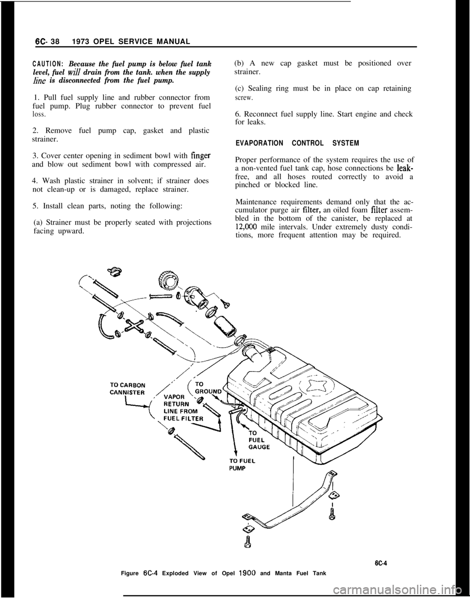
Figure
W-4 Exploded View of Opel 1900 and Manta Fuel Tank
Page 356 of 625
TUNE-UP
ALL MODELS
CONTENTS
Subject
DESCRIPTION AND OPERATION:
Purpose of a Tune-Up. . . . . . . . . . . . . . . . . . . . . . . . . . . . . . . . . . . . . . . . . . . . . . . . . , . . . .DIAGNOSIS: (Not Applicable)
MAINTENANCE AND ADJUSTMENTS:
EngineTune-UpMechanicalOperations. . . . . . . . . . . . . . . . . . . .
EngineTune-UpInstrumentChecks. . . . . . . . . . . . . . . . . . . . . . . . . . . .MAJOR REPAIR: (Not Applicable)
SPECIFICATIONS:
Tune-Uo Soecifications and Adjustments
. . . . . . . . . . . . . . . .Page No.6G-65
6G-6566-6766-68
DESCRIPTION AND OPERATION
PURPOSE OF TUNE-UP
The purpose of an engine tune-up is to restore powerand performance that may have been lost through,
loss of adjustment, wear, corrosion, or deterioration
of one or more parts or units. In the normal operat-
ion of an engine, these changes take place gradually
at quite a number of points so that it is seldom advis-able to attempt an improvement in performance by
correcting one or two items only. Time will be savedand more lasting results will be assured by following
a definite and thorough procedure of analysis and
correction of all items affecting power and perform-
ance. Because of Federal laws, limiting exhaust emis-sions, it is even more important that the engines
tune-up is done accurately, using the specifications
listed and the tune-up sticker found in each engine
compartment.
Economical, trouble free operation can better be as-sured if a complete tune-up is performed at first 4
months or
6,ooO miles of operation - then at 12
month or 12,000 mile intervals.
The parts or units which affect power and perform-
ance may be divided, into three groups (1) compres-sion, (2) ignition and (3) carburetion. The tune-up
procedure should cover these groups in the order
given. While the items affecting compression and
ignition may be handled according to individual
preference, correction of items in the carburetiongroup should not be attemplcu
ulllll all items in
compression and ignition have been satisfactorily
corrected.
MAINTENANCE AND ADJUSTMENTS
ENGINE TUNE-UP OPERATIONS
CompressionTo make sure hydrocarbon and carbon monoxide
emissions will be within limits, it is very important
that the adjustments be followed exactly.
The suggested procedure for engine tune-up is as
follows:1. Remove all spark plugs.
2. Position throttle and choke valve in full open posi-tion.
3. Connect jumper wire between distributor terminalof coil and ground on engine to avoid high tension
sparking while cranking engine.
4. Hook up starter remote control cable and turn
ignition switch to “on” position.
5. Firmly insert compression gage in spark plug port.Crank engine to obtain highest possible reading.
Page 357 of 625
6G- 661973 OPEL SERVICE MANUAL
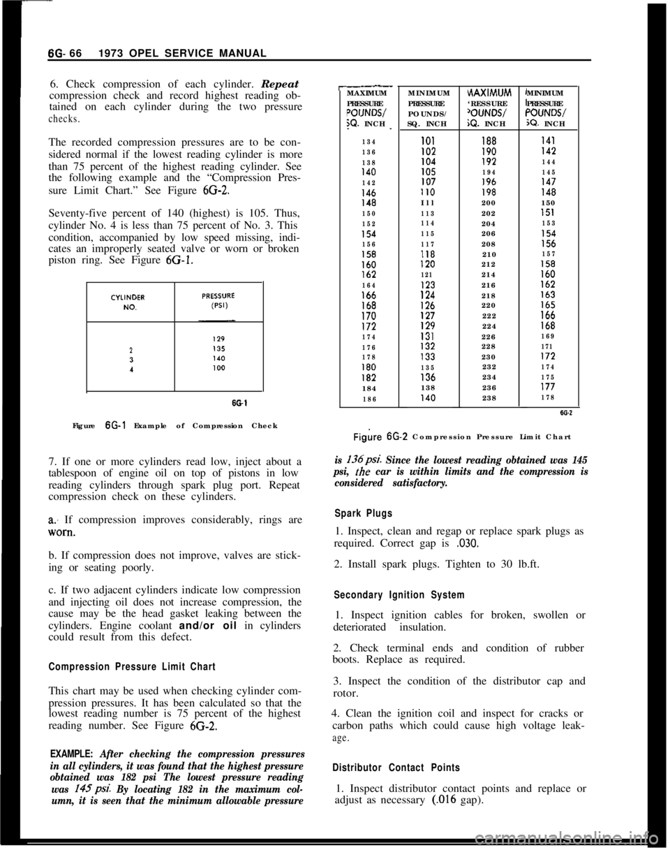
6. Check compression of each cylinder. Repeat
compression check and record highest reading ob-
tained on each cylinder during the two pressurechecks.The recorded compression pressures are to be con-
sidered normal if the lowest reading cylinder is more
than 75 percent of the highest reading cylinder. See
the following example and the “Compression Pres-
sure Limit Chart.” See Figure
6G-2.Seventy-five percent of 140 (highest) is 105. Thus,
cylinder No. 4 is less than 75 percent of No. 3. This
condition, accompanied by low speed missing, indi-
cates an improperly seated valve or worn or broken
piston ring. See Figure 6G-1.
23
I
SO-1Figure 6G-1 Example of Compression Check
7. If one or more cylinders read low, inject about a
tablespoon of engine oil on top of pistons in low
reading cylinders through spark plug port. Repeat
compression check on these cylinders.
a: If compression improves considerably, rings are
lV0*tl.b. If compression does not improve, valves are stick-
ing or seating poorly.
c. If two adjacent cylinders indicate low compression
and injecting oil does not increase compression, the
cause may be the head gasket leaking between the
cylinders. Engine coolant and/or oil in cylinders
could result from this defect.
Compression Pressure Limit ChartThis chart may be used when checking cylinder com-
pression pressures. It has been calculated so that the
lowest reading number is 75 percent of the highest
reading number. See Figure 6G-2.
EXAMPLE: After checking the compression pressures
in all cylinders, it was found that the highest pressure
obtained was 182 psi The lowest pressure reading
was 145psi.
By locating 182 in the maximum col-
umn, it is seen that the minimum allowable pressure
r-.__MAXIMUM
PRESSURE
POIJNWW. INCH
--
134
136
138
140
142
146148
150
152
154
156
158160lb2
164166168170172
174
176
178
180182184
186MINIMUM
PRESSURE
POUNDS/
SQ. INCHHAXIMUM
‘RESSURE
‘OUNWiQ. INCHMINIMUM
PRESSURE“OUNWX?. INCH
101188I41I02190142104192144105194145107196147II0198148Ill200150
113202151
114204153
115206154
117208156118210157120212158
121214160123216162
124218163
126220165127222166129224168131226169132228171133230172
135232174136234175138236177140238178
Figire 6G.2 Compression Pressure Limit Chart
is 136psi. Since the lowest reading obtained was 145
psi,
the car is within limits and the compression is
considered satisfactory.
Spark Plugs1. Inspect, clean and regap or replace spark plugs as
required. Correct gap is
,030.2. Install spark plugs. Tighten to 30 lb.ft.
Secondary Ignition System1. Inspect ignition cables for broken, swollen or
deteriorated insulation.
2. Check terminal ends and condition of rubber
boots. Replace as required.
3. Inspect the condition of the distributor cap and
rotor.
4. Clean the ignition coil and inspect for cracks or
carbon paths which could cause high voltage leak-
age.
Distributor Contact Points1. Inspect distributor contact points and replace or
adjust as necessary
(.016 gap).
Page 358 of 625
2. If inspection of contact points indicates excessive
burning, pitting or wear, check condenser and re-
place if necessary.
3. Inspect all connections and wires in the primary
ignition circuit. Correct any abnormal conditions
found.Carburetor1. Clean fuel strainer in fuel pump. To prevent fuel
leakage in pump, disconnect “IN” line from pump
and raise end above fuel level. The in-line fuel filter
should be replaced every 12,000 miles or every 12
months.
2. Check for freedom of choke valve operation and
clean shaft if necessary, with suitable solvent.
3. Inspect throttle cable or linkage bracket and re-
turn spring for wear. With helper depressing acceler-
ator pedal to floor, check for wide open throttle.
Adjust accelerator pedal height so wide open throttle
is obtained when pedal is within
l/2 inch from floor.
Lubricate linkage pivot points with engine oil.
Air CleanerCheck paper element every 6,000 miles and replace
every
24,ooO miles. If a vehicle is operated in dusty
territory, check condition of air cleaner element
more frequently and replace if necessary.
Fan Belt1. Inspect belt for wear, cracks or frayed points.
Replace and/or adjust as necessary. Specified ten-
sion for belt using Gauge J-23600 is 45 lbs.
Cooling System1. Inspect the radiator, water pump, cylinder head
areas and all radiator and heater hose connections
for evidence of engine coolant leaks.
2. Inspect all hoses for deterioration from gas and oil
contact. Correct as required.
Inspection should be made with engine operating at
normal temperature, cooling system completely
filled, temperature control lever fully open and nor-
mal pressure in the system. Normal pressure should
be 13.2 to 15.2 psi.
Engine Lubrication SystemInspect engine for evidence of oil leakage. Correctany abnormal condition with sealastic or new seals
and gaskets.
Battery
1. Inspect battery, battery mount and cables and
check electrolyte level. Proper level should be just
above the cell plates.
CAUTION:Do not over fill.
2. Determine the serviceability of the battery by ap-
plying the 421 Battery Test.
Positive Crankcase VentilationClean crankcase ventilator metered orifice in the in-
take manifold fitting every 6,000 miles. Also all hoses
and fittings should be inspected, cleaned and re-
placed, if necessary.
To clean, remove rubber hose from metered orifice
and apply air pressure to orifice to remove any for-
eign particles that may be trapped.
Valve Lifter AdjustmentRefer to Engine Mechanical and Mounts section for
valve lifter adjustment procedure.
Engine Tune-Up Instrument ChecksThe following instrument checks and adjustments
serve as a final check on engine condition. These
checks may discover some new problems that may
not have been obvious before. The engine is also
given its final adjustments that will assure maximum
performance, reliability, and proper emission con-
trol.
Refer to Electrical Group for checking procedures of
the following:
Cranking Voltage Check
Ignition Timing
Distributor Advance
Ignition Output
Secondary Resistance
Current Output and Voltage Setting
Idle Speed and Mixture AdjustmentsRefer to carburetor section.
Page 363 of 625
7A- 21973 OPEL SERVICE MANUALDIAGNOSIS
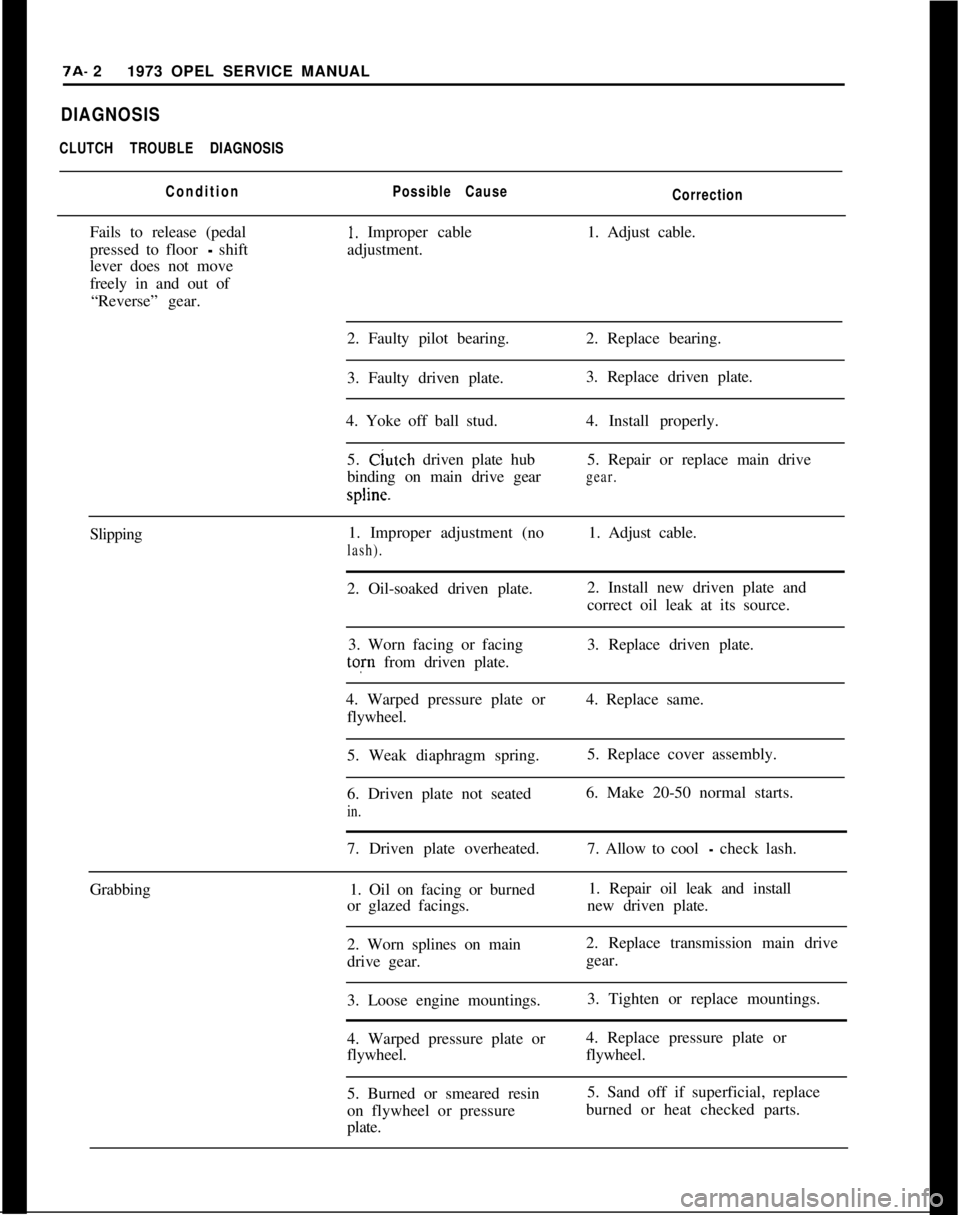
CLUTCH TROUBLE DIAGNOSIS
ConditionPossible Cause
CorrectionFails to release (pedal
1. Improper cable1. Adjust cable.
pressed to floor
- shiftadjustment.
lever does not move
freely in and out of
“Reverse” gear.
2. Faulty pilot bearing.2. Replace bearing.
3. Faulty driven plate.3. Replace driven plate.
4. Yoke off ball stud.4. Install properly.
5. Clutch driven plate hub5. Repair or replace main drive
binding on main drive gear
gear.spline.
Slipping1. Improper adjustment (no1. Adjust cable.
lash).2. Oil-soaked driven plate.2. Install new driven plate and
correct oil leak at its source.
3. Worn facing or facing3. Replace driven plate.tofn from driven plate.
4. Warped pressure plate or4. Replace same.
flywheel.
5. Weak diaphragm spring.5. Replace cover assembly.
6. Driven plate not seated6. Make 20-50 normal starts.
in.7. Driven plate overheated.7. Allow to cool
- check lash.
Grabbing1. Oil on facing or burned1. Repair oil leak and install
or glazed facings.new driven plate.
2. Worn splines on main2. Replace transmission main drive
drive gear.gear.
3. Loose engine mountings.3. Tighten or replace mountings.
4. Warped pressure plate or4. Replace pressure plate or
flywheel.flywheel.
5. Burned or smeared resin5. Sand off if superficial, replace
on flywheel or pressureburned or heat checked parts.
plate.
Page 364 of 625
CLUTCH7A- 3Possible CauseCorrectionRattling
- Transmission
Click1. Yoke loose on ball stud
in bearing groove.1. Check ball stud and retaining
spring and replace if necessary.
2. Oil in driven plate
damper.2. Replace driven plate.
3. Driven plate damper
spring failure.3. Replace driven plate,
Throw-out bearing noise
with clutch fully
engaged.1. Improper adjustment.1. Adjust cable.
2. Throw-out bearing bind-
ing on transmission bearing
retainer.2. Clean, relubricate, check for
burrs, nicks, etc.3.
InsuffIcient tension
between yoke and ball stud.3. Replace yoke.
4. Yoke improperly
installed.4. Install properly.
5. Weak linkage return
spring.5. Replace spring.
Noisy1. Worn throw-out bearing.1. Replace bearing.
2. Fork off ball stud
(heavy clicking).2. Install properly.
Pedal stays on floor
when disengaged.1. Bind in cable.1. Lubricate and free up cable.
2. Spring weak in pressure
plate.2. Replace
3. Weak linkage return
spring.3. Replace
High Pedal Effort1. Bind in cable.
2. Driven plate worn.1. Lubricate and free up cable.
2. Replace driven plate.
Clutch facings worn near
rivets.1. Normal wear.1. Replace driven plate assembly
only, and readjust clutch pedal and
cable.
Pressure plate assembly
friction surface badly
scored or rough.1. Improper clutch pedal
lash causing pressure plate
to come in contact with
rivets.1. If roughness can be smoothed with
fine emery cloth, do not replace
pressure plate assembly; if it cannot,
replace the pressure plate and driven
plate assembly. Adjust clutch.
Page 367 of 625
7A- 61973 OPEL SERVICE MANUAL1. FIywheeI and Pressure PlateExamine friction surfaces of flywheel and pressure
plate for scoring or roughness. Slight roughness may
be smoothed with fine emery cloth, but if surface is
deeply scored or grooved the part should be re-
placed.
2.
CJutch Driven Plate
Inspect driven plate for condition of facings, loose
rivets, broken or very loose torsional springs.
If facings are worn down near rivets or are oily, the
plate assembly should be replaced. A very slight
amount of oil on clutch facings will cause clutch grab
and chatter. A large amount of oil on facings will
cause slippage. Removal of oil by solvents or by buff-
ing is not practical since oil will continue to bleed
from facing material when hot.
When oil is found on driven plate facings, examine
transmission drainback hole, pilot bushing, engine
rear main bearing and other points of possible oil
leakage.
Test the fit of driven plate hub on transmission main
drive gear for an easy sliding fit.
Regardless of whether the old plate or a new one is
to be installed, the plate should be checked for run-
out. Lateral run-out measured at disc circumference
should not exceed
.016 inch.
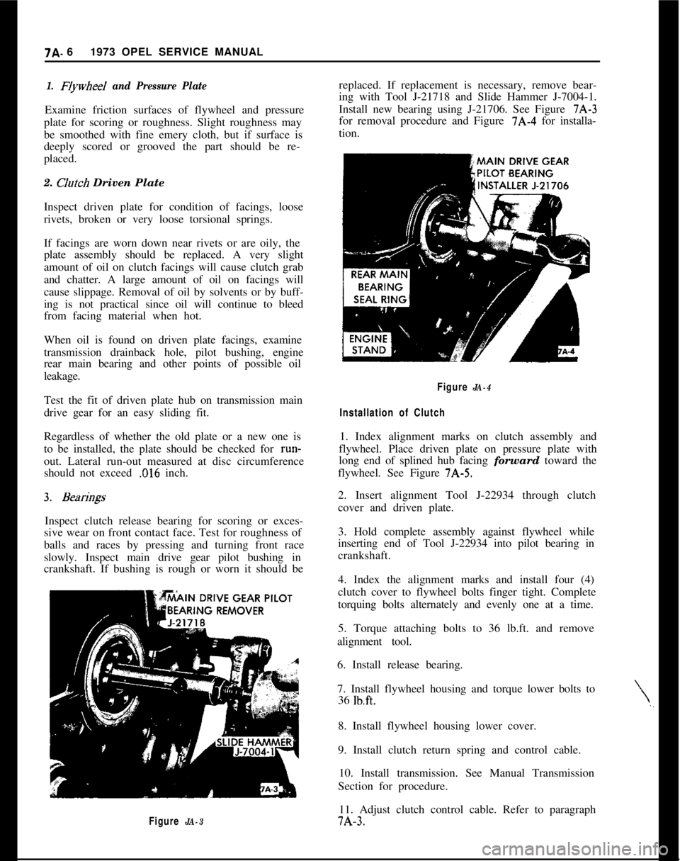
Inspect clutch release bearing for scoring or exces-
sive wear on front contact face. Test for roughness of
balls and races by pressing and turning front race
slowly. Inspect main drive gear pilot bushing in
crankshaft. If bushing is rough or worn it should be
Figure JA-3replaced. If replacement is necessary, remove bear-
ing with Tool J-21718 and Slide Hammer J-7004-1.
Install new bearing using J-21706. See Figure 7A-3
for removal procedure and Figure 7A-4 for installa-
tion.
\,,
Figure JA-4
Installation of Clutch1. Index alignment marks on clutch assembly and
flywheel. Place driven plate on pressure plate with
long end of splined hub facing forward toward the
flywheel. See Figure 7A-5.
2. Insert alignment Tool J-22934 through clutch
cover and driven plate.
3. Hold complete assembly against flywheel while
inserting end of Tool J-22934 into pilot bearing in
crankshaft.
4. Index the alignment marks and install four (4)
clutch cover to flywheel bolts finger tight. Complete
torquing bolts alternately and evenly one at a time.
5. Torque attaching bolts to 36 lb.ft. and remove
alignment tool.
6. Install release bearing.
7. Install flywheel housing and torque lower bolts to
36
lb.ft.8. Install flywheel housing lower cover.
9. Install clutch return spring and control cable.
10. Install transmission. See Manual Transmission
Section for procedure.
11. Adjust clutch control cable. Refer to paragraph7A-3.
Page 397 of 625

7C- 361973 OPEL SERVICE MANUAL
CONTENTS
Subject
DESCRIPTION AND OPERATION:
Description of the Opel Three-Speed Automatic,Transmission....................................................................
Principles of Operation....................................................
ComponentOperation
andLocation............................
Mechanical Operation......................................................
Hydraulic Control Units and Valves............................H,y&aulic Operation..........................................................
DIAGNOSIS:
Sequence for Trouble Diagnosis..................................
Checking
Procedures........................................................
ExternalOil
Leaks..............................................................
Trouble
DiagnosisChart..................................................
Hydraulic Pressure
Checks............................................
MAINTENANCE AND ADJUSTMENTS:
Detent Cable Adjustment..............................................
ServicingSelector
Lever..................................................
MAJOR REPAIR:
Transmission Removal and Installation
AllModels........................................................................
Removalof
OilPan............................................................
RemovalofValveBody....................................................
Removalof
ServoPiston................................................
Removalof
Selector
LeverandShaft........................
RemovalofModulatorAssembly..................................
RemovalofDetentValveAssembly............................
RemovalofExtensionHousing......................................
Removal of Speedometer Drive Gear, Governor
Body and Governor Hub..............................................
Removal of Converter Housing, Oil Pump, Reverse
and Second Clutch Assembly..................................
Removal of Third Clutch Assembly, Planetary
Carrier Assembly, Reaction Sun Gear and Drum
Assembly and Low Bank............................................
Disassembly, Inspection and Reassembly of
Converter Housing, Oil Pump and Reverse Clutch
Disassembly, Inspection and Reassembly of
SecondClutch
................................................................
Disassembly, Inspection and Reassembly of
ThirdClutch....................................................................
Disassembly, Inspection and Reassembly of
Planetary Carrier
............................................................Page No.7c- 377c- 387c- 447c- 487c- 487c- 64
7C- 81
7C- 81IC- 817c- 827c- 877c- 917c- 937c- 947c- 99.7c- 99
7c-1007c-loo
7&l 01
7c-102
7c-102
7c-103
7c-103
7c-104
7c-105
7c-111
7c-114
7c-118