light OPEL GT-R 1973 Workshop Manual
[x] Cancel search | Manufacturer: OPEL, Model Year: 1973, Model line: GT-R, Model: OPEL GT-R 1973Pages: 625, PDF Size: 17.22 MB
Page 148 of 625

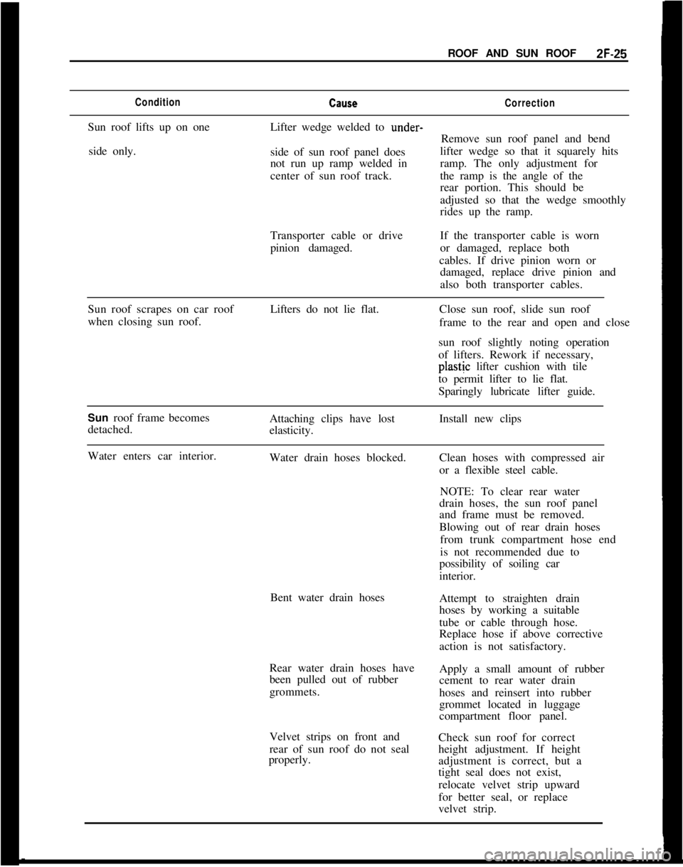
ROOF AND SUN ROOFZF-25ConditionCallseCorrectionSun roof lifts up on one
side only.Lifter wedge welded to under-
Remove sun roof panel and bend
side of sun roof panel doeslifter wedge so that it squarely hits
not run up ramp welded inramp. The only adjustment for
center of sun roof track.the ramp is the angle of the
rear portion. This should be
adjusted so that the wedge smoothly
rides up the ramp.
Transporter cable or drive
pinion damaged.If the transporter cable is worn
or damaged, replace both
cables. If drive pinion worn or
damaged, replace drive pinion and
also both transporter cables.
Sun roof scrapes on car roof
when closing sun roof.Lifters do not lie flat.Close sun roof, slide sun roof
frame to the rear and open and close
sun roof slightly noting operation
of lifters. Rework if necessary,plastjc lifter cushion with tile
to permit lifter to lie flat.
Sparingly lubricate lifter guide.
Sun roof frame becomes
detached.Attaching clips have lost
elasticity.Install new clips
Water enters car interior.
Water drain hoses blocked.
Bent water drain hoses
Rear water drain hoses have
been pulled out of rubber
grommets.
Velvet strips on front and
rear of sun roof do not seal
properly.Clean hoses with compressed air
or a flexible steel cable.
NOTE: To clear rear water
drain hoses, the sun roof panel
and frame must be removed.
Blowing out of rear drain hoses
from trunk compartment hose end
is not recommended due to
possibility of soiling car
interior.
Attempt to straighten drain
hoses by working a suitable
tube or cable through hose.
Replace hose if above corrective
action is not satisfactory.
Apply a small amount of rubber
cement to rear water drain
hoses and reinsert into rubber
grommet located in luggage
compartment floor panel.
Check sun roof for correct
height adjustment. If height
adjustment is correct, but a
tight seal does not exist,
relocate velvet strip upward
for better seal, or replace
velvet strip.
Page 149 of 625

2F-261973 OPEL SERVICE MANUALMAINTENANCE AND ADJUSTMENTSADJUSTING HEIGHT OF SUN ROOF PANEL
Adjust height of sun roof as follows:
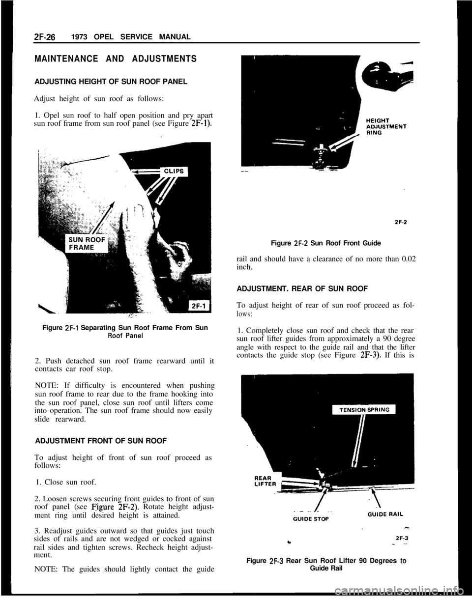
1. Opel sun roof to half open position and pry apart
sun roof frame from sun roof panel (see Figure
2F-1).Figure
ZF-1 Separating Sun Roof Frame From SunRoof Panel2. Push detached sun roof frame rearward until it
contacts car roof stop.
NOTE: If difficulty is encountered when pushing
sun roof frame to rear due to the frame hooking into
the sun roof panel, close sun roof until lifters come
into operation. The sun roof frame should now easily
slide rearward.
ADJUSTMENT FRONT OF SUN ROOF
To adjust height of front of sun roof proceed as
follows:
1. Close sun roof.
2. Loosen screws securing front guides to front of sun
roof panel (see Figure
2F-2). Rotate height adjust-
ment ring until desired height is attained.
3. Readjust guides outward so that guides just touch
sides of rails and are not wedged or cocked against
rail sides and tighten screws. Recheck height adjust-
ment.
NOTE: The guides should lightly contact the guideFigure
ZF-2 Sun Roof Front Guide
rail and should have a clearance of no more than 0.02
inch.
ADJUSTMENT. REAR OF SUN ROOF
To adjust height of rear of sun roof proceed as fol-
lows:1. Completely close sun roof and check that the rear
sun roof lifter guides from approximately a 90 degree
angle with respect to the guide rail and that the lifter
contacts the guide stop (see Figure
2F-3). If this is
Figure
2F-3 Rear Sun Roof Lifter 90 Degrees toGuide Rail
Page 151 of 625

2F-281973 OPEL SERVICE MANUAL
guides to height adjustment rings, loosen second
screw (see Figure 2F-6), and swing guides away from
guide rail.
NOTE: When swinging front guides inboard, be
careful not to change position of height adjustment
rings. It is suggested that the position of the height
adjustment rings be marked with a pencil prior to
loosening of front guide attaching screws.
5. Retighten remaining screw holding front guide in
position to prevent height adjustment rings from
turning.
6. Turn lifter guide tension springs 90 degrees in-
board and pull lifters out of sun roof panel brackets
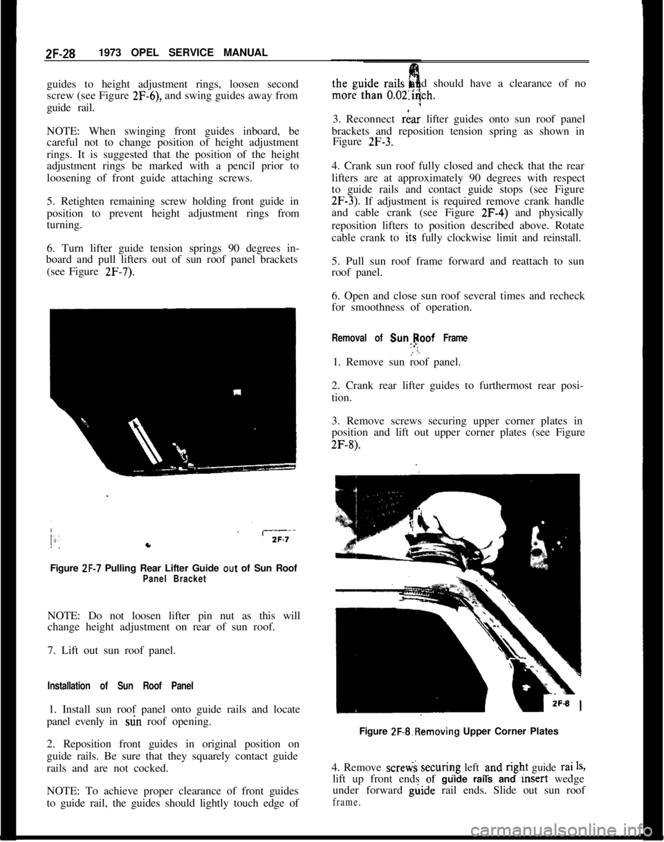
(see Figure
2F-7).Figure
ZF-7 Pulling Rear Lifter Guide out of Sun RoofPanel BracketNOTE: Do not loosen lifter pin nut as this will
change height adjustment on rear of sun roof.
7. Lift out sun roof panel.
Installation of Sun Roof Panel1. Install sun roof panel onto guide rails and locate
panel evenly in stin roof opening.
2. Reposition front guides in original position on
guide rails. Be sure that they squarely contact guide
rails and are not cocked.
NOTE: To achieve proper clearance of front guides
to guide rail, the guides should lightly touch edge ofdshould have a clearance of no
3. Reconnect
riar lifter guides onto sun roof panel
brackets and reposition tension spring as shown in
Figure
2F-3.4. Crank sun roof fully closed and check that the rear
lifters are at approximately 90 degrees with respect
to guide rails and contact guide stops (see Figure
2F-3). If adjustment is required remove crank handle
and cable crank (see Figure 2F-4) and physically
reposition lifters to position described above. Rotate
cable crank to its fully clockwise limit and reinstall.
5. Pull sun roof frame forward and reattach to sun
roof panel.
6. Open and close sun roof several times and recheck
for smoothness of operation.
Removal of Sunlpoof Frame1. Remove sun roof panel.
2. Crank rear lifter guides to furthermost rear posi-
tion.
3. Remove screws securing upper corner plates in
position and lift out upper corner plates (see Figure
2F-8).Figure 2F-&Removing Upper Corner Plates
4. Remove scretii securing left und
r@t guide rai1%lift up front ends
of- guide rails and msert wedge
under forward g&de rail ends. Slide out sun roof
frame.
Page 153 of 625

2F-301973 OPEL SERVICE MANUAL
3. Unscrew and remove upper and lower corner
plates (see Figure 2F-8).4. Unscrew and remove left and right upper cable
shields ans pull cable ends out of cable box.
5. Pull cable and rear lifter guides out of leftand
right guide rails.
Installation of Rear Guides and Cable1. Check both cables for wear or damage. If eigher
cable is defective, replace both cables.
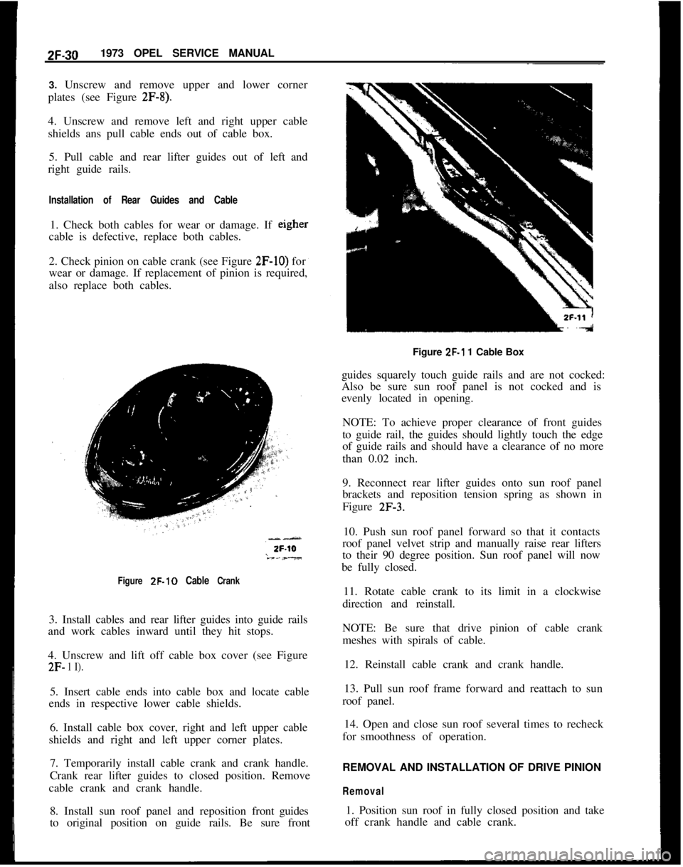
2. Check pinion on cable crank (see Figure
2F-IO) for
wear or damage. If replacement of pinion is required,
also replace both cables.
Figure ZF-10 Cable Crank3. Install cables and rear lifter guides into guide rails
and work cables inward until they hit stops.
4. Unscrew and lift off cable box cover (see Figure
2F- 1 I).5. Insert cable ends into cable box and locate cable
ends in respective lower cable shields.
6. Install cable box cover, right and left upper cable
shields and right and left upper corner plates.
7. Temporarily install cable crank and crank handle.
Crank rear lifter guides to closed position. Remove
cable crank and crank handle.
8. Install sun roof panel and reposition frontguides
to original position on guide rails. Be sure frontFigure
ZF-1 1 Cable Box
guides squarely touch guide rails and are not cocked:
Also be sure sun roof panel is not cocked and is
evenly located in opening.
NOTE: To achieve proper clearance of front guides
to guide rail, the guides should lightly touch the edge
of guide rails and should have a clearance of no more
than 0.02 inch.
9. Reconnect rear lifter guides onto sun roof panel
brackets and reposition tension spring as shown in
Figure
2F-3.10. Push sun roof panel forward so that it contacts
roof panel velvet strip and manually raise rear lifters
to their 90 degree position. Sun roof panel will now
be fully closed.
11. Rotate cable crank to its limit in a clockwise
direction and reinstall.
NOTE: Be sure that drive pinion of cable crank
meshes with spirals of cable.
12. Reinstall cable crank and crank handle.
13. Pull sun roof frame forward and reattach to sun
roof panel.
14. Open and close sun roof several times to recheck
forsmoothness of operation.
REMOVAL AND INSTALLATION OF DRIVE PINION
Removal1. Position sun roof in fully closed position and take
off crank handle and cable crank.
Page 158 of 625

SEATS, INTERIOR TRIM AND HEADLININGZG-35
2. Push off side panel trim pad. Trim pad is held in
position by a retaining button.
REMOVAL AND INSTALLATIONOF HEADLINING
Removal
1. Disconnect battery.
2. Lift out rear seat cushion (sedans only).
3. From trunk area, loosen tabs holding cardboard
against rear seat cross brace and lift out cardboard
(sedans only).
4. Pry up two tabs holding lower portion of rear seat
back in position, swing back of seat forward and lift
out (sedans only).
5. From trunk area pry out parcel shelf plastic retain-
ers and lift out parcel shelf (sedans only).
6. Remove rear-view mirror, sun visors, interior
lamp, assist straps and coat hooks. Remove front and
rear windows on all but Wagon Models. On Wagons,
remove the front window and the quarter windows.
7. Work door opening pinchweld finishing strip
away from pinchweld as far as necessary to expose
edge of headlining.
8. Start at: left or right windshield pillar and pry
headlining loose.
9. Roll back headlining to expose metal tabs securing
headlining listing wire to roof and unhook headhn-
ing front listing wire from metal tabs using a blunt
edge tool.
10. Pull loose the edges of headlining cemented to
door openings, rear quarter window openings, rear
quarter pillar and from under rear window rubber
channel. On rear quarter pillars, slightly bend down
cardboard of rear quarter trim pad to facilitate re-
moval. During removal, special care should be taken
not to tear headlining at seams.
11. After edges of headlining have been pulled loose,
tilt remaining listing wires with headlining forward
or rearward and pull listing wires free from side roof
rails. Lift out headlining and listing wires.
Installation1. Check secureness of noise insulation pad on inside
of roof panel and recement as necessary using asphalt
cement. If headlining is to be replaced, insert listing
wires into headlining according to their markings.
Progressing from the front listing wire to the rear
wire, the left ends of the wires are color coded as
follows:1st listing wire
- No marking, wire is thinner than
other wires
2nd listing wire
- Red
3rd listing wire
- Blue
4th listing wire
_ Green
5th listing wire
- Brown
6th listing wire
- White
2. Install 1st listing wire ends into retainer slots in-
side roof rails and hook listing wire into six metal
tabs above windshield. Lightly bend tabs with a ham-
mer as shown in Figure
2G-8.
HEAOLlN’lNdA-----
26-8Figure
2G-8 Headlining With 1st Listing Wire Hooked
Onto Metal Tabs
LISTINGWIRE
SECTIOND-D
4 26-9Figure 2G-9 2nd and 5th Listing Wire Attachment
Page 159 of 625

2G-361973 OPEL SERVICE MANUAL
3. Install and align the remaining five listing wires.
If required, caulk retainers of 2nd and 5th listing
wires so that wires run in a straight line transversally
under the roof. See Figure
2G-9.Figure ZG-10 3rd. 4th and 6th Listing Wire
Attachment4. Lightly pull headlining towards the rear and ce-
ment to the rear roof frame cross member and then
to the rear quarter pillars using rubber cement.
When pulling headlining toward rear be sure that the
listing wires are not pulled out of line. A folded clothshould be used to smooth down cemented portions
of headlining.
5. Cut off surplus headlining along rear window, rear
quarter windows, and windshield, leaving enough to
tit under rubber channels.
6. Cement surplus material to pinchweld flanges.
7. Cut off excess headliner around door openings and
cement trimmed edge to pinchweld flange using rub-
ber cement.
Figure 2G-12 Quarter Window and Lock Pillar Sealing
StripFigure
2G-1 1 Lock Pillar Shield Attaching ScrewsFigure 2G-13 Trim Pad and Retaining Button
Page 164 of 625

3116” SPACERSAFET‘;. CHAIN PLATE
(Dl -l/Z x 3INSTALLATION INSTRUCTIONS
1969
- 73 OPEL GT TRAILER HITCH LESS BALL
GROUP 7.068
STEP 1.REMOVE ONE RIGHT HAND AND ONE LEFT HAND
TAIL LAMP ASSEMBLY,
STEP 2.PLACE TIE BAR (C) UNDER THE REAR BODY
PANEL BY PULLING DOWN ON THE EXHAUST PIPES AND
SLIDING THE TIE BAR OVER THE PIPES AND INTO
POSITION. PLACE DRAW BAR (Al UNDER TIE BAR ICI
AND FASTEN WITH A
112 x 2” HEX BOLT WITH LOCK
WASHER AND NUT UNDER DRAW BAR (A). PLACE TIE
BAR (8) UNDER DRAW BAR IAl AND SAFETY CHAIN PLATE(DI UNDER TIE BAR
(B) AND FASTEN WITH A 112 ‘x 2-114”HEX BOLT WITH FLAT WASHER, LOCK WASHER AND NUT
BELOW SAFETY CHAIN PLATE IDI.
STEP 3. HOLD HITCH IN POSITION WITH TIE BAR (Cl
UNDE~R THE REAR BODY PANEL AND TIE BAR (RI
BETWEEN THE BUMPER GUARDS. USING THE HOLES IN
THE ENDS OF TIE BAR (Cl AS A GUIDE, LOCATE, MARK
AND DRILL TWO
112” HOLES IN THE VERTICAL PORTION
OF THE REAR BODY PANEL. PLACE THE 3/16” SPACERS
ON THE
112 x l-l/2 HEX BOLTS AND BY REACHING
THROUGH THE TAIL LAMP OPENINGS, INSERT THE BOLTS
THROUGH THE BODY PANEL AND TIE BAR (Cl AND
FASTEN WITH LOCK WASHER AND NUT.
STEP 4. ALIGN TIE BAR (8) BETWEEN THE
BUMP,ER GUARDS
AND LOCATE, MARK AND DRILL A 112~ HOLE THROUGH
BOTH SIDES OF THE BUMPER GUARD USING THE HOLES
IN TIE BAR IBI AS A GUIDE. MAINTAIN
112 lNCH.MlNlMUM
CLEARANCE BETWEEN TOP OF DRAW BAR.(A) AND
BOTTOM OF BACK-UP LIGHT. FASTEN TIE BAR
(Bl ,TO’THE BUMPER GUARDS WITH 112 x 3” BOLTS WITH TWO.112”
SPACERS AND ONE 318” SPACER INSIDE EACH BUMPER
GUARD. REPLACE TAIL LAMP ASSEMBLES.
TIGHTEN ALL
112” NUTS.TO A MAXIMUP,.TOROUE OF
60 FOOT LBS.
INSTALL BALL US1NG.A MAXIMUM.TOR~DUE OF
150 FOOT LBS.
MAXIMUM GROSS WEIGHT 1000 LBS.
MAXIMUM TONGUE WEIGHT 100 LBS.
MOST STATES PROHIBIT OBSTRUCTION OF LICENSE.
PLATES. BALL SHOULD BE REMOVED WHEN NOT IN
USE IF IT OBSTRUCTS A CLEAR VIEW.2H.8
Figure 2H-8 GT Trailer Hitch Installation
Page 165 of 625

FLVTRlJNK PLAT
DRAW BAR16x1-1/2 -DRAW‘ BAR EXTENSION-%GSAFETY CHAIN PLATE6INSTALLATION INSTRUCTIONS
1971
- 72 - 73 OPEL 1900 SERIES S/W
GROUP NO. 7.068
REMOVE LICENSE PLATE
STEP 1. ASSEMBLE HITCH AS ILLUSTRATED. HOLD
HITCH IS POSITION WITH FLOOR PLATE RESTING
AGAINST THE CROSS FRAME IN FRONT OF GAS TANK.
CENTER DRAW BAR SUPPORT ON THE REAR BODY
PANEL, RAISE UNTIL LEVEL.
STEP 2.MARK AND DRILL TWO
7116” HOLES IN REAR
BODY PANEL AND ATTACH AS SHOWN.
STEP 3.DRILL TWO
112” HOLES IN CROSS FRAME IN
FRONT OF THE GAS TANK AND CONTINUE DRILLING UP
THROUGH THE INNER FLOOR. NOTE: HOLD DRILL
VERTICAL WHILE DRILLING THROUGH THE INNER FLOOR.
ENLARGE BOTTOM HOLE SLIGHTLY TO ACCEPT SPACER.
STEP 4. ATTACH TRUNK PLATE AS ILLUSTRATED. PLACE
THE FLOOR PLATES ON THE 2
l/2” CARRIAGE BOLTS
AND INSERTS THROUGH THE OPENINGS
iN THE BACK OF
THE TRUNK WELL.INSERT SPACERS AS SHOWN AND
COMPLETE INSTALLATION.
REPLACE LICENSE PLATE.
TIGHTEN ALL
112” NUTS TO A MAXIMUM TORQUE OF
60 FOOT LBS. AND 7/16” NUTS TO A MAXIMUM OF
45 FOOT LBS.
INSTALL BALL USING A MAXIMUM TORQUE OF 150
FOOT LBS.
MAXIMUM GROSS WEIGHT 100 LBS
MAXIMUM TONGUE WEIGHT 100 LBS.
MOST STATES PROHIBIT OBSTRUCTION OF LICENSE
PLATES, BALL SHOULD BE REMOVED WHEN NOT IN
USE IF IT OBSTRUCTS A CLEAR VIEW.
ZH-9Figure
ZH-9 Opel 1900 Wagon Trailer Hitch Installation
Page 178 of 625

FRONT SUSPENSION3A- 11UPPER CONTROL ARM SHAFT
INNER SLEEVE
OUTER SLEEVE
RUBBER DAMPENIN
GUIDE SLEEVE
ABSORBER SUPPOR
SHOCK ABSORBER SUPPORT
ON FRONT SUSPENSION
CROSS MEMBER
-TOOTHED WASHER
l-UPPER CONTROL ARM
RUBBER BUSHINGS
PLATE WASHER
Figure
3A-19 Upper Control Arm Shaft and Bushings
placement part of lesser quality or substitute design.
Torque
valves must be used as specified during reas-
semb/y to assure proper retention of these parts.1. On installation of the upper control arm, make
sure that damper bushing with the rubber shoulder
on both sides is always located in the rear.
2. Attach upper control arm to cross member and
torque to
40 lb.ft. Always use new self-locking hex
nut. The upper control arm must be tightened in
horizontal position only. This applies also to all other
attaching joints in connection with rubber damper
bushings in the control arms of the front suspension
so that the rubber parts under load are in an almost
twist-free condition. This position exists, if the hooks
J-23697 are used.
3. Attach ball joint to upper control arm and torque
to 29
lb.ft.4. Install wheel and torque nuts to 65
lb.ft. Lowercar.LOWER CONTROL ARM REMOVAL AND
INSTALLATION
Removal GT
1. Raise car and support at rear of front frame rails.
2. Remove front wheel.
3. Remove cotter pin from castle nut on ball joint
stud and back off castle nut two (2) turns. Hit ball
stud a sharp blow to break it loose. DO NOT
REMOVE NUT.
4. Install spring compressor (J-21689) and compress
spring until a distance of
3-l/8 inches is achieved
between spring compressor and lower spring leaf.
5. Disconnect and compress shock absorber.
6. Support rail of spring compressor with a jack.
Remove lower control arm from frame cross mem-
ber. Nuts may have to be removed with a punch. See
Figure 3A-20. Discard the lock nuts.
7. Remove lower ball joint stud nut. Slightly lower
Page 181 of 625

3A. 141973 OPEL SERVkE MANUAL
Figure 3A-22 Caliper Removed and Hung by Wire
steering knuckle. Swing steering arm and tie rod to
the side.7. Remove castle nut cotter pin, unscrew nut and
pull steering knuckle off lower control arm ball joint.
Installation GTCAUTION: Fasteners are important attachingparts in
that they could affect the performance of
viral com-
ponents and systems, and/or could result in major
repair expense. They must be replaced with one of
the same part number or with an equivalent part if
replacement becomes necessary. Do not use a re-
placement part of lesser quality or substitute
desig.Torque values must be used as specified during reas-
sembly to assure proper retention of these parts.
1. Always replace paper gasket when installing dust
shield on steering knuckle. Lightly coat both surfaces
of paper gasket with chassis lubricant before installa-tion and torque attaching bolts to 47
lb.ft.2. Install lower ball joint in steering knuckle. Torque
castle nut to 54
Ib.ft. Install new cotter pin.
3. Attach shock absorber at lower end. Torque boltsto 30 lbs. ft.
4. Install upper ball joint. Torque castle nut to 29
lb.ft. Install new cotter pin.
5. Remove spring compressor.6. Install hub and disc on spindle and tighten spindle
nut as stated under MAINTENANCE AND AD-
JUSTMENTS in this section.
7. Install caliper on steering knuckle and torque boltsto 72
lb.ft. See Figure 3A-21.8. Install wheel and torque wheel nuts to 65
lb.ft.
Installation Opel 1900
- MantaCAUTION: Fasteners are important attachingparts in
that they could
affit the performance of vital com-
ponents and systems, and/or could result in
ma&repair expense. They must be replaced with one of
the same part number or with equivalent parts, ifrepfacement becomes necessary. Do not use a re-
placement part of lesser quality or substitute design.
Torque values must be used as specified during reas-
sembly to assure proper retention of these parts.
1. Attach steering knuckle to lower control arm ball
joint. Torque castle nut to 54
lb.ft.
2.
Atl,ach brake cover plate and steering arm to steer-ing knuckle. If required, install new paper gasket
between cover plate and steering knuckle. Care for
proper seat of T-head bolts. See Figure
3A-23.Figure 3A-23 Attaching Brake Cover Plate
3. Install front wheel hub and brake caliper.
4. Attach steering knuckle to upper control arm ball
joint. Torque castle nut to 40
lb.ft.5. Steering arm to steering knuckle
_ 58 lb.ft.6. Brake caliper to steering knuckle
- 72 lb.ft.7. Adjust front wheel bearing clearance.
8. Remove stands and lower car