fuel type OPEL GT-R 1973 Service Manual
[x] Cancel search | Manufacturer: OPEL, Model Year: 1973, Model line: GT-R, Model: OPEL GT-R 1973Pages: 625, PDF Size: 17.22 MB
Page 16 of 625
LUBRICATION AND MAINTENANCE OC-7SERVICESLUBE AND GENERAL MAINTENANCE
Vehicle operation under conditions such as heavy
dust, continuous short trips, use of other than un-
leaded or low lead fuels or pulling trailers, is not
considered normal use and therefore more frequent
maintenance will be required. Such additional
maintenance requirements are included where appli-
cable.
Engine OilChange each 4 months or
3,COO miles, whichever
occurs first, or each 2 months or
3,ooO miles when
the vehicle is operated under the following condi-
tions: (a) driving in dusty conditions, (b) trailer pull-
ing, (c) extensive idling or (d) short-trip operation at
freezing temperatures (with engine not thoroughly
warmed-up).Engine oils have a definite effect on ease of starting,
oil economy, combustion chamber deposits and en-
gine wear. It is recommended that a” oil which,
according to the label on the can is; (1) intended for
service SE and (2) passes car makers’ tests be used.
Oils confotming to these types contain detergent ad-
ditives. -
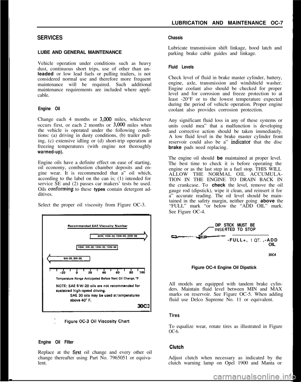
Select the proper oil viscosity from Figure OC-3.
Engine Oil FilterReplace at the first oil change and every other oil
change thereafter using Part No. 7965051 or equiva-
lent.
ChassisLubricate transmission shift linkage, hood latch and
parking brake cable guides and linkage.
Fluid LevelsCheck level of fluid in brake master cylinder, battery,
engine, axle, transmission and windshield washer.
Engine coolant also should be checked for proper
level and for corrosion and freeze protection to at
least -20°F or to the lowest temperature expected
during the period of vehicle operation. Proper engine
coolant also provides corrosion protection.
Any significant fluid loss in any of these systems or
units could mea” that a malfunction is developing
and corrective action should be taken immediately.
A low fluid level in the brake master cylinder front
reservoir could also be a” indtcator that the disc
brake pads need replacing.
The engine oil should be maintained at proper level.
The best time to check it is before operating the
engine or as the last step in a fuel stop. THIS WILL
ALLOW THE NORMAL OIL ACCUMULA-
TION IN THE ENGINE TO DRAIN BACK IN
the crankcase. To check the level, remove the oil
gauge rod (dipstick), wipe it clean, and reinsert it for
a” accurate reading. The oil level should be main-
tained in the safety margin, neither going above the
“FULL” mark “or below the “ADD OIL” mark.
See Figure OC-4.
DIP STICK MUST BE
INSERTED TO STOP
---L- -FULL+, 1 OT. ,-ADD
OIL
Figure OC-4 Engine Oil Dipstick
All models are equipped with tandem brake cylin-
ders. Maintain fluid level between MIN and MAX
marks on reservoir. See Figure OC-5. When adding
fluid use Delco Supreme No. 11 or equivalent.
TiresTo equalize wear, rotate tires as illustrated in Figure
OC-6.Adjust clutch when necessary as indicated by the
clutch warning lamp on Opel 1900 and Manta or
Page 67 of 625
1F. 46 1973 OPEL SERVICE MANUAL
’
/
Headlight High-Low Beam Control and Passing:
SignalI
When the headlights have been switched on, high
and low beam selection is made by raising the direc-
tional signal lever toward steering wheel. Each
ti&the lever is raised, beam position, will change.
When the headlights are not on, a flashing headlight
signal may be given by raising and lotiering the di-
rectional signal lever. With the headlights on and
inlow beam position, raising and lowering the direc-
tional signal lever will also cause the headlights to
flash.
Fog Light SwitchAll Rallye models are equipped with two white f?g
lights mounted below the front bumper.
The fog light toggle switch is located on the
insty-ment cluster to the left of the temperature and
fuelgauge cluster.
/
The fog lights can be turned off at any time by the
toggle switch, but can only be tyrned on when: :
1. The ignition switch on or the
?gine running.!
2. The fog light toggle switch lower half is pushed
in.3. The parking lights and/or low beam headlights
are
OKThe fog lights are automatically turned off if the
ignition switch is on and the headlights are switched
to high beam position.
Courtesy LightThe courtesy light illuminates the interior of the Car
when any door is opened. The courtesy light can also
be turned on with all doors closed by tilting the l&s.
GT Headlamp MechanismThe concealed headlamps are moved mechanically.
Pushing actuating lever on left side of console opens
headlamps and pulling lever closes headlamps. Two
(2) meshing gear segments convert the movement, of
the lever to a rotation of 180 degrees. The pivots of
the headlamps lie below the centerline so that with
headlamps in closed position, the headlamp housing
is flush with front sheet metal. Refer to Group 110,
Section “F”, for service procedures on the GT head-
lamp mechanism.
A white indicator lamp in the instrument panel lights
if the headlamps are not completely opened lorclosed The switches of the headlamp electrical sys-
tem are located behind the left headlamp operating,
mechanism.
MAINTENANCE AND ADJUSTMENTSHEADLAMP AIMING
The headlamps must be properly aimed in order to
obtain maximum road illumination and safety that
has been built into the headlighting equipment. With
the Guide T-3 type sealed beam units, proper aiming
is even more important because the increased range
and power of this lamp make even slight variations
from recommended aiming hazardous to approach-
ing motorists. The headlamps must be checked for
proper aim whenever a sealed beam unit is replaced
and after an adjustment or repairs of the front end
sheet metal assembly.
Regardless of method used for checking headlamp
aim, car must be at normal weight, that is, with gas,
oil, water, and spare tire. Tires must be uniformly
inflated to specified pressure. If car will regularly
carry an unusual load in rear compartment, or a
trailer, these loads should be on car when headlamps
are checked. Some States have special requirements
for headlamp aiming adjustment, and these require-
ments should be known and observed.
Horizontal and vertical aiming of each seal beam
unit is provided by two adjusting screws which move
the mounting ring in the body against the tension of
the coil spring. There is no adjustment for focus,
since the sealed beam unit is set for proper focus
during manufacturing assembly.
MAJOR REPAIRHEADLIGHT SWITCH
- OPEL 1900. MANTA
Removal1. Remove instrument cluster cover panel. See Sec-
tion H.
2. Compress retaining springs and pull switch out.
See Figure 1 F-
1.3. Pull multiple socket off switch.
Installation
1: Plug multiple socket in switch and push switch in
panel until clips lock in place.
2. Replace instrument cover and secure with two (2)
screws.
Page 300 of 625
ENGINE MECHANICAL AND MOUNTS6A- 9
The engine does not rest on the front suspension
cross member as in the Opel 1900 and Manta but on
a separate cross member. On removal and installa-
tion of the engine the front suspension cross member
need not be detached.
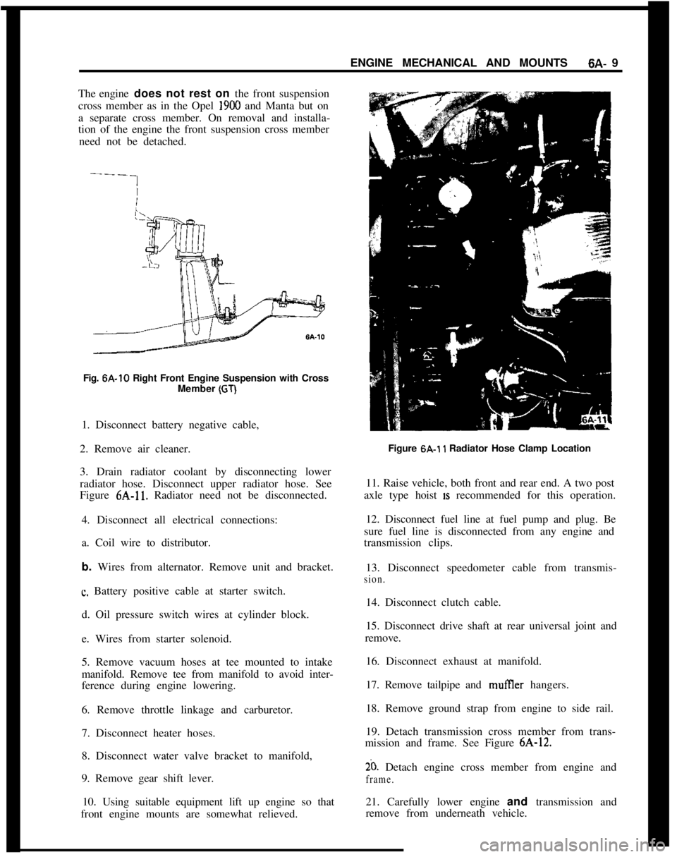
Fig. 6A-10 Right Front Engine Suspension with Cross
Member
(GT)1. Disconnect battery negative cable,
2. Remove air cleaner.
3. Drain radiator coolant by disconnecting lower
radiator hose. Disconnect upper radiator hose. See
Figure 6A-11. Radiator need not be disconnected.
4. Disconnect all electrical connections:
a. Coil wire to distributor.
b. Wires from alternator. Remove unit and bracket.
c. Battery positive cable at starter switch.
d. Oil pressure switch wires at cylinder block.
e. Wires from starter solenoid.
5. Remove vacuum hoses at tee mounted to intake
manifold. Remove tee from manifold to avoid inter-
ference during engine lowering.
6. Remove throttle linkage and carburetor.
7. Disconnect heater hoses.
8. Disconnect water valve bracket to manifold,
9. Remove gear shift lever.
10. Using suitable equipment lift up engine so that
front engine mounts are somewhat relieved.Figure 6A.1
1 Radiator Hose Clamp Location
11. Raise vehicle, both front and rear end. A two post
axle type hoist
IS recommended for this operation.
12. Disconnect fuel line at fuel pump and plug. Be
sure fuel line is disconnected from any engine and
transmission clips.
13. Disconnect speedometer cable from transmis-
sion.14. Disconnect clutch cable.
15. Disconnect drive shaft at rear universal joint and
remove.
16. Disconnect exhaust at manifold.
17. Remove tailpipe and mufIler hangers.
18. Remove ground strap from engine to side rail.
19. Detach transmission cross member from trans-
mission and frame. See Figure 6A-12.
20. Detach engine cross member from engine and
frame.21. Carefully lower engine and transmission and
remove from underneath vehicle.
Page 327 of 625
6C- 361973 OPEL SERVICE MANUAL
FUEL SYSTEM
ALL MODELS
CONTENTS
Subject
DESCRIPTION AND OPERATION:
Fuel Pump. . . . . . . . . . . . . . . . . . . . . . . . . . . . . . . . . . . . . . . . . . . . . . . . . . . . . . . . . . . . . . . . .. . . . . . . . . . .Evaporation Control System
. . . . . . . . . . . . . . . . . . . . . . . . . . . . . . . . . . . . . . . . . .DIAGNOSIS:
(Not Applicable)
MAINTENANCE AND ADJUSTMENTS:
Cleaning Fuel Pump Strainer.,....................................
*.Evaporation Control System
. . . . . . . . . . . , . . . . . . . . . . . . . . . . . . . . . . . . . . . . . .MAJOR REPAIR:
Fuel Tank
. . . . . . . . . . . . . . . . . . . . . . . . . . . . . . . . . . . . . . . . . . . . . . . . . . . . . . . . . . . . . . . . . . . . . . . . . . . . . .Fuel Lines and Fuel Tank Gauge Units
. . . . . . . . . . . . . . . . . . . . . .SPECIFICATIONS:
Fuel System Specifications
. . . . . . . . . . . . . . . . . . . . . . . . . . . . . . . . . . . . . . . . . . .Page No.6C-366C-376C-376C-386C-396C-416C-41
DESCRIPTION AND OPERATION
FUEL PUMPThe 1.9 liter engine uses a push rod type fuel pump.
The push rod is actuated by an eccentric on the
distributor shaft. The push rod is held in contact
with the eccentric at all times by a push rod spring.
Each time the push rod is on the high part of the
eccentric, the lighter diaphragm spring will push the
diaphragm to replace any fuel used in the carburetor.
The diaphragm seldom operates through a full
stroke; under normal driving conditions, the dia-
phragm moves only a few tenths of an inch.
Fuel pump pressure is determined by the compres-
sion of the diaphragm spring. Low pressure or pres-
sure leak- down generally indicates a leaky
diaphragm or check valves.
Two holes in the lower part of the fuel pump serve
to ventilate the space below the diaphragm and to
drain any fuel which may have entered. If any fuel
comes from these holes, this indicates a defective
diaphragm.When replacing the fuel pump, make sure the asbe-
stos spacer is in place with a gasket on each side. See
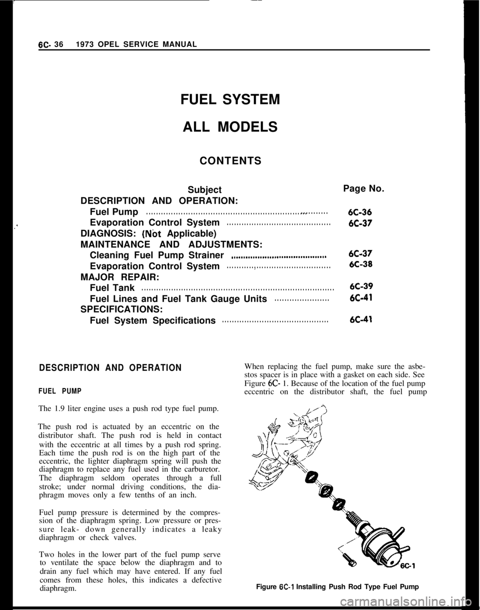
Figure 6C- 1. Because of the location of the fuel pump
eccentric on the distributor shaft, the fuel pump
Figure
6C-1 Installing Push Rod Type Fuel Pump
Page 328 of 625
FUEL SYSTEMSC- 37
must always be removed before the distributor can be
removed.
EVAPORATION CONTROL SYSTEM1. The function of the fuel evaporation control sys-
tem is to absorb the fuel vapors developing in the fuel
tank, especially when vehicle is parked, due to at-
mospheric pressure and temperature influences, and
to release these fuel vapors during vehicle operation.
2. This system utilizes the property of the activated
carbon to absorb and expel fuel vapors. The activated
carbon container is installed on the left front side of
the engine compartment. The fuel tank has a
non-vented tiller cap. Vent hoses are joined in the area of
the tank. A plastic evaporation line leads from there
along vehicle underbody to the activated carbon con-
tainer.
3. A small tube above the throttle valve body con-
nects the carburetor to the activated carbon con-
tainer. In this way, the fuel vapor collected in the
activated carbon container is fed through the carbu-
retor into the combustion chambers during engine
operation.
4. The carburetor is provided with an internal and
outside ventilation, the activated carbon container is
also connected to the outside ventilation (only effec-
tive when engine is idling). In this way, the fuel
vapors escaping to the outside during engine idle are
collected by the activated carbon container and fed
into the combustion chambers.
5. The vent lines are connected to the upper part of
the activated carbon container. Fresh air enters
through a foam rubber filter at the lower part andflows, together with the fuel vapor, to the carburetor.
Metered bores in the hose fittings of the fuel tank
control the air
- and fuel vapor flow through the
activated carbon container to the carburetor, and the
pressure release in the fuel tank and ensure complete
purging of the carbon container.
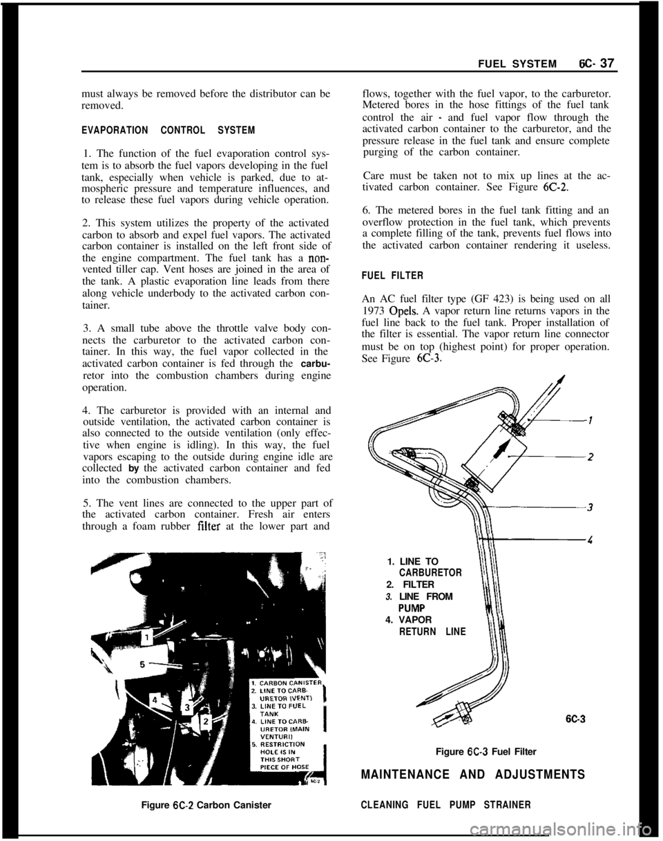
Care must be taken not to mix up lines at the ac-
tivated carbon container. See Figure
6C-2.6. The metered bores in the fuel tank fitting and an
overflow protection in the fuel tank, which prevents
a complete filling of the tank, prevents fuel flows into
the activated carbon container rendering it useless.
FUEL FILTERAn AC fuel filter type (GF 423) is being used on all
1973 Opels. A vapor return line returns vapors in the
fuel line back to the fuel tank. Proper installation of
the filter is essential. The vapor return line connector
must be on top (highest point) for proper operation.
See Figure
6C-3.1. LINE TO
CARBURETOR2. FILTER
3. LINE FROM
4. VAPOR
RETURN LINE
6C-3Figure
6C-3 Fuel Filter
MAINTENANCE AND ADJUSTMENTSFigure
6C-2 Carbon CanisterCLEANING FUEL PUMP STRAINER
Page 332 of 625

FUEL SYSTEM6C- 41
covered with sound deadening compound. See Fig-
ure
6C-10.7. Remove fuel tank vent hose and tiller hose. See
Figure 6C- 11.
8. Remove fuel tank attaching bolts and gauge wire
and remove tank.
Installation
1. Install tank and tighten attaching bolts.
2. Replace gauge wire. Install vent hose, making cer-
tain it is not kinked and seal vent hose hole in floor.
3. Install spare tire support attaching brackets, sup-
port panel, hold-down, and brackets.
4. Install spare tire and jack.
5. Install fuel line and rubber cap.
6. Connect battery.FUEL LINES. FUEL GAUGE TANK UNITS
All fuel lines are plastic and have an outside diameter
of
,240 inches. Unlike metal lines, plastic lines are
not flared.
When replacing a plastic line, place the line in hot
water to make it flexible. Using the old line as a
pattern, form the new line. Let the line cool com-
pletely, then route it in the same location as the old
line. To prevent chafing against the underbody, nine
(9) rubber grommets are placed at points on the line
between the fuel tank and the fuel pump. When re-
placing fuel gauge tank units, coat gasket on both
sides and first threads of attaching screws with seal-
ing compound.
CLEANING FUEL TANK
1. Remove fuel tank.
2. Empty fuel tank through filler neck.
3. Remove fuel gauge tank unit, together with suc-
tion tube and screen. Clean screen and blow out from
cover side. Flush fuel tank.
SPECIFICATIONSFuel Tank Capacity (Gallons)
Opel 1900 and Manta
....................................................................................................11.9GT
....................................................................................................................................13.2FuelGaugeType
........................................................................................................Electrical
Fuel Pump Type
......................................................................................................Mechanical
Fuel Pump Drive
..................................................................................Eccentric on Camshaft
Fuel Pump Pressure at 1950 (RPM)................................................................3.1 to 3.7 P.S.I.FuelFilter
............................................................................................................In-LineFilter
Page 347 of 625

6E- 561973 OPEL SERVICE MANUAL
valve stop screw. Loosen the stop screw until the
valve is completely closed. Turn the screw in l/4turn from closed position, hold, and tighten lock nut.
This is done to insure that the throttle blade will not
stick closed. See Figure
6E-30.PUMPFigure 6E-30 Adjusting Secondary Throttle Valve Gap
24. Install accelerator pump connecting rod in lower
hole of primary throttle shaft lever and cotter pin in
outboard hole at accelerator pump actuating lever
end. Paying attention to proper arrangement of cot-
ter pin and washers. See Figure
6E-2.25. With throttle plate completely closed, there
should be no clearance between the pump levei and
the pump plunger rod.
26. If a clearance is present, loosen 4 accelerator
Figure
6E-31 Accelerator Pump CoverFigure 6C32 Accelerator Pump Cover
pump cover retaining screws and allow the
dia-’phragm spring to push plunger against lever so that
a zero clearance exists. Then retighten the screws.
See Figures
6E-3 1 and 6E-32.27. Insert accelerator pump discharge nozzle so that
the bent tube end points into suction channel of the
primary barrel.
28. Fill the bowl with fuel.
29. With fuel in bowl, slowly open the throttle and
observe the accelerator pump pressure relief valve
exhaust ports and where it seats into the bowl. See
Figure
6E-33. Fuel should not be bleeding back into
the bowl from the exhaust ports or where the relief
valve seats, but a steady stream of fuel should dis-
charge from the discharge nozzle.
30. With fuel in bowl, rapidly open the throttle atid
observe the exhaust ports of the pressure relief valve.
See Figure
6E-33. Fuel should~exhaust’from the ac-
celerator pump pressure relief valve exhaust ports.
3 1. If the pressure relief valve malfunctions, remove
it and replace with a new one.
32. No float adjustment is possible, so check position
of float arm by comparing with a new float of thesame carburetor type. If float arm is bent, replace
float.
Page 349 of 625
6E- 581973 OPEL SERVICE MANUAL
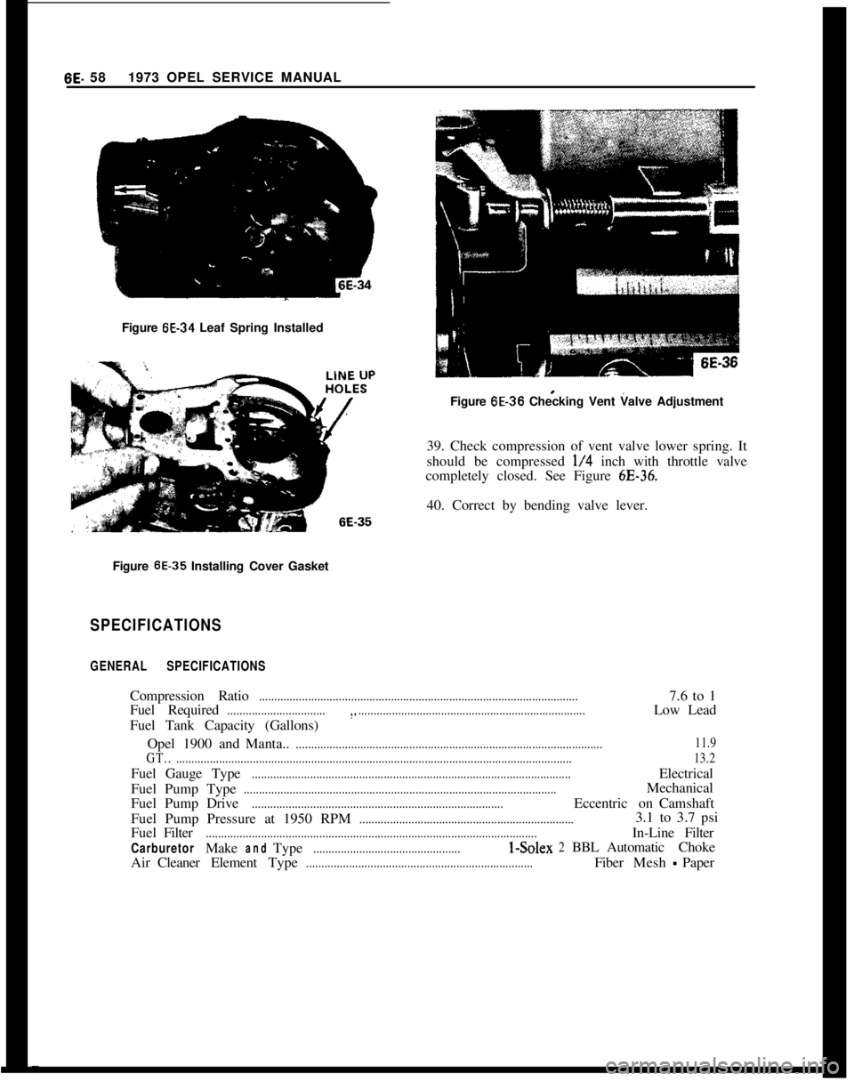
Figure 6E-34 Leaf Spring Installed
1 6E-36
Figure 6E-36 Checking Vent Valve Adjustment
39. Check compression of vent valve lower spring. It
should be compressed
l/4 inch with throttle valve
completely closed. See Figure
6E-36.40. Correct by bending valve lever.
Figure
6E-35 Installing Cover Gasket
SPECIFICATIONS
GENERAL SPECIFICATIONSCompression Ratio
........................................................................................................7.6 to 1
Fuel Required
................................(...........................................................................Low Lead
Fuel Tank Capacity (Gallons)
Opel1900andManta..
....................................................................................................11.9
GT...................................................................................................................................13.2Fuel Gauge Type
........................................................................................................Electrical
FuelPumpType
......................................................................................................Mechanical
FuelPumpDrive
..................................................................................EccentriconCamshaft
Fuel Pump Pressure at 1950 RPM
......................................................................3.1 to 3.7 psi
FuelFilter
............................................................................................................In-LineFilter
CarburetorMakeandType................................................I-Solex2BBLAutomaticChoke
AirCleanerElementType
..........................................................................FiberMesh-Paper