fuses OPEL GT-R 1973 Service Manual
[x] Cancel search | Manufacturer: OPEL, Model Year: 1973, Model line: GT-R, Model: OPEL GT-R 1973Pages: 625, PDF Size: 17.22 MB
Page 29 of 625

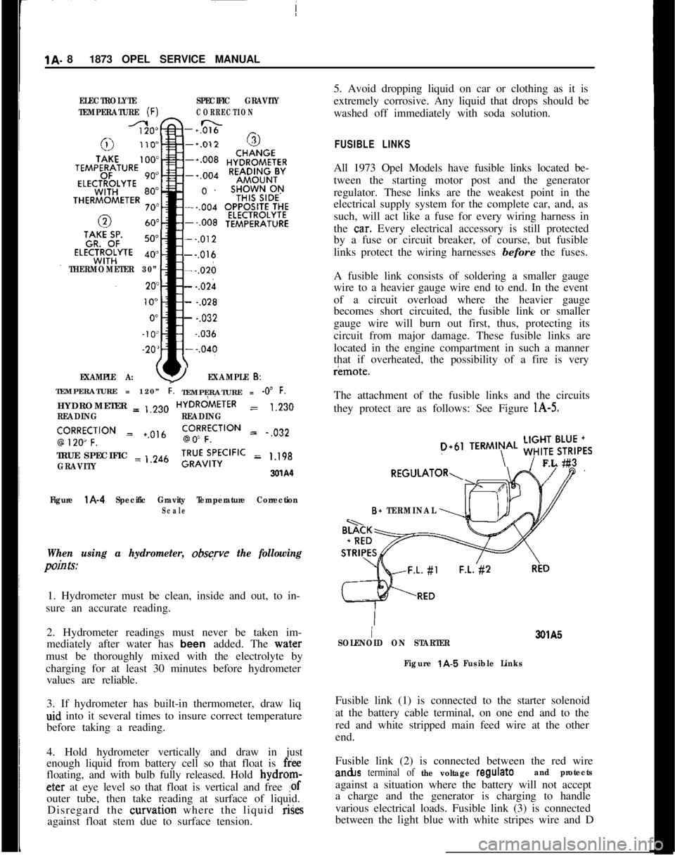
1A. 81873 OPEL SERVICE MANUALELECTROLYTESPECIFIC GRAVITY
TEMPERATURE
(F)CORRECTION
-+0&&n _
THERMOMETER 30”
EXAMPLE A:
--,012---,016---,026
- -.02h
- -.028
- -.032~
-.036
YEXAMPLE 6:TEMPERATURE = 120”
i.TEMPERATURE = -0” F.HYDROMETER = ,,230HYDRdiETER
= 1.230
READINGREADING
‘,9R2Ro~CF;‘“” = +.0,6go!RFfCilON = .,032
TRUE SPECIFIC = ,.246
GRAVITY;RU”v;,‘;CIFIC = 1.198
3xA‘l
Figure
l A-4 Specific Gravity Temperature CorrectionScale
When using a hydrometer, obsqve the following
pain Is:1. Hydrometer must be clean, inside and out, to in-
sure an accurate reading.
2. Hydrometer readings must never be taken im-
mediately after water has been added. The water
must be thoroughly mixed with the electrolyte by
charging for at least 30 minutes before hydrometer
values are reliable.
3. If hydrometer has built-in thermometer, draw liq
aid into it several times to insure correct temperature
before taking a reading.
4. Hold hydrometer vertically and draw in just
enough liquid from battery cell so that float is
freefloating, and with bulb fully released. Hold bydrom-eter at eye level so that float is vertical and free
!ofouter tube, then take reading at surface of liquid.
Disregard the curvation where the liquid rises
against float stem due to surface tension.5. Avoid dropping liquid on car or clothing as it is
extremely corrosive. Any liquid that drops should be
washed off immediately with soda solution.
FUSIBLE LINKSAll 1973 Opel Models have fusible links located be-
tween the starting motor post and the generator
regulator. These links are the weakest point in the
electrical supply system for the complete car, and, as
such, will act like a fuse for every wiring harness in
the
ca.r. Every electrical accessory is still protected
by a fuse or circuit breaker, of course, but fusible
links protect the wiring harnesses before the fuses.
A fusible link consists of soldering a smaller gauge
wire to a heavier gauge wire end to end. In the event
of a circuit overload where the heavier gauge
becomes short circuited, the fusible link or smaller
gauge wire will burn out first, thus, protecting its
circuit from major damage. These fusible links are
located in the engine compartment in such a manner
that if overheated, the possibility of a fire is veryr¬e.
The attachment of the fusible links and the circuits
they protect are as follows: See Figure
l A-5.
D+61TERMIN\AL ;;!$6,,FL #3
B+ TERMINAL
I3QlA5
SOLENOID ON STARTER
Figure
t A-5 Fusible LinksFusible link (1) is connected to the starter solenoid
at the battery cable terminal, on one end and to the
red and white stripped main feed wire at the other
end.
Fusible link (2) is connected between the red wirean&s
terminal of the voltage regulateand protectsagainst a situation where the battery will not accept
a charge and the generator is charging to handle
various electrical loads. Fusible link (3) is connected
between the light blue with white stripes wire and D
Page 532 of 625

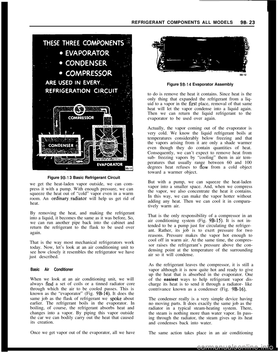
REFRIGERANT COMPONENTS ALL MODELS96.23Figure 96-l 3 Basic Refrigerant Circuit
we get the heat-laden vapor outside, we can com-
press it with a pump. With enough pressure, we can
squeeze the heat out of “cold” vapor even in a warm
room. An ordinary.radiator will help us get rid of
heat.
By removing the heat, and making the refrigerant
into a liquid, it becomes the same as it was before, So,
we can run another pipe back into the cabinet and
return the refrigerant to the flask to be used over
again.
That is the way most mechanical refrigerators work
today. Now, let’s look at an air conditioning unit to
see how closely it resembles the refrigerator we have
just described.
Basic Air ConditionerWhen we look at an air conditioning unit, we will
always find a set of coils or a tinned radiator core
through which the air to be cooled passes. This is
known as the “evaporator” (Fig.
9B-14). It does the
same job as the flask of refrigerant we
spok.e about
earlier. The refrigerant boils in the evaporator. In
boiling, of course, the refrigerant absorbs heat and
changes into a vapor. By piping this vapor outside
the car we can bodily carry out the heat that caused
its creation.
Once we get vapor out of the evaporator, all we haveFigure 98.14 Evaporator Assembly
to do is remove the heat it contains. Since heat is the
only thing that expanded the refrigerant from a liq-
uid to a vapor in the first place, removal of that same
heat will let the vapor condense into a liquid again.
Then we can return the liquid refrigerant to the
evaporator to be used over again.
Actually, the vapor coming out of the evaporator is
very cold. We know the liquid refrigerant boils at
temperatures considerably below freezing and that
the vapors arising from it are only a shade warmer
even though they do contain quantities of heat.
Consequently, we can’t expect to remove heat from
sub- freezing vapors by “cooling” them in air tem-
peratures that usually range between 60 and 100
degrees heat refuses to
flow from a cold object
toward a warmer object.
But with a pump, we can squeeze the heat-laden
vapor into a smaller space. And, when we compress
the vapor, we also concentrate the heat it contains.
In this way, we can make the vapor hotter without
adding any heat. Then we can cool it in compara-
tively warm air.
That is the only responsibility of a compressor in an
air conditioning system (Fig.
9B-15). It is not in-
tended to be a pump just for circulating the refriger-
ant. Rather, its job is to exert pressure for two
reasons. Pressure makes the vapor hot enough to
cool off in warm air. At the same time, the compres-
sor raises the refrigerant’s pressure above the con-
densing point at the temperature of the surrounding
air so it will condense.
As the refrigerant leaves the compressor, it is still a
vapor although it is now quite hot and ready to give
up the heat that is absorbed in the evaporator. One
of the easiest ways to help refrigerant vapor dis-
charge its heat is to send it through a radiator- like
contrivance known as a condenser (Fig. 9B-16).
The condenser really is a very simple device having
no moving parts. It does exactly the same job as the
radiator in a typical steam-heating system. There,
the steam is nothing more than water vapor. In pass-
ing through the radiator, the steam gives up its heat
and condenses back into water.
The same action takes place in an air conditioning