lock OPEL GT-R 1973 Service Manual
[x] Cancel search | Manufacturer: OPEL, Model Year: 1973, Model line: GT-R, Model: OPEL GT-R 1973Pages: 625, PDF Size: 17.22 MB
Page 10 of 625
GENERAL INt=ORMATION OA-1
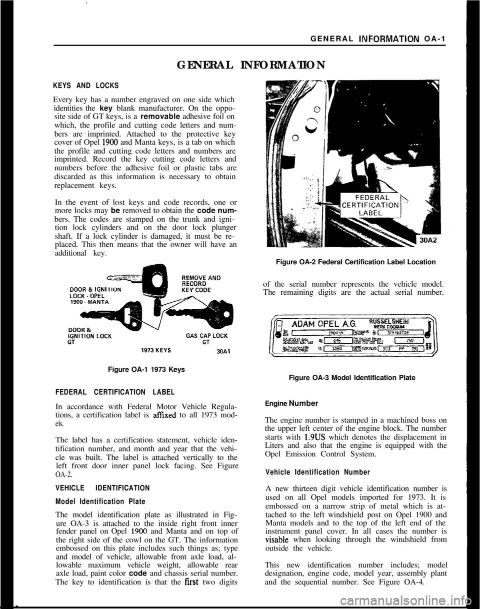
GENERAL INFORMATIONKEYS AND LOCKSEvery key has a number engraved on one side which
identities the key blank manufacturer. On the oppo-
site side of GT keys, is a removable adhesive foil on
which, the profile and cutting code letters and num-
bers are imprinted. Attached to the protective key
cover of Opel
1900 and Manta keys, is a tab on which
the profile and cutting code letters and numbers are
imprinted. Record the key cutting code letters and
numbers before the adhesive foil or plastic tabs are
discarded as this information is necessary to obtain
replacement keys.
In the event of lost keys and code records, one or
more locks may be removed to obtain the code num-
bers. The codes are stamped on the trunk and igni-
tion lock cylinders and on the door lock plunger
shaft. If a lock cylinder is damaged, it must be re-
placed. This then means that the owner will have an
additional key.REMOVE ANDDOOR &
IGNIKEY CODELOCK. OPELIGNITION
LOCKGAS CAP LOCKGTGT
Figure OA-1 1973 Keys
FEDERAL CERTIFICATION LABELIn accordance with Federal Motor Vehicle Regula-
tions, a certification label is
affIxed to all 1973 mod-
els.The label has a certification statement, vehicle iden-
tification number, and month and year that the vehi-
cle was built. The label is attached vertically to the
left front door inner panel lock facing. See Figure
OA-2.
VEHICLE IDENTIFICATION
Model Identification PlateThe model identification plate as illustrated in Fig-
ure OA-3 is attached to the inside right front inner
fender panel on Opel
1900 and Manta and on top of
the right side of the cowl on the GT. The information
embossed on this plate includes such things as; type
and model of vehicle, allowable front axle load, al-
lowable maximum vehicle weight, allowable rear
axle load, paint color code and chassis serial number.
The key to identification is that the first two digitsFigure OA-2 Federal Certification Label Location
of the serial number represents the vehicle model.
The remaining digits are the actual serial number.
Figure OA-3 Model Identification Plate
Engine Number
The engine number is stamped in a machined boss on
the upper left center of the engine block. The number
starts with 1.9US which denotes the displacement in
Liters and also that the engine is equipped with the
Opel Emission Control System.
Vehicle Identification NumberA new thirteen digit vehicle identification number is
used on all Opel models imported for 1973. It is
embossed on a narrow strip of metal which is at-
tached to the left windshield post on Opel 1900 and
Manta models and to the top of the left end of the
instrument panel cover. In all cases the number isvisable when looking through the windshield from
outside the vehicle.
This new identification number includes; model
designation, engine code, model year, assembly plant
and the sequential number. See Figure OA-4.
Page 18 of 625
LUBRICATION AND MAINTENANCE OC-9
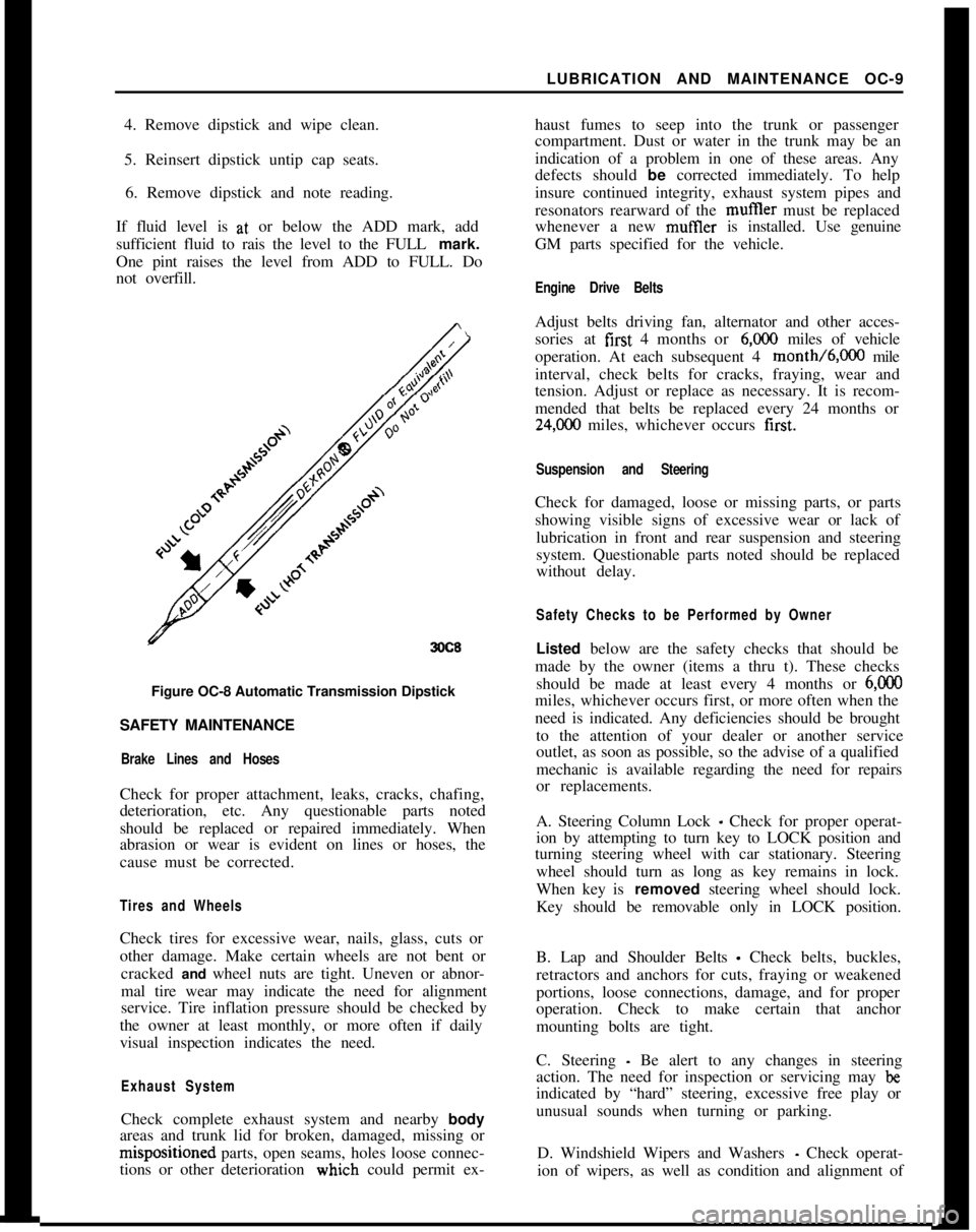
4. Remove dipstick and wipe clean.
5. Reinsert dipstick untip cap seats.
6. Remove dipstick and note reading.
If fluid level is at, or below the ADD mark, add
sufficient fluid to rais the level to the FULL mark.
One pint raises the level from ADD to FULL. Do
not overfill.
3OC8Figure OC-8 Automatic Transmission Dipstick
SAFETY MAINTENANCE
Brake Lines and HosesCheck for proper attachment, leaks, cracks, chafing,
deterioration, etc. Any questionable parts noted
should be replaced or repaired immediately. When
abrasion or wear is evident on lines or hoses, the
cause must be corrected.
Tires and WheelsCheck tires for excessive wear, nails, glass, cuts or
other damage. Make certain wheels are not bent or
cracked and wheel nuts are tight. Uneven or abnor-
mal tire wear may indicate the need for alignment
service. Tire inflation pressure should be checked by
the owner at least monthly, or more often if daily
visual inspection indicates the need.
Exhaust SystemCheck complete exhaust system and nearby body
areas and trunk lid for broken, damaged, missing orm&positioned parts, open seams, holes loose connec-
tions or other deterioration wiuch could permit ex-haust fumes to seep into the trunk or passenger
compartment. Dust or water in the trunk may be an
indication of a problem in one of these areas. Any
defects should be corrected immediately. To help
insure continued integrity, exhaust system pipes and
resonators rearward of the muftler must be replaced
whenever a new mufIler is installed. Use genuine
GM parts specified for the vehicle.
Engine Drive BeltsAdjust belts driving fan, alternator and other acces-
sories at first 4 months or
6,ooO miles of vehicle
operation. At each subsequent 4 month/6,000 mile
interval, check belts for cracks, fraying, wear and
tension. Adjust or replace as necessary. It is recom-
mended that belts be replaced every 24 months or
24,C00 miles, whichever occurs first.
Suspension and SteeringCheck for damaged, loose or missing parts, or parts
showing visible signs of excessive wear or lack of
lubrication in front and rear suspension and steering
system. Questionable parts noted should be replaced
without delay.
Safety Checks to be Performed by OwnerListed below are the safety checks that should be
made by the owner (items a thru t). These checks
should be made at least every 4 months or
6,ooOmiles, whichever occurs first, or more often when the
need is indicated. Any deficiencies should be brought
to the attention of your dealer or another service
outlet, as soon as possible, so the advise of a qualified
mechanic is available regarding the need for repairs
or replacements.
A. Steering Column Lock
_ Check for proper operat-
ion by attempting to turn key to LOCK position and
turning steering wheel with car stationary. Steering
wheel should turn as long as key remains in lock.
When key is removed steering wheel should lock.
Key should be removable only in LOCK position.
B. Lap and Shoulder Belts
- Check belts, buckles,
retractors and anchors for cuts, fraying or weakened
portions, loose connections, damage, and for proper
operation. Check to make certain that anchor
mounting bolts are tight.
C. Steering
- Be alert to any changes in steering
action. The need for inspection or servicing may
beindicated by “hard” steering, excessive free play or
unusual sounds when turning or parking.
D. Windshield Wipers and Washers
- Check operat-
ion of wipers, as well as condition and alignment of
Page 19 of 625
CC-10 1973 OPEL SERVICE MANUAL
wiper blades. Check amount and direction of fluid
sprayed by washers during use.,
E. Defrosters - Check performance by moving con-
trols to “DEF” and noting
am$nmt of air directed
against the windshield.
I
F. Wheel Alignment and
Balabce - In addition to
abnormal tire wear, the need fbr wheel alignment
service may be indicated by a pull to the right or
!eftwhen driving on a straight and level road. The need
for wheel balancing is usually
iddicated by a vibra-
tion of the steering wheel or
se;+ tihile driving at
normal highway speeds.I
IG. Brakes
- Be alert to illumiriation of the brake
warning light or changes in braking action,
SUCK as
repeated pulling to one side, unusual sounds when
braking or increased brake pedal travel. Any of thesecould indicate the need for
brakk system inspection
and/or service.
H. Parking Brake and Transmission “PARK”
Mechanism
- Check parking brake holding ability by
parking on a fairly steep hill and restraining the vehi-
cle with the parking brake only.
eon cars with auto-
matic transmissions, check the holding ability of the
“PARK” mechanism by releasing all brakes after
the transmission selector lever hak been placed in the“P” position.
I. Glass
- Check for broken, scrritched, dirty or da-
maged glass on vehicle that
coulld obscure vision’or
become an injury hazard.
J. Lights and Buzzers
- Check all instrument panel
illuminating and warning lights,’ seat belt reminder
light and buzzer, ignition key
b&er, interior lights,
license plate lights, side marker! lights, headlamps,
parking lamps, tail lamps, brake lights, turn signals,
backup lamps, and hazard warding flashers. Have
someone observe operation of
&ach exterior light
while you activate the controls: The operation of
instrument panel warning lights is covered in the
“Starting and Operating“ section of your
Own&%
Manual.K. Transmission Shift Indicator
‘- Check to be sure
automatic transmission shift
indiCator accurately i”-
dicates the shift position selected.
I
CAUTION: Before making thk check below,I
be sure to have a clear dist&e ahead and:
behind the car, set the parking brake and
firmly apply the foot brake.
Do not depress
accelerator pedal. Be prepared to
turn off ’
ignition switch
immediat+y if engine
should start.L. Starter Safety Switch (Automatic Transmissibn
Cars)
- Check starter safety switch by placing the
transmission in each of the driving gears while
at-tempting to start the engine. The starter should oper-ate only in the Park (“P”) or Neutral (“N”)
positions.
M. Horn
- Blow the horn occasionally to be sure thatit works. (Ignition switch must be in the “ON” posi-
tion.)
N. Seat Back Latches
- Check to see that seat back
latches are holding by pulling forward on the top of
each folding seat back.
0. Rearview Mirrors and Sun Visors
- Check that
friction joints are properly adjusted so mirrors and
sun visors stay in the selected position.
P. Door Latches
- Check for positive closing, latch-
ing and locking.
Q. Hood Latches - Check to make sure hood closesfirmly by pressing on the hood at the latching point
after each closing. Check also for broken, damaged
or missing parts which might prevent secure latch-
ing.R. Fluid Leaks
- Check for fuel, water, oil or other
fluid leaks by observing the ground beneath the vehi-cle after it has been parked for a while. If gasoline
fumes or fluid are noticed at any time, the cause
should be determined and corrected without delay
because of the possibility of fire.
S. Exhaust System
- Be alert to any change in the
sound of the exhaust system or a smell of fumes
which may indicate a leak.
Head Restraints
- Check that no head restraint
components are missing, damaged or loose. (Does
not apply to GT Models).
Disc BrakesCheck brake pads and condition of rotors while
wheels are removed during tire rotation. (Note belowregarding more frequent checks also applies to disc
brakes.)
Parking and Drum BrakesCheck drum
brake linings and other internal brake
components at each wheel (drums, wheel cylinders,
etc.). Parking brake adjustment also should be
checked whenever drum brake linings are checked.
NOTE: More frequent checks should be
made if driving conditions a.nd habits result
in frequent brake application. When brakes
require relining, it is recommended thatyou use those genuine General Motors
parts specified for your car,and Delco fluid
as required.
Page 27 of 625
j
/lA- 61973 OPEL SERVICE MANUAL
Do not overfill, as electrolyte may
be sprayed out by
gassing or may overtlow due to heat expansion dur:
ing charging.
If distilled water is not available, it is better to add
clean, mineral-free tap water than to allow the
elec2trolyte level to remain below the top of the plates:
In freezing weather the water should be added just
before using the car or otherwise charging the bat-
tery so that the water will be mixed with the acid
before it is allowed to stand in freezing temperatures.
If it is found necessary to add water to the
batterimore frequently than about every
1,ooO miles and the
quantity of water added per cell is’ excessive, check
setting of voltage regulator and adjust, if necessary:
Abnormal water loss is an indication that the battery
is being overcharged.
Inspect Battery, Mounting and Cables
Check outside of battery for damage or signs of se&ous abuse such as broken case or broken covers:
Check inside of battery by removing the vent caps
and inspecting for signs of abuse
stich as electrolyte
level too low to see, or bad or unusual odors. If
battery shows signs of serious damage or abuse, it
should be replaced.
Check the battery hold down bolts to make certain
that battery is securely held in place. The nut should
be drawn up to 20 lbs. in.;excessjve tightening may
distort or crack the battery case.If the top of battery is dirty or the hold down str?e
is corroded, clean thoroughly with a brush dipped
IFammonia or soda solution. Care must be used td
prevent any solution from getting into battery
cellslAfter the foaming of solution stops, flush off witli
clean water and dry thoroughly. If hold down strap
is corroded it should be painted with acid-resisting
paint after cleaning.
Check battery cables to make certain they are tight
at bracket and junction block. If a connection is
found loose it should be cleaned before being tight;ened as arcing and corrosion may have taken place
in the loose connection. Check condition of cables
and replace if badly corroded or frayed.
Special attention must be given to,the battery posi-
tive cable position to eliminate the possibility of con-
tact with the exhaust manifold on the 1.1 liter engine.
The cable clamp must be rotated clockwise as neces-
sary for the cable to run at a 45 degree angle toward
the right wheelhouse panel.
Cleaning Cable Terminals
If loose connections are found by inspection, or highresistance is found by voltage test, disconnect the
cable for thorough cleaning of terminals. When
removing a corroded cable terminal from battery
post, do not pry against battery case or hammer on
terminal to break it loose, since either practice will
result in broken cell covers. Use a screw-type termi-
nal puller if terminal cannot be loosened by hand.
Thoroughly clean all corrosion from disconnected
battery cable terminals and terminal posts, using
suitable wire brushes. If wire brushes are not availa-
ble, corroded terminals may be cleaned by brushing
with a strong soda solution, using care not to get
solution into battery cells.
If
cabbz strands are broken, corroded, or loose in
terminals, the cable should be replaced with the cor-
rect cable to insure ample capacity.
To prevent corrosion of battery terminals and con-
nections, apply a coating of petroleum jelly over the
battery post and cable terminals after cables have
been installed on terminals.
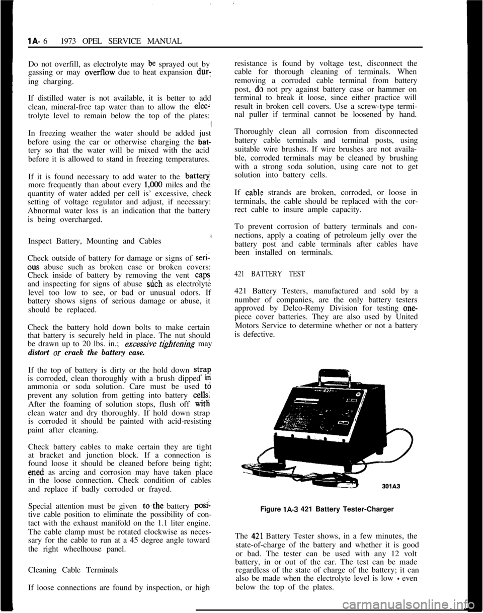
421 BATTERY TEST421 Battery Testers, manufactured and sold by a
number of companies, are the only battery testers
approved by Delco-Remy Division for testing one-
piece cover batteries. They are also used by United
Motors Service to determine whether or not a battery
is defective.
Figure lA-3 421 Battery Tester-Charger
The
42,l Battery Tester shows, in a few minutes, the
state-of-charge of the battery and whether it is good
or bad. The tester can be used with any 12 volt
battery, in or out of the car. The test can be made
regardless of the state of charge of the battery; it can
also be made when the electrolyte level is low
- even
below the top of the plates.
Page 32 of 625
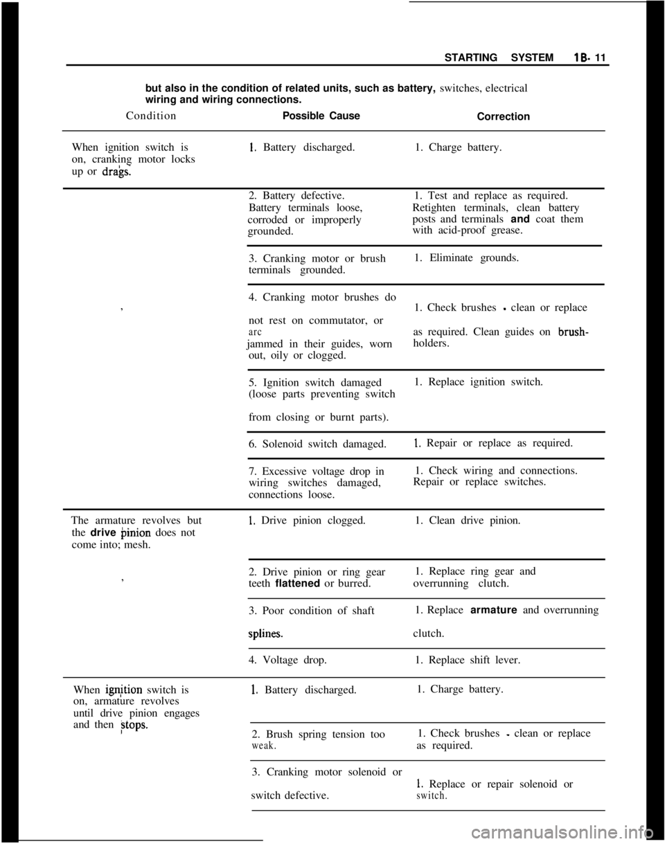
I
STARTING SYSTEMlB- 11
but also in the condition of related units, such as battery, switches, electrical
wiring and wiring connections.
ConditionPossible Cause
Correction
When ignition switch is1. Battery discharged.1. Charge battery.
on, cranking motor locks
up or
dra’gs.2. Battery defective.1. Test and replace as required.
Battery terminals loose,Retighten terminals, clean battery
corroded or improperlyposts and terminals and coat them
grounded.with acid-proof grease.
3. Cranking motor or brush1. Eliminate grounds.
terminals grounded.
I
4. Cranking motor brushes do
,
1. Check brushes
- clean or replace
not rest on commutator, or
arcas required. Clean guides on brush-
jammed in their guides, wornholders.
out, oily or clogged.
5. Ignition switch damaged1. Replace ignition switch.
(loose parts preventing switch
I
from closing or burnt parts).
6. Solenoid switch damaged.
1. Repair or replace as required.
7. Excessive voltage drop in1. Check wiring and connections.
wiring switches damaged,Repair or replace switches.
connections loose.
The armature revolves but
1. Drive pinion clogged.1. Clean drive pinion.
the drive binion does not
come into; mesh.
2. Drive pinion or ring gear1. Replace ring gear and
,
teeth flattened or burred.overrunning clutch.
I
3. Poor condition of shaft1. Replace armature and overrunningsplines.clutch.
4. Voltage drop.1. Replace shift lever.
When ignjtion switch is
1. Battery discharged.1. Charge battery.
on, armature revolves
until drive pinion engages
and then
Btops.2. Brush spring tension too1. Check brushes - clean or replace
weak.as required.
3. Cranking motor solenoid or
1. Replace or repair solenoid or
switch defective.
switch.
Page 33 of 625
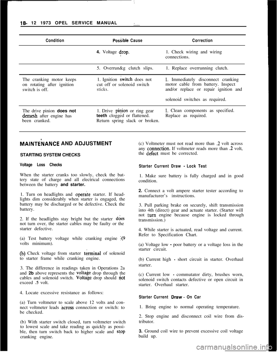
19- 12 1973 OPEL SERVICE MANUAL :ConditionPosiible CauseCorrection4. Voltage drop.1. Check wiring and wiring
connections.
5. Overrun&g clutch slips.1. Replace overrunning clutch.
The cranking motor keeps
on rotating after ignition
switch is off.1. Ignition
{witch does not
cut off or solenoid switch
sticks.
1, Immediately disconnect cranking
motor cable from battery. Inspect
and/or replace or repair ignition and
solenoid switches as required.
The drive pinion does notdemesh after engine has
been cranked.1. Drive pinion or ring gear
1. Clean components as specified.
teeth clogged or flattened.Replace as required.
Return spring slack or broken.MAlNTEilANCE AND ADJUSTMENT
/
STARTING SYSTEM CHECKS
Voltage Loss ChecksWhen the starter cranks too slowly, check the bat-
tery state of charge and all electrical connections
between the battery and starter.
1. Turn on headlights and
opera’te starter. If head-
lights dim considerably when starter is engaged, the
battery may be discharged or be defective. Check the
battery.
2. If the headlights stay bright but the starter d&s
not turn over, the starter cables may be faulty or the
starter defective.
(a) Test battery voltage while cranking engine
1(9volts minimum).
(b) Check voltage from starter tkrminal of solenoid
to starter frame while cranking engine.
3. The difference in readings taken in Operations 2a
and 2b above represents the
volt& drop through the
cables and solenoid switch. Voltdge drop should
Gotexceed
.5 volt.
4. Locate excessive resistance as follows:
(a) Turn voltmeter to scale above 12 volts and con-
nect voltmeter leads
across connection or switch: to
be checked.
(b) With starter switch closed, turn voltmeter switch
to lowest scale and take reading as quickly as possi-
ble, then turn switch back to higher scale and stop
cranking engine.(c) Voltmeter must not read more than
.2 volt across
any
c:onnection. If voltmeter reads more than .2 volt,
the
d~efect must be corrected.
Starter Current Draw - Lock Test1. Make sure battery is fully charged and in good
condition.
2. Connect a volt ampere starter tester according to
manufacturer’s instructions.
3. Pull parking brake on securely, shift transmission
into 4th (direct) gear and actuate starter. (Starter will
not
t,urn engine because engine is locked through
transmission.)
4. While starter is actuated, read voltage and current.
Refer to Specification Chart.
(a) Voltage low
_ poor battery or a voltage loss in the
starter circuit.
(b) Current high
- short circuit in starter. Overhaul
starter.
(c) Current low
- commutator dirty, brushes worn,
solenoid switch contacts defective or open circuit in
starter. Overhaul starter.
Starter Current Draw. On Car1. Bring engine to normal operating temperature.
2. Stop engine and disconnect coil wire from dis-
tributor.
3. Ground coil wire to prevent excessive coil voltage
build up.
Page 34 of 625
STARTING SYSTEMlB- 13
4. Connect test equipment and, with transmission in
neutral, turn engine over until voltage stabilizes.
Note read.ings.5. Current draw should be between 90-130 amperes.
I3. Remove end frame from field frame and pull both
insulating tubes out of field frame.
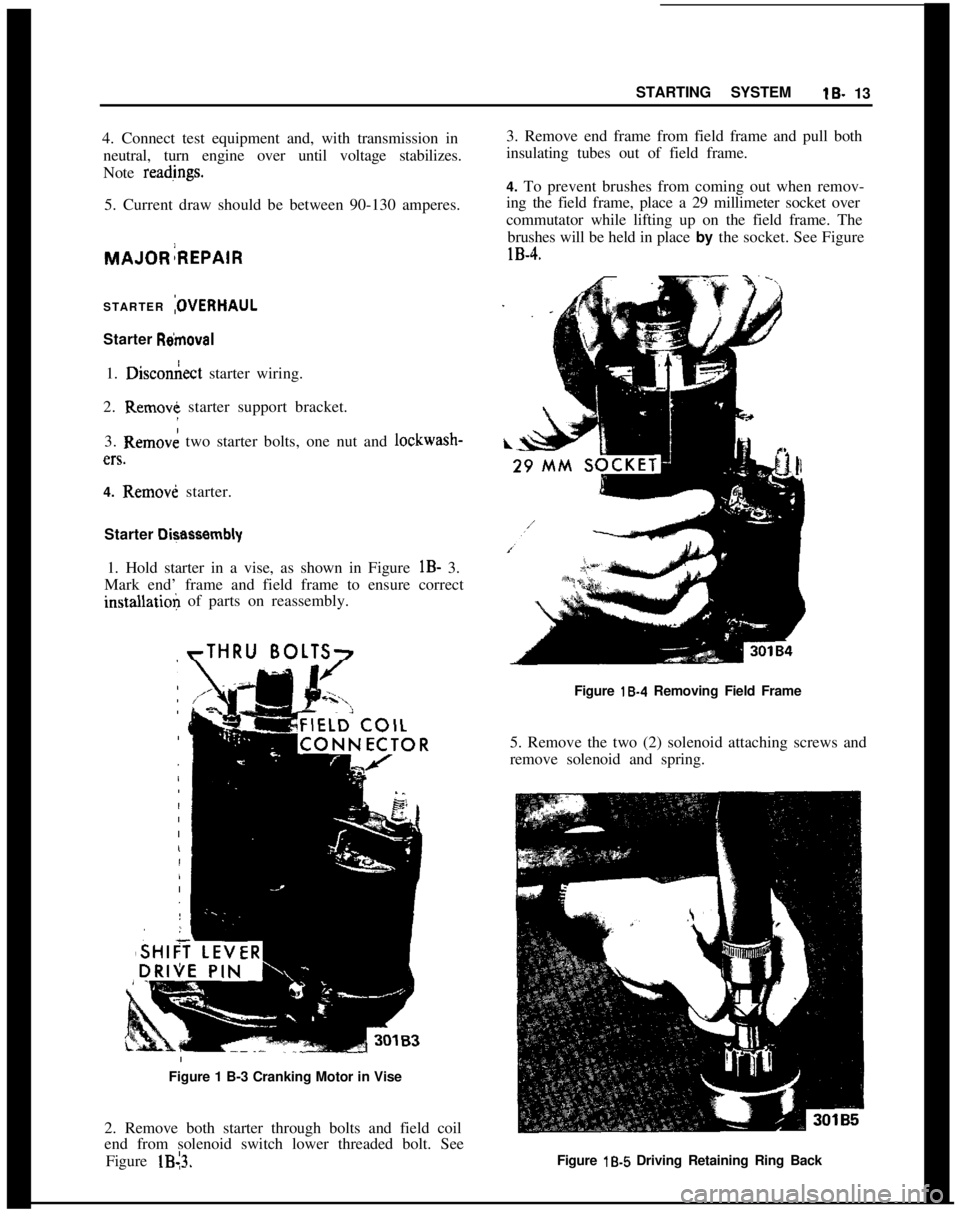
4. To prevent brushes from coming out when remov-
ing the field frame, place a 29 millimeter socket over
commutator while lifting up on the field frame. The
brushes will be held in place by the socket. See FigurelB-4.
STARTER
:OVERHAULStarter
R&~moval1.
Dixon&t starter wiring.
2. Remove starter support bracket.
3. Removk two starter bolts, one nut and lockwash-en.
4. Removi starter.
Starter
Di+assembly1. Hold starter in a vise, as shown in Figure
lB- 3.
Mark end’ frame and field frame to ensure correctinstallatioli of parts on reassembly.
rTHRU BOLTS7Figure
18-4 Removing Field Frame
5. Remove the two (2) solenoid attaching screws and
remove solenoid and spring.
Figure 1 B-3 Cranking Motor in Vise
2. Remove both starter through bolts and field coil
end from solenoid switch lower threaded bolt. See
Figure lB13.Figure
lb5 Driving Retaining Ring Back
Page 35 of 625
lB- 14 1973 OPEL SERVICE MANUAL !
6. Remove shift lever shaft and: lift armature aid
shift lever assembly.
7. Drive back retaining ring on armature shaft. See
Figure
lB-5.
8. Take the lock ring, retaining ring, and
over&-
ning clutch and pinion off armature shaft. Cheqk
groove in shaft for burrs and remove with a soft tile.
Cleaning and Inspecting Parts
1. Clean and check all parts. Replace defective parts.
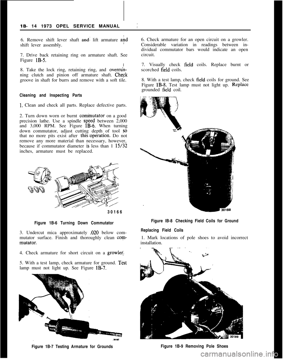
2. Turn down worn or burnt
cominutator on a good
precision lathe. Use a spindle
speed between 2,000
and 3,000 RPM. See Figure
lB-6. When turning
down commutator, adjust cutting depth of tool
so
that no more pits exist after this:operation. Do not
remove any more material than necessary, however,
because if commutator diameter
is less than 1 15/32
inches, armature must be replaced.
30166
Figure 1B-6 Turning Down Commutator
3. Undercut mica approximately ,020 below com-
mutator surface. Finish and thoroughly clean
corn-
mutator.
I
4. Check armature for short circuit on a
growler.
5. With a test lamp, check armature for ground.
Test
lamp must not light up. See Figure
IB-7.
Figure 1B-7 Testing Armature for Grounds
j
6. Check armature for an open circuit on a growler.
Considerable variation in readings between in-
dividual commutator bars would indicate an open
circuit.
7. Visually check
field coils. Replace burnt or
scorched
field coils.
8. With a test lamp, check
field coils for ground. See
Figure
IB-8. Test lamp must not light up. Replzice
grounded field coil.
Figure lB-8 Checking Field Coils for Ground
Replacing Field Coils
1. Mark locations of pole shoes to avoid incorrect
installation.
Figure 1B-9 Removing Pole Shoes
Page 37 of 625
lB- 16 1973 OPEL SERVICE MANUAL
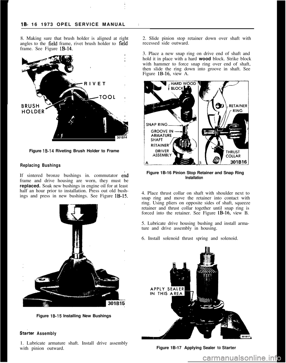
8. Making sure that brush holder is aligned at right
angles to the
field frame, rivet brush holder to field
frame. See Figure
lB-14.
RIVET
Figure 18.14 Riveting Brush Holder to Frame i
Replacing Bushings
If sintered bronze bushings in. commutator ehd
frame and drive housing are worn, they must be
replaced. Soak new bushings in engine oil for at least
half an hour prior to installation. Press out old bush-
ings and press in new bushings. See Figure
lB-15.
Figure 18.15 Installing New Bushings
St& Assembly
1. Lubricate armature shaft. Install drive assembly
with pinion outward. 2. Slide pinion stop retainer down over shaft with
recessed side outward.
3. Place a new snap ring on drive end of shaft and
hold it in place with a hard
wood block. Strike block
with hammer to force snap ring over end of shaft,
then slide the ring down into groove in shaft. See
Figure
lB-16, view A.
7
(
I
I
E-.
Figure 1B-16 Pinion Stop Retainer and Snap Ring
Installation
4. Place thrust collar on shaft with shoulder next to
snap ring and move the retainer into contact with
ring. Using pliers on opposite sides of shaft, squeeze
retainer and thrust collar together until snap ring is
forced into the retainer. See Figure
lB-16, view B.
5. Lubricate drive housing bushing and install arma-
ture and drive assembly in housing.
6. Install solenoid thrust spring and solenoid.
Figure 1B-17 Applying Sealer to Starter
Page 38 of 625
STARTING SYSTEMlB- 17
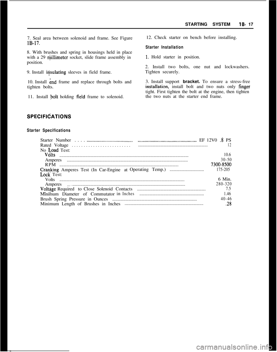
7. Seal area between solenoid and frame. See FigurelB-17.
8. With brushes and spring in housings held in place
with a 29 @llimeter socket, slide frame assembly in
position.
9. Install i+ulating sleeves in field frame.
10. Install knd frame and replace through bolts and
tighten bolts.
11. Install bolt holding field frame to solenoid.
SPEClFltjATlONS
Starter SpecificationsStarterNumber. . . .
.._.._..._...........................RatedVoltage
. . . . . . . . . . . . . . . . . . . . . . . . .No voad Test:
...............................................EF 12V0 .8 PS
.....................................................................12Volts
................................................................................................................................10.6Amperes
........................................................................................................................30-50RPM
......................................................................................................................7300-8500Cranking Amperes Test (InCar-Engine atOperating Temp.)
..................................175-205
Lock Test:
Volts
............................................................................................................................6 Min.
Amperes
....................................................................................................................280-320Volt$geRequiredtoCloseSolenoidContacts
....................................................................7.5MinimumDiameterof Commutatorin
Inches................................................................1.46Brush Spring Pressure in Ounces
....................................................................................40-46Minimum Length of Brushes in Inches...............................................................................2812. Check starter on bench before installing.
Starter Installation
1. Hold starter in position.
2. Install two bolts, one nut and lockwashers.
Tighten securely.
3. Install support bracket. To ensure a stress-freeintitallation, install bolt and two nuts only finger
tight. First tighten the bolt at the engine, then tighten
the two nuts at the starter end frame.