service interval OPEL GT-R 1973 Service Manual
[x] Cancel search | Manufacturer: OPEL, Model Year: 1973, Model line: GT-R, Model: OPEL GT-R 1973Pages: 625, PDF Size: 17.22 MB
Page 17 of 625
IoC-91973 OPEL SERVICE MANUAL
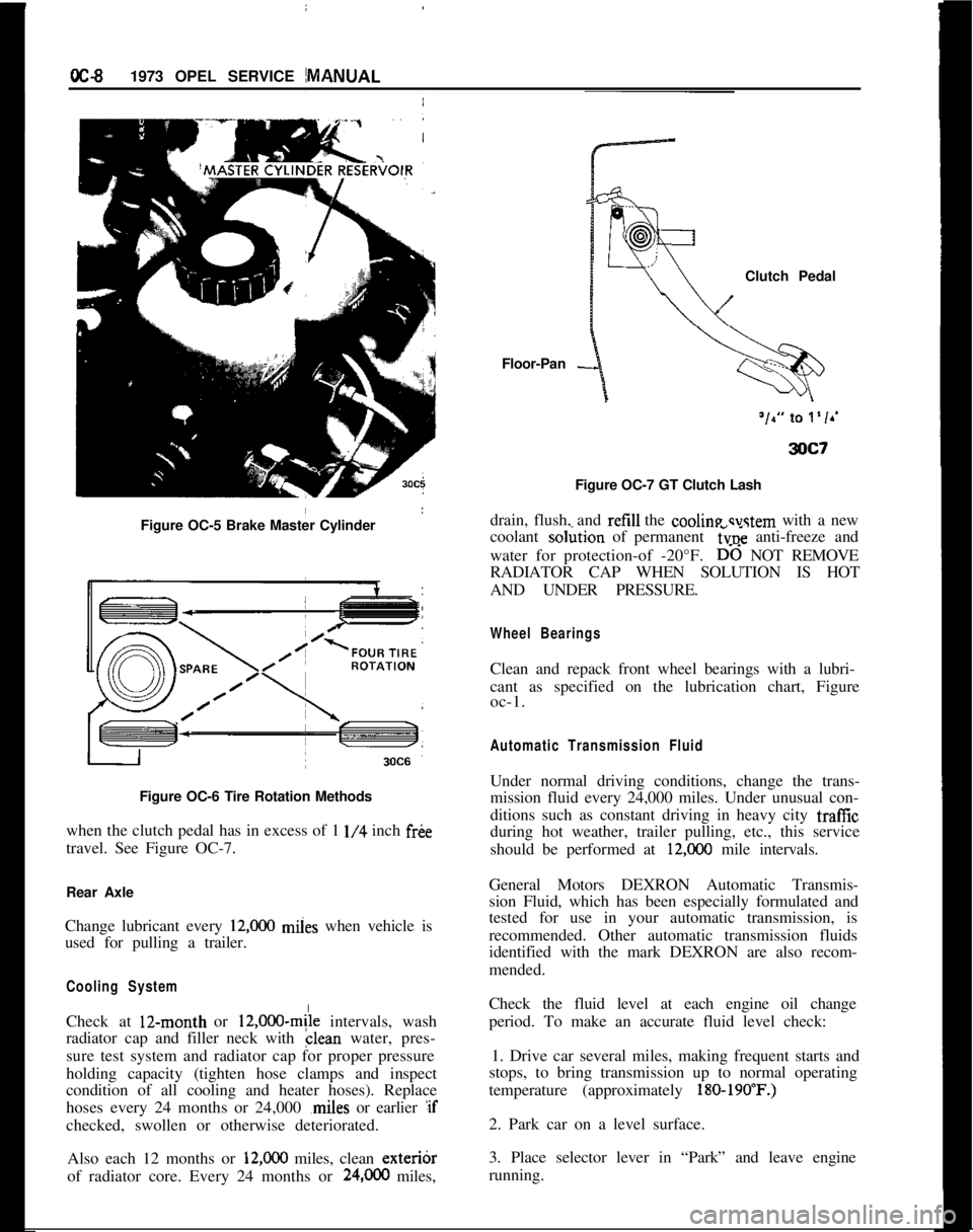
Figure OC-5 Brake Master Cylinder
I
Figure OC-6 Tire Rotation Methods
when the clutch pedal has in excess of 1
l/4 inch fr&
travel. See Figure OC-7.
Rear Axle
Change lubricant every
12,ooO miies when vehicle is
used for pulling a trailer.
Cooling SystemCheck at 12-month or
12,000~mile intervals, wash
radiator cap and filler neck with clean water, pres-
sure test system and radiator cap for proper pressure
holding capacity (tighten hose clamps and inspect
condition of all cooling and heater hoses). Replace
hoses every 24 months or 24,000 ,miles or earlier :if
checked, swollen or otherwise deteriorated.
Also each 12 months or
12,ooO miles, clean exteribr
of radiator core. Every 24 months or
24,OCO miles,Floor-Pan
-Clutch Pedal
Figure OC-7 GT Clutch Lash
drain, flush, and refill the cooline svstem with a new
coolant so&ion of permanent
6~; anti-freeze and
water for protection-of -20°F.
D-6 NOT REMOVE
RADIATOR CAP WHEN SOLUTION IS HOT
AND UNDER PRESSURE.
Wheel BearingsClean and repack front wheel bearings with a lubri-
cant as specified on the lubrication chart, Figure
oc-1.
Automatic Transmission FluidUnder normal driving conditions, change the trans-
mission fluid every 24,000 miles. Under unusual con-
ditions such as constant driving in heavy city traffic
during hot weather, trailer pulling, etc., this service
should be performed at
12,COO mile intervals.
General Motors DEXRON Automatic Transmis-
sion Fluid, which has been especially formulated and
tested for use in your automatic transmission, is
recommended. Other automatic transmission fluids
identified with the mark DEXRON are also recom-
mended.
Check the fluid level at each engine oil change
period. To make an accurate fluid level check:
1. Drive car several miles, making frequent starts and
stops, to bring transmission up to normal operating
temperature (approximately
180-190’F.)2. Park car on a level surface.
3. Place selector lever in “Park” and leave engine
running.
Page 18 of 625
LUBRICATION AND MAINTENANCE OC-9
4. Remove dipstick and wipe clean.
5. Reinsert dipstick untip cap seats.
6. Remove dipstick and note reading.
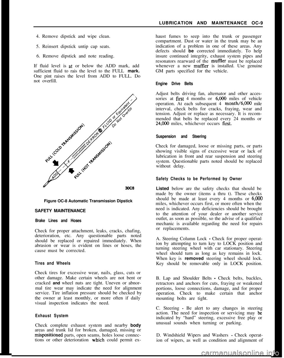
If fluid level is at, or below the ADD mark, add
sufficient fluid to rais the level to the FULL mark.
One pint raises the level from ADD to FULL. Do
not overfill.
3OC8Figure OC-8 Automatic Transmission Dipstick
SAFETY MAINTENANCE
Brake Lines and HosesCheck for proper attachment, leaks, cracks, chafing,
deterioration, etc. Any questionable parts noted
should be replaced or repaired immediately. When
abrasion or wear is evident on lines or hoses, the
cause must be corrected.
Tires and WheelsCheck tires for excessive wear, nails, glass, cuts or
other damage. Make certain wheels are not bent or
cracked and wheel nuts are tight. Uneven or abnor-
mal tire wear may indicate the need for alignment
service. Tire inflation pressure should be checked by
the owner at least monthly, or more often if daily
visual inspection indicates the need.
Exhaust SystemCheck complete exhaust system and nearby body
areas and trunk lid for broken, damaged, missing orm&positioned parts, open seams, holes loose connec-
tions or other deterioration wiuch could permit ex-haust fumes to seep into the trunk or passenger
compartment. Dust or water in the trunk may be an
indication of a problem in one of these areas. Any
defects should be corrected immediately. To help
insure continued integrity, exhaust system pipes and
resonators rearward of the muftler must be replaced
whenever a new mufIler is installed. Use genuine
GM parts specified for the vehicle.
Engine Drive BeltsAdjust belts driving fan, alternator and other acces-
sories at first 4 months or
6,ooO miles of vehicle
operation. At each subsequent 4 month/6,000 mile
interval, check belts for cracks, fraying, wear and
tension. Adjust or replace as necessary. It is recom-
mended that belts be replaced every 24 months or
24,C00 miles, whichever occurs first.
Suspension and SteeringCheck for damaged, loose or missing parts, or parts
showing visible signs of excessive wear or lack of
lubrication in front and rear suspension and steering
system. Questionable parts noted should be replaced
without delay.
Safety Checks to be Performed by OwnerListed below are the safety checks that should be
made by the owner (items a thru t). These checks
should be made at least every 4 months or
6,ooOmiles, whichever occurs first, or more often when the
need is indicated. Any deficiencies should be brought
to the attention of your dealer or another service
outlet, as soon as possible, so the advise of a qualified
mechanic is available regarding the need for repairs
or replacements.
A. Steering Column Lock
_ Check for proper operat-
ion by attempting to turn key to LOCK position and
turning steering wheel with car stationary. Steering
wheel should turn as long as key remains in lock.
When key is removed steering wheel should lock.
Key should be removable only in LOCK position.
B. Lap and Shoulder Belts
- Check belts, buckles,
retractors and anchors for cuts, fraying or weakened
portions, loose connections, damage, and for proper
operation. Check to make certain that anchor
mounting bolts are tight.
C. Steering
- Be alert to any changes in steering
action. The need for inspection or servicing may
beindicated by “hard” steering, excessive free play or
unusual sounds when turning or parking.
D. Windshield Wipers and Washers
- Check operat-
ion of wipers, as well as condition and alignment of
Page 21 of 625
!
OC-12 1973 OPEL SERVICE MANUAL iExhaust Gas Recirculation Systep
Check system operation at 12 &onth/12,000 mile
intervals. Clean valve and EGR &usages if required;
A valve with a damaged diaphragm must be re-
placed.I
Engine CompressionTest engine cranking compressi& If a problem
exists, correct it Minimum compression recorded;
many one cylinder should not be less that 70% ‘of
highest cylinder. For example, if fhe highest presstire
in any one cylinder is 150 pounds, the lowest
alloka-ble pressure for any other cylinder would be
l-05pounds (150
x 70% = 105).~
Fuel Cap, Fuel Lines and Fuel TankInspect the fuel tank, cap and lines for damage which
could cause leakage. Inspect fuel cap for correct seal-
ing ability and indications of physical damage. Re-
place any damaged or malfunctionining parts.
Air Cleaner ElementReplace the engine air cleaner element under normal
operating conditions every 24,000 miles. Operation
of vehicle in dusty areas will necessitate more fre-
quent element replacement.
CAUTION: Do not operate the engine with-
out the air cleaner unless temporary re-
moval is necessary during repair or
maintenance of the vehicle. When the aircIeaner is removed, backfiring can cause
fire in the engine compartment.
Page 189 of 625
3C-22 1973 OPEL SERVICE MANUAL.
FRONT END ALIGNMENT
CONTENTS
SubjectPage No.
DESCRIPTION AND OPERATION:
FrontWheelAlignment
. . . . . . . . . . . . . . . . . . . . . . ..“...........................DIAGNOSIS: (Not Applicable)
MAINTENANCE AND ADJUSTMENTS:
Inspection Before Checking Front Wheel Alignment
AdjustingCaster
. . . . . . . . ...’ . . . . . . . . . . . . . . . . . . . . . . . . . . . . . . . . . . . . . . . . . . . . . . . . . . . . .Adjusting Camber
. . . . . . . . . . . . . . . . . . . . . . . . . . * . . . . . . . . . . . . . . . . . . . . . . . . . . . . . . . . . . .Adjusting Toe-In
. . . . . . . . . . . . . . * . . . . . . . . . . . . . . . . . . . . . . . . . . . . . . . . . . . . . . . . . . . . . . . . .King Pin Inclination
. . . . . . . . . . . . . . . . . . . . . . . . . . . . . . . . . . . . . . . . . . . . . . . . . . . . . . . . . .MAJOR REPAIR: (Not Applicable)
SPECIFICATIONS:3C-223C-223C-233C-253C-253C-26
Wheel Alignment Specifications
. . . . . . . . . . . . . . . . . . . . . . . . . . . . . . . . . .3C-26
DESCRIPTION AND OPERATIONFRONT WHEEL ALIGNMENT
Wheel alignment is the mechanics of adjusting the
position of the front wheels in order to attain the
least steering effort with a minimal amount of tire
wear.handling, but require only reasonable accuracy to
provide normal tire life. With the type of front sus-
pension used, the toe-in adjustment is much more
important than caster and camber are as far as tire
wear is concerned.
Correct alignment of the chassis is essential to proper
alignment of front and rear wheels. Briefly, the es-
sentials are that the frame must be square in plain
view within specified limits, that the top and bottom
surfaces of the front cross member must be parallel
fore and aft, and that the upper and lower control
arm must be at correct location in respect to shafts
and the front cross member. All bushings, ball joints
and bolts must be of proper torque and in usable
condition.Caster and camber adjustments need not be consid-
ered unless visual inspection shows these settings to
be out, or unless the car gives poor handling on the
road. In the majority of cases, services consisting of
inflating tires to specified pressure and interchanging
tires at recommended intervals, balancing all wheels
and tires, adjusting steering gear and setting toe-in
correctly will provide more improvement in car han-
dling and tire wear than will other front end align-
ment adjustments.
Wheel and tire balance has an important effect on
steering and tire wear. If wheels and tires are out of
balance, “shimmy” or “tramp” may develop or tires
may wear unevenly and give the erroneous impres-
sion that the wheels are not in proper alignment. For
this reason, the wheel and tire assemblies should be
known to be in proper balance before assuming that
wheels are out of alignment.The correct use of accurate front end alignment
equipment is essential to determine whether front
suspension parts have been damaged by shock or
accident, and to obtain correct alignment settings
after new parts have been installed.
MAINTENANCE AND ADJUSTMENTS
Inspection Before Checking Front Wheel AlignmentClose limits on caster, front wheel camber, andBefore making any adjustment affecting caster, cam-
theoretical king pin inclination are beneficial to carber, toe-in, theoretical king pin inclination, or
steer-
Page 329 of 625
6C- 381973 OPEL SERVICE MANUALCAUTION:Because the fuel pump is below fuel tank
level, fuel
will drain from the tank. when the supply
hne is disconnected from the fuel pump.1. Pull fuel supply line and rubber connector from
fuel pump. Plug rubber connector to prevent fuel
loss.2. Remove fuel pump cap, gasket and plastic
strainer.
3. Cover center opening in sediment bowl with finger
and blow out sediment bowl with compressed air.
4. Wash plastic strainer in solvent; if strainer does
not clean-up or is damaged, replace strainer.
5. Install clean parts, noting the following:
(a) Strainer must be properly seated with projections
facing upward.(b) A new cap gasket must be positioned over
strainer.
(c) Sealing ring must be in place on cap retaining
screw.6. Reconnect fuel supply line. Start engine and check
for leaks.
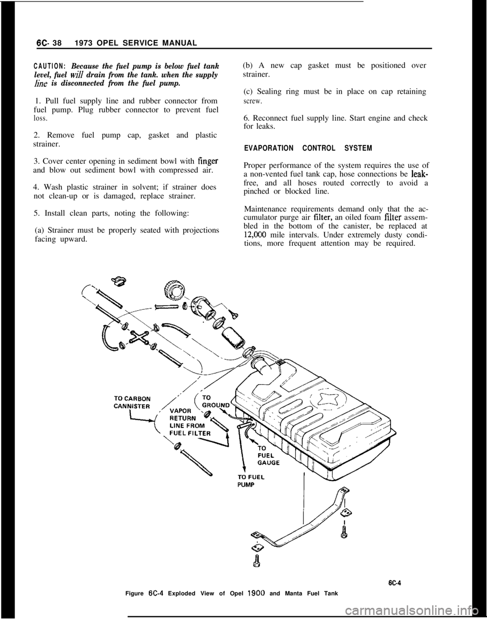
EVAPORATION CONTROL SYSTEMProper performance of the system requires the use of
a non-vented fuel tank cap, hose connections be leak-
free, and all hoses routed correctly to avoid a
pinched or blocked line.
Maintenance requirements demand only that the ac-
cumulator purge air tilter, an oiled foam filter assem-
bled in the bottom of the canister, be replaced at
12,CKO mile intervals. Under extremely dusty condi-
tions, more frequent attention may be required.
Figure
W-4 Exploded View of Opel 1900 and Manta Fuel Tank
Page 354 of 625
EMISSION CONTROL SYSTEMS6F- 63
2. With the engine “OFF”, observe damper doorposition through snorkel opening. If position of snor-kel makes observation difficult “se the aid of a mir-
ror. At this point damper door should be in such a
position that the heat stove passage is covered (snor-
kel passage open). If not, check for binds in linkage.3. Apply at least nine in. Hg. of vacuum to dia-
phragm assembly through hose disconnected at sen-
sor “nit. This can be done by mouth. Damper door
should completely close snorkel passage whenvacuum is applied. If not, check to see if linkage is
hooked up correctly and for a vacuum leak.
4. With vacuum applied, bend or clamp hose to trapvacuum in diaphragm assembly. Damper door
should remain in position (closed snorkel passage). Ifit does not, there is a vacuum leak in diaphragm
assembly. Replace diaphragm assembly.
Sensor Check
Quick Check of System:
1. Start test with engine cold, air cleaner at a temper-ature below 85 degrees. If the engine has been in
recent “se, allow it to cool.
2. Observe the air door before starting the engine: it
should be closed.3. Start the engine and allow it to idle. Immediately
after starting the engine, the air door should open.
4. As the engine warms up, the air door should start
to close, and the air cleaner should become warm tothe hand.
5. The system is operating normally as described
above. If the air cleaner fails to operate as above or
if correct operation of the air cleaner is still in doubt,
proceed to the thermometer check.
Thermometer Check of Sensor:1. Start test with air cleaner temperature below 85
degrees. IF ENGINE HAS BEEN RUN RE-
CENTLY, ALLOW IT TO COOL DOWN. Whileengine is cooling, remove air cleaner cover and in-
stall a temperature gage such as J- 22973 as close as
possible to
se&r. Keinstall air cleaner cover. Let car
stand idle for
l/2 hour or more before proceeding to
step 2.2. Start the engine. Air door should open immedi-
ately if engine is cool enough. When air door starts
to close (in a few minutes), remove air cleaner cover
and read temperature gage. It must
read 115 degreesplus or minus 20 degrees.
3. If air door does not start to close at temperatureindicated, temperature sensor is defective and must
be replaced.
EXHAUST GAS RECIRCULATION SYSTEM
TestingThe exhaust gas recirculation valve is to be checked
at 12,000 mile intervals “sing the following proce-
dure:1. With engine at operating temperature, connect a
tachometer to engine and note R.P.M. at idle.
2. Disconnect vacuum hose at the intake manifold
that goes to the air cleaner.
3. Disconnect vacuum hose for exhaust gas recircula-tion valve from the throttle valve and connect it to
the intake manifold where vacuum hose to air
cleaner was connected.4. Engine speed should decrease between
100-240R.P.M. from previously noted R.P.M.
5. If the R.P.M. decrease is less than 100 R.P.M., theexhaust gas recirculation valve and fitting going into
the intake manifold must be removed, cleaned, and’
reinstalled.
MAINTENANCE AND ADJUSTMENTS
EXHAUST GAS RECIRCULATION SYSTEM
CleaningClean the exhaust gas recirculation valve and fitting
with a piece of stiff wire removing all exhaust depos-
its.
CAUTION:Do not soak in solvent. After
r.einstafIing the valve and fitting, check op
eration as outlined under “Testing”. If
vahe does not operate properly after a
thorough cleaning, replace it.
MAJOR REPAIR
REMOVAL AND REPLACEMENT OECS UNITSThe damper door is not serviceable. The air cleaner
assembly must be replaced if the damper door is
defective.
R And R Vacuum Motor
1. Remove vacuum
motor retainer spring. See Figure
6F-5.
Page 405 of 625
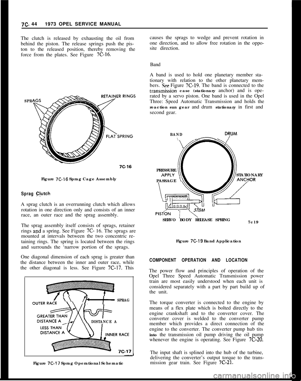
causes the sprags to wedge and prevent rotation in
one direction, and to allow free rotation in the oppo-
site direction.7C. 441973 OPEL SERVICE MANUAL
The clutch is released by exhausting the oil from
behind the piston. The release springs push the pis-
ton to the released position, thereby removing the
force from the plates. See Figure 7C-16.Band
A band is used to hold one planetary member sta-
tionary with relation to the other planetary mem-
bers.
!See Figure 7C-19. The band is connected to the
SPR
7C-16Figure
7C-16 Sprag Cage Assembly
Sprag C(utchA sprag clutch is an overrunning clutch which allows
rotation in one direction only and consists of an inner
race, an outer race and the sprag assembly.
The sprag assembly itself consists of sprags, retainer
rings and a spring. See Figure 7C- 16. The sprags are
mounted at intervals between the two concentric re-
taining rings. The spring is located between the rings
and surrounds the ‘narrow portion of the sprags.
One diagonal dimension of each sprag is greater than
the distance between the inner and outer race, while
the other diagonal is less. See Figure
7C-17. This
\ \I’b+ SPRAG
DISTANCE AFigure
7C-17 Sprag Operational Schematictransmissio; case (stationary anchor) and is ope-
rated by a servo piston. One band is used in the Opel
Three: Speed Automatic Transmission and holds the
reaction sun gear and drum stationary in first and
second gear.
BAND\- D7uM
PRESSURE
STATIONARY
PASSAGE
yPlSfON
1 y””SERVO BODY RELEASE SPRING
7c19
Figure
7C-19 Band Application
COMPONENT OPERATION AND LOCATIONThe power flow and principles of operation of the
Opel Three Speed Automatic Transmission power
train are most easily understood when each unit is
considered separately with a part by part build up of
the unit.
The torque converter is connected to the engine by
means of a flex plate which is bolted directly to the
engine crankshaft and to the converter cover. The
converter cover is welded to the converter pump
member which provides a direct connection of the
engine to the converter. The converter pump hub tits
into the transmission oil pump driving the oil pump
whenever the engine is operating. See Figure
7C-20.The input shaft is splined into the hub of the turbine,
delivering the converter’s output torque to the trans-
mission gear train. See Figure
7C-21.
Page 623 of 625

SubjectPage Number
Subject Page Number
o,,e, 1900 & Manta .....................1H-59
GT..................................lH-63
intake Manifold, 1.9L Engine
..........:.....6A-12
R
Radiator
JRadiator All Models .,.
Radio
66-32
Joint,
Ball
adder.; ...............................3A-7
dower...............................3A-7
K
Antenna Trimmer Adjustment GT
Antenna Trimmer Adjustment
Opel 1900
& Manta
Removal and Installation Opel 1900
& Manta
Removal and Installation GT
Trouble Diagnosis GT
.,.
Trouble Diagnosis -Opel 1900 &Manta
Reverse Clutch
Rings, Piston,
1.9L Engine
Rocker Arm Assembly.
1.9L Engine..
9C-1 06
9C-1 10
Keys and Locks ..........................OA-1
L
Low Servo Cover .........................7c-100
Lubrication
Engine Oil Change Interval ................OC-7
Oil Viscosity Chart. .....................
OC-7
Fluid Capacities........................OC-5
Lubrication System, Engine .................6A-4
9C-1 11
9c-107
9c-105
9c-109
7c-103
6A-19
6A-12
s
M
Mainshaft Assembly 4.Speed
Manual Transmission ....................
78-26
Manifold
Intake ...............................
6A-12
Exhaust ..............................
6A-12
Master
Cdlinder, Brake.....................5A-2
Model
D&ignation (Body Style)
.............. OA-2
Mountings. Engine, GT ....................
28-6
Opel 1900 & Manta
.......................28-6
0
Oil Chan& Interval ........................OC-7
Oil Filter: Engine
.........................OC-7
Oil Flow Circuits, Automatic Transmission .....7C-64
Oil
Pan. Engine ..........................6A-10
Oil Pump Engine.........................
6A-26
Oil Pump Transmission ....................
7C-103
Oil Recommendations Engine. ..............
OC-7
Oil Strainer-Transmission..................7C-99
Oil Viscosity Chart ........................
OC-7
Opel Emission Control System
(OECS)
Specifications..........................6F-64
Service Procedures......................6F-63
Trouble Diagnosis ......................
6F-62
P
Parking Brake............................5C-33
Piston, Pin Rings ..........................
6A~lS
Planetary Gear Set ........................
7C-118
Power Unit Brake ........................
5A-5
Propeller Shaft ...........................
4A-2
Pump, Oil Engine........................
6A-26 Sequence for Transmission Diagnosis
..........
7C-81
Service ProceduresClutch..................7A~5
Shift Linkage Adjustments
4.Speed Manual ........................78-19
3.Speed Automatic .....................7C~93
Shock Absorber, Rear
All Series .............................
3F-51
Spark Plug Specifications ...........................
66-68
Clean &Adjust. ........................
lC-22
Installation............................lC-22
Wires................................lC~21
Specifications
Engine ................................
6A-27
Front Wheel Alignment ....................
3C~22
Speedometer Installation
Opel1900&Manta.....................1 l-68
GT..................................11-70
Spring
Rear SuspensionAll Series ..............
:............3F-52
Front Suspension
Opel 1900
& Manta ...................3A~l6
GTO Opel ..........................
3A15
Starting Motor
Description ............................
1 E-1 0
Specifications .............:............1 B-1 7
Repairs
..................:............18-13
Removal..............................1 B-l 3
Steering Columns
Service Procedures -Opel 1900 &Manta ....
3E-36
Service Procedures
- GT ...._............3E-44
Steering Gear Adjustment. .....
:............3D-27
Steering Gear Disassembly and
Redssembly.....3D-30
Steering Gear Removal and Install&ion ........
30-28
Steering Linkage ..........................
38-19
Suspension
Front................................3A-2
Rear .................................
3F-51
,