adding oil OPEL GT-R 1973 Service Manual
[x] Cancel search | Manufacturer: OPEL, Model Year: 1973, Model line: GT-R, Model: OPEL GT-R 1973Pages: 625, PDF Size: 17.22 MB
Page 16 of 625
LUBRICATION AND MAINTENANCE OC-7SERVICESLUBE AND GENERAL MAINTENANCE
Vehicle operation under conditions such as heavy
dust, continuous short trips, use of other than un-
leaded or low lead fuels or pulling trailers, is not
considered normal use and therefore more frequent
maintenance will be required. Such additional
maintenance requirements are included where appli-
cable.
Engine OilChange each 4 months or
3,COO miles, whichever
occurs first, or each 2 months or
3,ooO miles when
the vehicle is operated under the following condi-
tions: (a) driving in dusty conditions, (b) trailer pull-
ing, (c) extensive idling or (d) short-trip operation at
freezing temperatures (with engine not thoroughly
warmed-up).Engine oils have a definite effect on ease of starting,
oil economy, combustion chamber deposits and en-
gine wear. It is recommended that a” oil which,
according to the label on the can is; (1) intended for
service SE and (2) passes car makers’ tests be used.
Oils confotming to these types contain detergent ad-
ditives. -
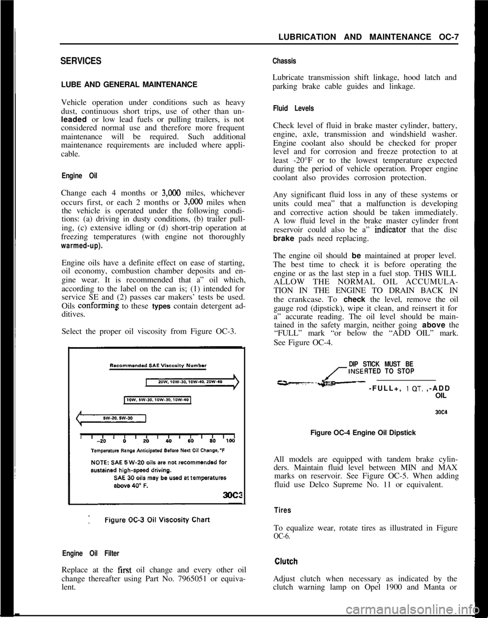
Select the proper oil viscosity from Figure OC-3.
Engine Oil FilterReplace at the first oil change and every other oil
change thereafter using Part No. 7965051 or equiva-
lent.
ChassisLubricate transmission shift linkage, hood latch and
parking brake cable guides and linkage.
Fluid LevelsCheck level of fluid in brake master cylinder, battery,
engine, axle, transmission and windshield washer.
Engine coolant also should be checked for proper
level and for corrosion and freeze protection to at
least -20°F or to the lowest temperature expected
during the period of vehicle operation. Proper engine
coolant also provides corrosion protection.
Any significant fluid loss in any of these systems or
units could mea” that a malfunction is developing
and corrective action should be taken immediately.
A low fluid level in the brake master cylinder front
reservoir could also be a” indtcator that the disc
brake pads need replacing.
The engine oil should be maintained at proper level.
The best time to check it is before operating the
engine or as the last step in a fuel stop. THIS WILL
ALLOW THE NORMAL OIL ACCUMULA-
TION IN THE ENGINE TO DRAIN BACK IN
the crankcase. To check the level, remove the oil
gauge rod (dipstick), wipe it clean, and reinsert it for
a” accurate reading. The oil level should be main-
tained in the safety margin, neither going above the
“FULL” mark “or below the “ADD OIL” mark.
See Figure OC-4.
DIP STICK MUST BE
INSERTED TO STOP
---L- -FULL+, 1 OT. ,-ADD
OIL
Figure OC-4 Engine Oil Dipstick
All models are equipped with tandem brake cylin-
ders. Maintain fluid level between MIN and MAX
marks on reservoir. See Figure OC-5. When adding
fluid use Delco Supreme No. 11 or equivalent.
TiresTo equalize wear, rotate tires as illustrated in Figure
OC-6.Adjust clutch when necessary as indicated by the
clutch warning lamp on Opel 1900 and Manta or
Page 324 of 625

COOLING SYSTEM6B- 33
remove drain plug on right.side of cylinder block. Set
heater temperature control valve at full heat posi-
tion. After the cooling system is drained, and plugs
reinstalled, fill the system with clean water. Run the
engine long enough to open the thermostat for com-
plete circulation through the system, then com-
pletely drain the cooling system before sediment has
a chance to settle.
Conditioning the Cooling System
“Rust Inhibitor and Stop Leak”, or equivalent listed
under Group 8.800 is recommended for use in the
cooling system, particularly when preparing for in-
stallation of anti-freeze solution. This material stops
small seepage leaks, has rust preventive properties
and its soluble oil is effective in eliminating a squeal-
ing noise which sometimes develops at the water
pump seal washer. Instructions for its application are
printed on the conditioner bottle.
It is very important to make certain that the cooling
system is properly prepared before an anti-freeze so-
lution is installed, otherwise loss of solution through
leakage may occur or seepage may result in damage
to the engine. The cooling system should be drained
and flushed as described under Draining and Flush-
ing Cooling System. All joints should be checked for
leakage and corrected, and the conditioner described
above should be added with the anti-freeze solution.
Inspect the water pump, radiator core, heater and
defroster cores, water jacket plugs, and edge of cylin-
der head gaskets for evidence of water leaks. Tighten
all hose clamps in the cooling and heating systems
and replace any deteriorated hoses.
Using and Testing Anti-Freeze
Solutions
Inhibited year around (ethylene glycol type) engine
coolant solution which is formulated to withstand
two full calendar years of normal operation without
draining or adding inhibitors should be used at all
times. Freeze protection should be provided to pro-
tect against corrosion. When adding solution due to
loss of coolant for any reason or in areas where tem-
peratures lower than minus 20 degrees F. may be
encountered, a sufficient amount of any of the sev-
eral brands of year around coolant (Ethylene Glycol
base) compatible to GM Specification 1899-M avail-
able on the market should be used. Water or alcohol
base coolants are not recommended for this vehicle
at any time.
If for any reason water only is used as a coolant in
an emergency, it is extremely important that Buick
Heavy Duty Cooling System Protector and Water
Pump Lubricant or equivalent be added to the cool-
ing system as soon as possible. If any other cooling
System protector is used, be certain it is labeled toindicate that it meets General Motors Specification
GM 1894-M. It should be recognized that this is only
a temporary measure. The manufacture intends that
permanent type coolant solution be used year around
in the cooling system.
The cooling system should be completely drained
and the recommended coolant installed every two (2)years.It is advisable to test the anti-freeze solution at inter-
vals during the winter to make certain that the solu-
tion has not been weakened. Use only hydrometers
which are calibrated to read both the specific gravity
and the temperature, and have a table or other means
of converting the freezing point at various tempera-
tures of solution. Disregarding the temperature of
the solution when making the test may cause an error
as large as 30 degrees F. Care must be exercised to
use the correct float or table for the particular type
of anti-freeze being tested.
Fan Belt Adjustment or Replacement
A tight fan belt will cause rapid wear of the alterna-
tor and water pump bearings. A loose belt will slip
and wear excessively and will cause noise, engine
over-heating, and unsteady alternator output. A fan
belt which is cracked or frayed, or which is worn so
that it bottoms in the pulleys should be replaced. The
fan belt may be replaced by loosening the alternator
brace at alternator, slightly loosening the alternator
mounting bolts and moving alternator inward to pro-
vide maximum slack in the belt.
The alternator must be moved outward to adjust the
fan belt. After the generator brace and mounting
bolts are securely tightened, the fan belt tension
should be 45 lb. using Tensioner J-23600.
WARNING: Zfa
fan blade is bent or damaged in any
way, no attempt should be made to repair and reuse
the damaged part. A bent or damaged fan assembly
should always be replaced with a new
fal. assembly.
It is essential that fan assemblies remain in proper
balance and proper balance cannot be assured once
a fan assembly has been bent or damaged. A fan
assembly that is not in proper balance could fail and
fly apart during subsequent
we creating an ex-
tremely dangerous condition.
Radiator Thermostat Inspection and Test
A sticking radiator thermostat will prevent the cool-
ing system from functioning properly. If the thermo-
stat sticks in the open position, the engine will warm
up very slowly. If the thermostat sticks in the closed
position, the engine will overheat.
The thermostat may be removed for inspection and
Page 325 of 625

6B- 341973 OPEL SERVICE MANUAL
test by partially draining the cooling system and dis-
connecting the water outlet housing from the ther-
mostat housing which is mounted on the right front
side of cylinder head.
The standard thermostat valve should start to open
at 189 degrees F and fully open at approximately 212
degrees F. If thermostat does not operate at specified
temperatures, it should be replaced as it cannot be
repaired.MAJOR REPAIR
WATER PUMP REPAIRSThe water pump bearing outer race is shrunk fit into
the water pump cover. For this reason the cover,
shaft bearing, and hub are not repairable.
Water Pump RemovalOpel radiators do not have a drain plug. Drain radia-
tor by first, loosening radiator cap, then remove
lower hose from lower radiator tank.
1. Drain coolant into a clean container. Remove
radiator and shroud.
2. Remove fan belt.
3. Remove fan blade and pulley on water pump shaft.
4. Disconnect inlet hose and heater hose from water
pump. Remove bolts, pump assembly and gasket
from timing chain cover.
5. Check pump shaft bearing for end play or rough-
ness in operation. If bearings are not in serviceable
condition, the assembly must be replaced.
Water Pump Installation1. Make sure the gasket surfaces on pump and timing
chain covers are clean. Install pump assembly with
new gasket. Bolts must be tightened uniformly.
Torque to 11 lb. ft.
2. Install radiator and shroud. Connect radiator hose
to pump inlet and heater hose to nipple.
3. Install fan pulley and fan blade, tighten attaching
bolts securely. Install belts and adjust for proper
tension.4. Fill cooling system and check
,for leaks at pump
and hose joints.
RADIATOR REMOVAL AND INSTALLATION
RemovalI. Loosen radiator cap, then remove lower radiator
hose and drain radiator coolant into suitable con-
tainer.
2. On vehicles with automatic transmission, unscrew
oil lines from connectors on lower radiator tank and
plug lines. On GT models with automatic transmis-
sion the lines have to be disconnected at the coupling
before removing from the tank. It is essential that no
dirt enters the oil lines. When unscrewing oil lines,
hold connectors on lower radiator tank with pliers to
avoid leakages. Ensure that no dirt enters oil cooler.
3. Remove lower attaching nut and slide radiator
upward and out of engine compartment.
Installation1. Install radiat,or into engine compartment and se-
cure lower attaching nut.
2. On vehicles with automatic transmissions, fasten
oil cooler lines to lower radiator tank. It is essential
that no dirt enters the oil lines. When tightening oil
lines, hold connectors on lower radiator tank with
pliers to avoid leakages. Ensure that no dirt enters oil
cooler. Torque to 1 I-15
lbs.ft.3. Install lower radiator hose and add collected coo-
lant.
All Opels are provided with a radiator initial fill of
an antifreeze solution containing corrosion inhibitor.
The antifreeze has either a glycol or glycerin base
and protects the engine against freezing, down to
minus 22 degrees F. (minus 30 degrees C.). Before
the start of the cold season, coolant must be checked
with a hydrometer and if necessary, brought to the
necessary specific gravity by adding anti-freeze with
a glycol or glycerin base. As the specific gravities of
all anti- freeze solutions having a glycol or glycerin
base are practically the same, the hydrometer can be
used for all these types. Because of the tolerances of
the hydrometer, or slight differences in specific
gravity, variations of plus or minus 5 degrees can be
expected. Coolant must be checked at a temperature
of plus 68 degrees F. (plus 20 degrees C.)
Page 399 of 625
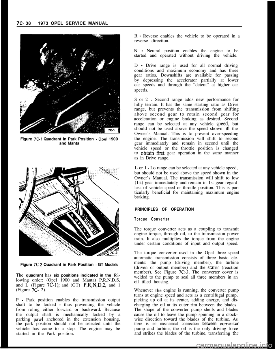
Figure 7C-1 Quadrant In Park Position -Opel 1900
and Manta7C- 381973 OPEL SERVICE MANUAL
R
- Reverse enables the vehicle to be operated in a
reverse direction.
N
- Neutral position enables the engine to be
started and operated without driving the vehicle.
D
- Drive range is used for all normal driving
conditions and maximum economy and has three
gear ratios. Downshifts are available for passing
by depressing the accelerator partially at lower
car speeds and through the “detent” at higher car
speeds.
S or 2
- Second range adds new performance for
hilly terrain. It has the same starting ratio as Drive
range, but prevents the transmission from shifting
above second gear to retain second gear for
acceleration or engine braking as desired. Second
range can be selected at any vehicle speed, but
should not be used above the speed shown m the
Owner’s Manual. This is to prevent over-speeding
the engine. The transmission will shift to second
gear immediately and remain in second until the
vehicle speed or the throttle position is changed
to obtajn first gear operation in the same manner
as in Drive range.
L or 1
- Lo range can be selected at any vehicle speed,
but should not be used above the speed shown in the
Owner’s Manual. The transmission will shift to low
(1st) gear immediately and remain in 1st gear regard-
less of vehicle speed or throttle position. This is par-
ticularly beneficial for maintaining maximum engine
braking.
PRINCIPLES OF OPERATION
Torque ConverterThe torque converter acts as a coupling to transmit
engine torque, through oil, to the transmission power
train. It also multiplies the torque from the engine
under certain conditions of input and output speed.
Figure
7C-2 Quadrant in Park Position - GT Models
The quadrant has six positions indicated in the fol-
lowing order: (Opel 1900 and Manta) P,R,N,D,S,
and L (Figure
7C-1); and (GT) P,R,N,D,2, and 1
(Figure 7C- 2).The torque converter used in the Opel three speed
automatic transmission consists of three basic ele-
ments: the pump (driving member), the turbine
(driven or output member) and the stator (reaction
member). See Figure
7C-3. The converter cover is
welded to the pump to seal all three members in an
oil tilled housing.
P
- Park position enables the transmission output
shaft to be locked
- thus preventing the vehicle
from roling either forward or backward. Because
the output shaft is mechanically locked by a
parking
paw1 anchored in the extension housing,
the park position should not be selected until the
vehicle has come to a stop. The engine may be
started in the Park position.Whenever the engine is running, the converter pump
turns at engine speed and acts as a centrifugal pump,
picking up oil at its center, adding energy, and dis-
charging the oil at its outer rim between the blades.
The shape of the converter pump shells and blades
cause the oil to leave the pump spinning in a clock-
wise direction toward the blades of the turbine. Asthere is no mechanical connection between converterpump and turbine, the oil is the only driving force
and strikes the blades of the turbine, transferring the
Page 495 of 625
7C-1341973 OPEL SERVICE MANUAL
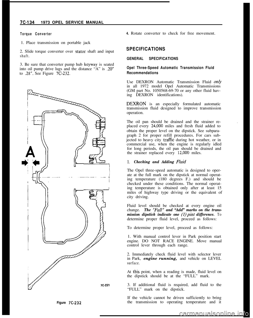
Figure 7C-232
Torque Converter4. Rotate converter to check for free movement.
1. Place transmission on portable jack
2. Slide torque converter over stator shaft and input
shaft.3. Be sure that converter pump hub keyway is seated
into oil pump drive lugs and the distance “A” is
.20”to
.28”. See Figure 7C-232.
SPECIFICATIONS
GENERAL SPECIFICATIONS
Opel Three-Speed Automatic Transmission Fluid
RecommendationsUse DEXRON Automatic Transmission Fluid on/y
in all 1972 model Opel Automatic Transmissions
(GM part No. 1050568-69-70 or any other fluid hav-
ing DEXRON identifications).DEXIRON is an especially formulated automatic
transmission fluid designed to improve transmission
operation.
The oil pan should be drained and the strainer re-
placed every
24,ooO miles and fresh fluid added to
obtain the proper level on the dipstick. See subpara-
graph 2 for proper refill procedures. For cars sub-
jected to heavy city
traff%z during hot weather, or in
commercial use, when the engine is regularly idled
for long periods, the oil pan should be drained and
the strainer replaced every
12,ooO miles.
.
1.Checking and Adding FluidThe Opel three-speed automatic is designed to oper-
ate at the full mark on the dipstick at normal operat-
ing temperature (180 degrees F.) and should be
checked under these conditions. The normal operat-
ing temperature is obtained only after at least 15
miles of highway type driving or the equivalent of
city driving.
Fluid level should be checked at every engine oil
change.
The “FuIl” and “Add” marks on the trans-
mission dipstick indicate one (1)pint
difference. Todetermine proper fluid level, proceed as follows:
To determine proper level, proceed as follows:
1. With manual control lever in Park position start
engine. DO NOT RACE ENGINE. Move manual
control lever through each range.
2. Immediately check fluid level with selector lever
in Park, engine running, and vehicle on LEVEL
surface.At
t,his point, when a reading is made, fluid level on
the dipstick should be at the “FULL” mark.
3. If additional fluid is required, add fluid to the
“FULL” mark on the dipstick.
If the vehicle cannot be driven sufficiently to bring
the transmission to operating temperature and it
Page 496 of 625
AUTOMATIC TRANSMISSION 7C-135
becomes necessary to check the fluid level, the trans-
mission may be checked at room temperature (70
degrees F.) as follows:
1. With manual control lever in Park position start
engine. DO NOT RACE ENGINE. Move manual
control lever through each range.
2. lmmediately check fluid level with selector lever
in Park, engine running, and vehicle on LEVEL sur-
face.At this point, when a reading is made, fluid level on
the dipstick should be I/4” below the “ADD” mark.
3. If additional fluid is required add fluid to bring
level to
l/4” below the “ADD” mark on the dip-
stick.If transmission fluid level is correctly established at
70 degrees F. it will appear at the “FULL” mark on
the dipstick when the transmission reaches normal
operating temperature (180 degrees F.) The fluid
level is set
l/4” below the “ADD” mark on the
dipstick to allow for expansion of the fluid which
occurs as transmission temperatures rise to normal
operating temperature of 180 degrees F.
Do not overfill, as foaming and loss of fluid through
the vent pipe might occur as fluid heats up. If fluid
is too low especially when cold, complete loss
of’drive may result which can cause transmission fail-
ure.
2.Draining oilpan and rep/a&g strainer assembly.
(a) Raise car on hoist or p/ace OnJxk stands, and
provide container to collect draining fluid.
(b) Remove oil pan and gasket. Discard gasket.
(c) Drain fluid from oil pan. Clean pan with solvent
and dry thoroughly with clean compressed air.
(d) Remove strainer assembly, strainer gasket and
discard.
(e) Install new oil strainer gasket. Install new strainer
assembly.
(f) Install new gasket on oil pan and install pan.
Tighten attaching bolts to 7-10 lb. ft.
(g) Lower car and add approximately three (3) pints
of transmission fluid through filler tube.
(h) With manual control lever in Park position, start
engine. DO NOT RACE ENGINE. Move manual
control lever through each range.
(i) Immediately check fluid level with selector leverin Park, engine running, and vehicle on LEVEL
sur-
face.(i) Add additional fluid to bring level to
l/4” below
the “ADD” mark on the dipstick. Do not overfill.
3.Adding Fluid to Fill Dry Transmission and Con-
verter Assembly
The fluid capacity of the Opel Three Speed Auto-
matic transmission and converter assembly is ap-
proximately IO-l/2 pints, but correct level is
determined by the mark on the dipstick rather than
by amount added. In cases of transmission overhaul,
when a complete fill is required, including a new
converter proceed as follows:
(a) Add approximately 10-l/2 pints of transmission
fluid through tiller tube.
The converter should be replaced on any major fail-
ure, such as a clutch or gearset, and an excessive
amount of foreign material is indicated in the pan. If
installation of a new converter is not required add
approximately five (5) pints of transmission fluid.
(b) With manual control lever in Park position start
engine and run at 1000 RPM. DO NOT RACE EN-
GINE. Move manual control lever through each
range.
(c) Immediately check fluid level with selector lever
in Park, engine running, and vehicle on LEVEL
sur-
face.(d) Add additional fluid to bring level to
l/4” below
the “ADD” mark on the dipstick. Do not overfill.
Opel Three Speed Automatic Transmission Towing
Instructions
If an Opel equipped with an automatic transmission
must be towed, the following precautions must be
observed:
The car may be towed safely on its rear wheels with
the shift lever in neutral position at speeds of 35 miles
per hour or less under most conditions.
However, the drive shaft must be disconnected or the
car towed on its front wheels if:
a. Tow speeds in excess of 35 mph are necessary.
b. Car must be towed for extended distances (over 50
miles).
c. Transmission is not operating properly.
If car is towed on its front wheels, the steering wheel
Page 526 of 625

REFRIGERANT COMPONENTS
ALL MODELS
CONTENTS
Subject
DESCRIPTION AND OPERATION:
FundamentalPrinciplesofRefrigeration..................
Description of Air Conditioning Components
..........DIAGNOSIS:
GeneralInformation..........................................................
Leak Testing
System1........................................................
Functional Testing System............................................
DiagnosisGuide..................................................................
MAINTENANCE AND ADJUSTMENTS:
General Service Information and
Safety Precautions;........................................................
Charging
andDischargingSystem..............................
AddingOiltotheSystem................................................
Flushing the System........................................................
MAJOR REPAIR:
Removal and Installation Compressor
Opel1900.Manta........................................................
GT
........................................................................................
Removal and Installation Condenser
Receiver-Dehydrator
Assembly
- GT.................................................................
Receiver-Dehydrator
.Opel 1900.Manta................GT..................................................
Removal and Installation Evaporator and
Expansion Valve
- Opel 1900.Manta....................
GT......................................................
Disassembly and Reassembly of Clutch Drive
Plate
andShaftSeal....................................................
Disassembly and Reassembly of Pulley Assembly
and Coil and Housing Assembly..............................
Disassembly and
Reaissembly of Internal
Parts of Compressor and Leak Testing
Compressor..............................................................................
SPECIFICATIONS:
Specifications........................................................................Page No.
9B-18
98-33
98-38
98-39
98-39
90-40
98-41
98-41
9B-47
98-48
98-48
98-56
98-62
90-4990-58
98-52
98-59
98-63
98-67
98-69
98-82REFRIGERANT COMPONENTS ALL MODELS
96-17
Page 531 of 625
9B-22 1973 OPEL SERVICE MANUAL
We can change a vapor back into a liquid by chilling
it, or do the same thing with pressure. When we
condense a vapor we will find that the heat removed
just exactly equals the amount of heat that was neces-
sary to make the substance vaporize in the first place.
At last the lost is found! The latent heat of vaporiza-
tion the heat that apparently disappeared when
a liquid boiled into a vapor again reappears on
the scene when that same vapor reverts back into a
liquid. It is just like putting air into a balloon to
expand it and then letting the same amount of air out
again to return the balloon to its original condition.
We know that any substance will condense at the
same temperature at which it boiled. This tempera-
ture point is a clear-cut division like a fence. On one
side, a substance is a liquid. Immediately on the
other side it is a vapor. Whichever way a substance
would go, from hot to cold or cold to hot, it will
change its character the moment it crosses over thefence.But pressure moves the fence! Water will boil at 212
degrees under normal conditions. Naturally, we ex-
pect steam to condense at the same temperature. But
whenever we put pressure on steam, it doesn’t! It will
condense at some temperature higher than 212 de-
grees. The greater the pressure, the higher the boiling
point and the temperature at which a vapor will
condense. This is the reason why pressure cookers
cook food faster, since the pressure on the water
permits it to boil out at a higher temperature. We
know that R-12 boils at 21.7 degrees below zero. A
thermometer will show us that the rising vapors,
even though they have soaked up lots of heat, are
only slightly warmer. But the vapors must be made
warmer than the room air if we expect heat to flow
out of them. Also, the condensing point temperature
must be above that of room air or else the vapors
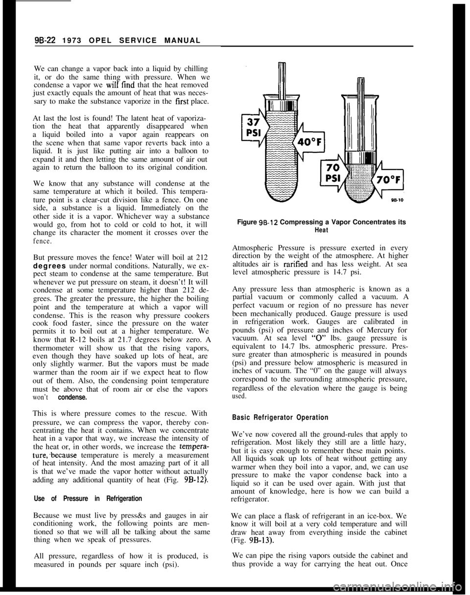
won’t condense.This is where pressure comes to the rescue. With
pressure, we can compress the vapor, thereby con-
centrating the heat it contains. When we concentrate
heat in a vapor that way, we increase the intensity of
the heat or, in other words, we increase the tempera-ture;because temperature is merely a measurement
of heat intensity. And the most amazing part of it all
is that we’ve made the vapor hotter without actually
adding any additional quantity of heat (Fig.
9B-12).
Use of Pressure in RefrigerationBecause we must live by press&s and gauges in air
conditioning work, the following points are men-
tioned so that we will all be talking about the same
thing when we speak of pressures.
All pressure, regardless of how it is produced, is
measured in pounds per square inch (psi).Figure 98.12 Compressing a Vapor Concentrates its
HeatAtmospheric Pressure is pressure exerted in every
direction by the weight of the atmosphere. At higher
altitudes air is raritied and has less weight. At sea
level atmospheric pressure is 14.7 psi.
Any pressure less than atmospheric is known as a
partial vacuum or commonly called a vacuum. A
perfect vacuum or region of no pressure has never
been mechanically produced. Gauge pressure is used
in refrigeration work. Gauges are calibrated in
pounds (psi) of pressure and inches of Mercury for
vacuum. At sea level
“0” lbs. gauge pressure is
equivalent to 14.7 lbs. atmospheric pressure. Pres-
sure greater than atmospheric is measured in pounds
(psi) and pressure below atmospheric is measured in
inches of vacuum. The “0” on the gauge will always
correspond to the surrounding atmospheric pressure,
regardless of the elevation where the gauge is being
used.
Basic Refrigerator OperationWe’ve now covered all the ground-rules that apply to
refrigeration. Most likely they still are a little hazy,
but it is easy enough to remember these main points.
All liquids soak up lots of heat without getting any
warmer when they boil into a vapor, and, we can use
pressure to make the vapor condense back into a
liquid so it can be used over again. With just that
amount of knowledge, here is how we can build a
refrigerator.
We can place a flask of refrigerant in an ice-box. We
know it will boil at a very cold temperature and will
draw heat away from everything inside the cabinet
(Fig. 9B-13).
We can pipe the rising vapors outside the cabinet and
thus provide a way for carrying the heat out. Once
Page 532 of 625
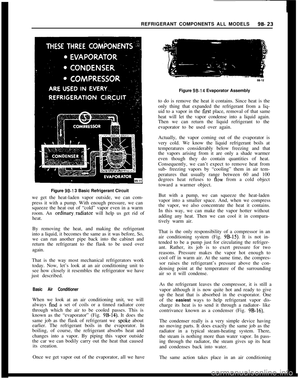
REFRIGERANT COMPONENTS ALL MODELS96.23Figure 96-l 3 Basic Refrigerant Circuit
we get the heat-laden vapor outside, we can com-
press it with a pump. With enough pressure, we can
squeeze the heat out of “cold” vapor even in a warm
room. An ordinary.radiator will help us get rid of
heat.
By removing the heat, and making the refrigerant
into a liquid, it becomes the same as it was before, So,
we can run another pipe back into the cabinet and
return the refrigerant to the flask to be used over
again.
That is the way most mechanical refrigerators work
today. Now, let’s look at an air conditioning unit to
see how closely it resembles the refrigerator we have
just described.
Basic Air ConditionerWhen we look at an air conditioning unit, we will
always find a set of coils or a tinned radiator core
through which the air to be cooled passes. This is
known as the “evaporator” (Fig.
9B-14). It does the
same job as the flask of refrigerant we
spok.e about
earlier. The refrigerant boils in the evaporator. In
boiling, of course, the refrigerant absorbs heat and
changes into a vapor. By piping this vapor outside
the car we can bodily carry out the heat that caused
its creation.
Once we get vapor out of the evaporator, all we haveFigure 98.14 Evaporator Assembly
to do is remove the heat it contains. Since heat is the
only thing that expanded the refrigerant from a liq-
uid to a vapor in the first place, removal of that same
heat will let the vapor condense into a liquid again.
Then we can return the liquid refrigerant to the
evaporator to be used over again.
Actually, the vapor coming out of the evaporator is
very cold. We know the liquid refrigerant boils at
temperatures considerably below freezing and that
the vapors arising from it are only a shade warmer
even though they do contain quantities of heat.
Consequently, we can’t expect to remove heat from
sub- freezing vapors by “cooling” them in air tem-
peratures that usually range between 60 and 100
degrees heat refuses to
flow from a cold object
toward a warmer object.
But with a pump, we can squeeze the heat-laden
vapor into a smaller space. And, when we compress
the vapor, we also concentrate the heat it contains.
In this way, we can make the vapor hotter without
adding any heat. Then we can cool it in compara-
tively warm air.
That is the only responsibility of a compressor in an
air conditioning system (Fig.
9B-15). It is not in-
tended to be a pump just for circulating the refriger-
ant. Rather, its job is to exert pressure for two
reasons. Pressure makes the vapor hot enough to
cool off in warm air. At the same time, the compres-
sor raises the refrigerant’s pressure above the con-
densing point at the temperature of the surrounding
air so it will condense.
As the refrigerant leaves the compressor, it is still a
vapor although it is now quite hot and ready to give
up the heat that is absorbed in the evaporator. One
of the easiest ways to help refrigerant vapor dis-
charge its heat is to send it through a radiator- like
contrivance known as a condenser (Fig. 9B-16).
The condenser really is a very simple device having
no moving parts. It does exactly the same job as the
radiator in a typical steam-heating system. There,
the steam is nothing more than water vapor. In pass-
ing through the radiator, the steam gives up its heat
and condenses back into water.
The same action takes place in an air conditioning
Page 539 of 625
9B-30 1973 OPEL SERVICE MANUAL
refrigerant penetrates to every nook and cranny of
the unit.
Among the many desirable properties of R-12, is its
stability under operating conditions. However, while
more stable than the other refrigerants under the
same conditions, it, too, can be caused to form harm-
ful acids which will eventually fail the system.OilOil is the most complex of all of the organic chemi-
cals. Its stability in a refrigerating system is depend-
ent upon the source of crude oil and its method of
refining. A good refrigerating oil must be free of
sludge and gum-forming substances and free of
harmful impurities, such as sulphur. It must also be
stabilized to resist oxidation and must have a high
degree of resistance to carbonization.
The chemical properties of the lubricating oil form
another very important consideration in the chemi-
cal stability within the system. Like the refrigerant,
it travels to every nook and cranny of the unit.
The factory obtains the finest oils which have been
refined from the most desirable
crudes. It is reproc-
essed at the factory before it is charged into a system
or poured into a container for resale. Its
voscosityand flash point are checked and it is forced through
many sheets of filtering paper.
Even the containers in which it is poured for resale
are processed. As you recive it for field service it is
the cleanest, dry&, and purest oil that is humanly
possible to make. Leaving the container uncapped
even for a few minutes allows the oil to absorb mois-
ture from the air. Many system failures have been
caused by chemical reactions which were started by
servicemen adding contaminated oil.
Desiccants (Dehydrating Agent)Over the years the industry has spent hundreds of
thousands of dollars in finding and developing
chemical substances which are suitable for use in
refrigerating systems. An ideal desiccant must have
the following characteristics:
I. High capacity.
2. High eficiency.
3. Low tendency to powder.
4. Absorb moisture without reacting chemically with
it.5. Allow refrigerant to flow through it with mini-
mum restriction.
6. Retain moisture at high temperature.This has been a difficult combination to find. While
some desiccants excel in several of the desirable char-
acteristics, they are unsatisfactor:y in others.
Activated Silica Alumina, used in current
receiver-dehydrators, is a most satisfactory desiccant. How-
ever, its ability to retain moisture is affected by its
temperature. As the temperature increases, its ability
decreases. This means that moisture which is re-
tained at a lower temperature may be put back into
the system at a higher temperature.
MAINTAINING CHEMICAL STABILITY IN THE
REFRIGERATION SYSTEMThe metal internal parts of the refrigeration system
and the refrigerant and oil contained in the system
are designed to remain in a state of chemical stability
as long as pure R-12 plus refrigeration oil is used in
the system. However, when abnormal amounts of
foreign materials, such as dirt, air or moisture are
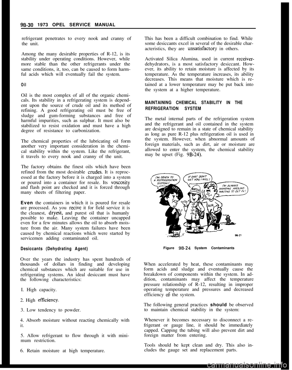
allowed to enter the system, the chemical stability
may be upset (Fig. 9B-24).
Figure
98.24 System Contaminants
When accelerated by heat, these contaminants may
form acids and sludge and eventually cause the
breakdown of components within the system. In ad-
dition, contaminants may affect the temperature
pressure relationship of R-12, resulting in improper
operating temperature and pressures and decreased
efficiency
OF the system.
The following general practices should be observed
to maintain chemical stability in the system:
Whenever it becomes necessary to disconnect a re-
frigerant or gauge line, it should be immediately
capped. Capping the tubing will also prevent dirt and
foreign matter from entering.
Tools should be kept clean and dry. This also in-
cludes the gauge set and replacement parts.