ignition OPEL GT-R 1973 Owner's Manual
[x] Cancel search | Manufacturer: OPEL, Model Year: 1973, Model line: GT-R, Model: OPEL GT-R 1973Pages: 625, PDF Size: 17.22 MB
Page 76 of 625

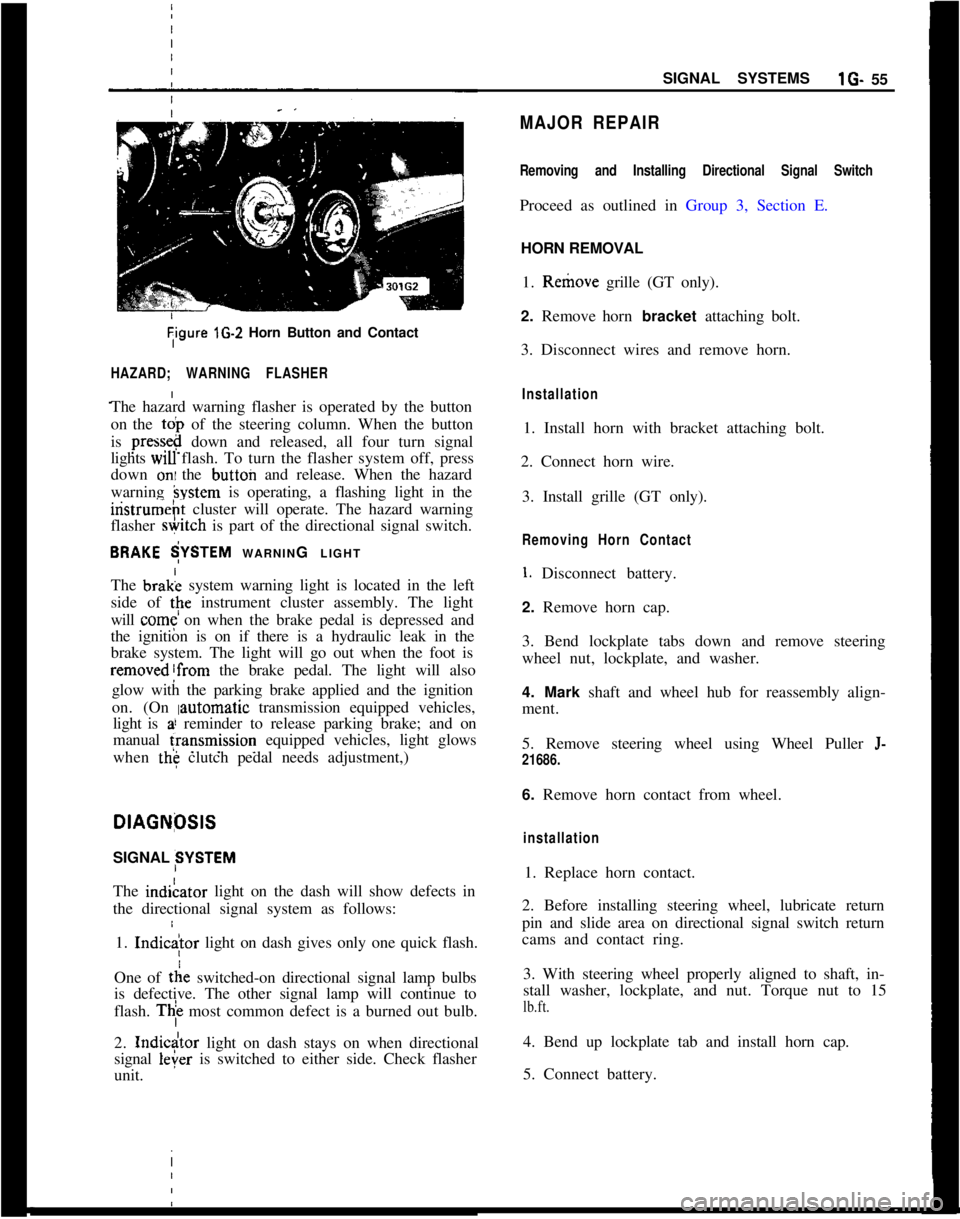
Tigure lG-2 Horn Button and Contact
HAZARD; WARNING FLASHER
The hazard warning flasher is operated by the button
on the
toi, of the steering column. When the button
is
press&@ down and released, all four turn signal
lights
WIU flash. To turn the flasher system off, press
down
oni the button and release. When the hazard
warning
hystem is operating, a flashing light in the
iristrumeht cluster will operate. The hazard warning
flasher
&itch is part of the directional signal switch.
BRAKE $YSTEM WARNING LIGHT
The brak; system warning light is located in the left
side of
tpe instrument cluster assembly. The light
will
come on when the brake pedal is depressed and
the ignition is on if there is a hydraulic leak in the
brake system. The light will go out when the foot is
removed!from the brake pedal. The light will also
glow with the parking brake applied and the ignition
on. (On
Iautomatic transmission equipped vehicles,
light is
a! reminder to release parking brake; and on
manual
fransmission equipped vehicles, light glows
when
the clutch pedal needs adjustment,)
I
DlAGNfXlS
SIGNAL SYSTEM
The indiLator light on the dash will show defects in
the directional signal system as follows:
1.
Indic
tie switched-on directional signal lamp bulbs
is defective. The other signal lamp will continue to
flash.
Thi most common defect is a burned out bulb.
2.
Indicdtor light on dash stays on when directional
signal
leier is switched to either side. Check flasher
unit. I
SIGNAL SYSTEMSlG- 55
MAJOR REPAIR
Removing and Installing Directional Signal Switch
Proceed as outlined in Group 3, Section E.
HORN REMOVAL
1. Remove grille (GT only).
2. Remove horn bracket attaching bolt.
3. Disconnect wires and remove horn.
Installation
1. Install horn with bracket attaching bolt.
2. Connect horn wire.
3. Install grille (GT only).
Removing Horn Contact
1. Disconnect battery.
2. Remove horn cap.
3. Bend lockplate tabs down and remove steering
wheel nut, lockplate, and washer.
4. Mark shaft and wheel hub for reassembly align-
ment.
5. Remove steering wheel using Wheel Puller
J-
21686.
6. Remove horn contact from wheel.
installation
1. Replace horn contact.
2. Before installing steering wheel, lubricate return
pin and slide area on directional signal switch return
cams and contact ring.
3. With steering wheel properly aligned to shaft, in-
stall washer, lockplate, and nut. Torque nut to 15
lb.ft.
4. Bend up lockplate tab and install horn cap.
5. Connect battery.
Page 77 of 625

:lG- 56 1973 OPEL SERVICE MANUAL
I
FUSEqOSlTlON
1
2
3
4
5
6AMPS.
5
5
8
15
15
8ClRClJlT$ PROTECTED
OPEL 1900
& ‘MANTA (51,53,54,57,57R)
LEFT PARkING LIGHT,
LEFTTAIL LIGHT, LEFTSIDE
MARKER LIGHTS
RIGHT PApKING LIGHT, RIGH TAIL LIGHT, RIGHT
SIDE MARKER LIGHTS, INSTRUMENT PANEL LIGHTS,
SHIFT GUADRANT LIGHTS, LICENSE PLATE LIGHT,
FOG LIGHTS (RALLYE ONLY)
IGNITION IKEY
WARNIN BUZZER, TRUNK LIGHT,
HAZARD WARNING FLA,SHER, COURTESY LIGHT, CLOCK
BACKUP L’IGHTS, BLOWER MOTOR, CIGAR LIGHTER; RADIO,
SAFETY BELT WARNING BUZZER AND LIGHT
WINDSHIELD WIPERS, WINDSHIELD WASHER (RALLYE
ONLY), HORN
STOP LIGtiTS,TURN
SlGsNAL AND INDICATOR LIGHT,
PARKING BRAKE WARNING AND BRAKE FAILURE LIGHT,
FUEL GAGE, TEMPERATURE GAGE, OIL PRESSUREINDICATGR LIGHT. CHARGING INDICATOR~LIGHT,
TACHOMETER AND OIL PRESSURE GAGE (RALLYE ONLY)
AIR CONDITIONING
- 20 AMP INLINE F:USE
8
5
16
5OPEL GT
(77)WINDSHIELD WIPERS, WINDSHIELD WASHER, HORN, BACKUP
LIGHT, SP;FETY BELT WARNING BUZZER AND LIGHT
STOP LIGHTS, TURN SIGNAL AND INDICATOR LIGHT,
PARKING BRAKE WARNING LIGHT (AUTOMATIC ONLY),
BRAKE FAILURE WARNING LIGHT, RADIO, TACHOMETER,
OIL PRESiURE GAGE
& INDICATOR LIGHT, FUEL GAGE,
TEMPERATURE GAGE, CHARGING INDICATOR LIGHT
CIGAR LIGHTER, BLOWER MOTORIGNITION~KEY WARNING BUZZER, COURTESY LIGHT, CLOCK,
HAZARD WARNING FLASHER
LEFT PARKING LIGHTS, LEFT TAIL LIGHT, LEFT REAR
SIDE MAdKER LIGHT
RIGHT PA’RKING LIGHTS, RIGHT TAIL LIGHT, RIGHT REAR
SIDE MAdKER LIGHT
INSTRUMENT PANEL LIGHTS, LICENSE PLATE LIGHT.
SHIFT QUADRANT LIGHT
AIR CON,DlTlONlNG
-A/C HAS A 20 AMP INLINE FUSE AND IS
CONNECTED TO THE HOTSIDE OF FUSE NO. 23OlG3
Page 78 of 625

,I
IINSTRUMENT PANEL
lH- 57
/
/SubjectPage No. INSTRUMENT PANEL
CONTENTS
DESCRIPTION AND OPERATION:
Instrument Panel
- Opel 1900 - Manta. . . . . . . . . . . . . . . . . . . . . .Instrument
Panel-GT. . . . . . . . . . . . . . . . . . . . . . . . . . . . . . . . . . . . . . . . . . . . . . . . . . . . . .DIAGNOSIS:
MAINTENANCE AND ADJUSTMENTS:
MAJOR REPAIR:
Instrument Cluster Housing
- Opel 1900 - Manta . .
Windshield Wiper Switch
. , . . . . . . . . . . . . . . . . . . . . . . . . . . . . . . . . . . . . . . . . . . . .InstrumentCluster
Bulbs. . . . . . . . . . . . . . . . . . . . . . . . . . . . . . . . . . . . . . . . . . . . . . . .InstrumentCluster
Housing-GT. . . . . . . . . . . . . . . . . . . . . . . . . . . . . . . . . .Combined Switch Assemblies
. . . . . , . . . . . . . . . . . . . . . . . . . . . . . . . . . . . . . .CigarLighter
. . . . . . . . . . . . . . . . . . . . . . . . . . . . . . . . . . . . . . . , . . . . . . . . . . . . . . . . . . . . . . . . . . . . . . . .SPECIFICATIONS: (Not Applicable)
I H-57
1H-58
1H-59
1H-61
lH-61
1H-61
1H-63
1H-64
DESCF(lPTlON AND OPERATION2. The fog light toggle switch lower half is pushed in.INSTRUFENT PANEL (OPEL 1900. MANTA)
Headligl$ Switch
3. The parking lights and/or low beam headlights are
on.The thr& position light switch controls the head-
lights, @lights, parking lights, side marker lights,
license
plate light and instrument panel lights and is
located
4t the lower left on the instrument panel.
With thk switch knob pulled outward to the first
stop,
thi parking lights, side marker lights, license
plate
ligiit and instrument panel lights will light. Theinstrumdnt panel lights can be turned off by turning
the
lightSwitch knob counterclockwise past the first
detent. IThe fog lights are automatically turned off if the
ignition switch is on and the headlights are on high
beam.
Windshield Wiper Switch
The windshield wiper switch is located on the instru-ment panel to the right of the headlight switch.
By pull&g the lightswitch knob out all the way, the
headlights will also be turned on.
IBy pushing the lower half of this switch in to the first
stop, the wipers will operate at slow speed. By push-ing in to the second stop, the wipers will operate at
fast speed.
Fog
Ligh) Switch (Rallye)The fog
iight toggle switch is located in the instru-
ment cluster to the left of the temperature and fuel
gauge
cl+ster. The fog lights can be turned off at any
time by
t,he toggle switch, but can only be turned on
when: ,
Electrically Heated Rear Window Switch (If
Equipped)The heated rear
wind&v switch is located in the
instrument panel to the right of the clock opening.
1. The ignition switch is on or the engine running.
ITo operate (only possible with the engine running),
push in on the lower half of the switch. When the
rear window is being heated, the switch will
belighted.
Page 80 of 625

/
I
IINSTRUMENT PANELlH- 59
Figure 1 H-2
- GT Instrument and Switch Arrangement
The Wihdshield Wipers have two-speed operation.
By pushing the lower half of the switch inward to the
first stop, the wipers will operate at half speed and
by deprbssing to the second stop will provide full
speed oieration. When the switch is returned to the
off posit/on, the wiper blades automatically return to
their park position.
I
The El
this optlpn. The engine must be running before
suffi-cient current can be generated to energize this circuit
even th6ugh the switch is depressed to the “ON”
position! When the window is being heated, a warm-
ing light’on the instrument panel will glow. This light
is locate? below the left ventilation inlet.
The
Heiter Blower Switch is a three position switch.
By depressing the lower half of the switch to the first
stop,
th& blower will operate at low speed. Whendepressdd to the second stop, the blower will operate
at high ipeed.
Four Way Hezrerd Warning Flasher SwitchThe
hazard warning flasher switch is located below
the heater controls in the center console. By
depress-ing the lower half of the switch, all four turn- signal
lamps flash at the same time. Although this system
makes use of the regulat turn signal system, it has a
separate feed wire to the switch which allows for its
operation even with the ignition switch and doors
locked. No vehicle should be driven with this system
in operation because of its universal meaning “This
Vehicle Is Not Moving”. To turn the system off,
simply depress the upper half of the switch.
MAJOR REPAIR
Removal of Instrument Cluster Housing Assembly.Opel 1900 Manta
Before starting any instrument panel repair, always
disconnect battery ground cable first.
I
Page 82 of 625

I
I
IINSTRUMENT PANELlH- 61Figwe 1 H-7
- Disconnecting Cluster Wires
4. Install instrument cluster trim plate and replace
two screw and plugs.
5. Con&t speed0 cable by turning coupling clock-
wise. 1
6. Install light
.switch button and heater control
knobs. I
I
7. Con+ct battery cable.
Removidg Windshield Wiper Switch - Opel 1900Manta I
1.
Rem* instrument cluster trim plate.
2. Corndress retaining clips and remove switch. See
Figure iH-8.
I
Figure lH-8 . Removing Windshield Wiper Switch3. Disconnect wiring connector.
Installation1. Connect wiring to switch.
2. Snap switch back into panel.
3. Replace instrument cluster trim plate.
Removing Instrument Cluster Bulbs - Opel 1900.
Manta1. Remove instrument cluster assembly.
2. Replace bulbs from back ofcluster. See Figure
lH-
9.Figure lH-9 Removing Instrument
Clu’ster Bulbs
Installation1. Replace bulbs in cluster.
2. Replace instrument cluster assembly.
Removing and Installing Ignition SwitchRefer to Group 3, Section F.
Removal of Instrument Cluster Housing Assembly.
GTDisconnect battery before making any electrical re-
pairs.
1. Disconnect battery cable.
2. Remove right access cover and remove screw. See
Figure lH-10.
Page 83 of 625

1 H- 62 1973 OPEL SERVICE, MANUAL
4. Remove flasher unit. See Figure IH-12.
5. Position steering so that wheels are straight ahead.
6. Pull off heads of both tear bolts by first drilling a3/16 inch pilot hole and then using a stud extractor
to remove tear bolts. See Figure lH-13.
Figure 1 H-10 Removing Right Aicess Cover andSWW3. Remove left access cover and f”rnove screw. See
Figure lH-11.
Figure 1 H-l 3 Steering Column Attaching Bolts
7. Disconnect ignition (white) and directional signal
(black) wire set plugs.
8. Support steering column assembly and remove
both hex head bolts. See Figure lH-13.
9. Drop steering column assembly to floor.
10. Disconnect speedometer cable.
11. Remove six (6) screws on instrument cluster. See
Figure
lH- 14.
Figure lli-1 1 Removing Left Access Cover and
SC&Figure lH-14 Instrument Cluster Screws
12. Pull back on instrument cluster from top to
remove. See Figure lH-15.
Figure l H-12 Flasher Unit Installed13. Disconnect wires on back of radio. See FigurelH-16.
Page 84 of 625

I
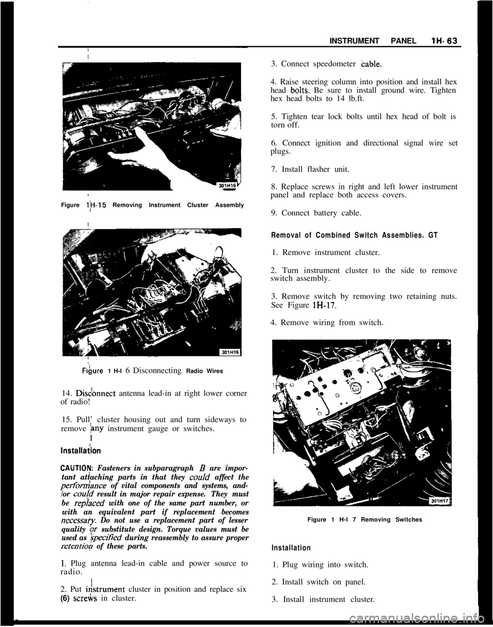
,INSTRUMENT PANELlH-63Figure l;H-15 Removing Instrument Cluster AssemblyFibure1 H-l 6 Disconnecting Radio Wires
14. Disdonnect antenna lead-in at right lower corner
of radio!
15. Pull’ cluster housing out and turn sideways to
remove
&~y instrument gauge or switches.
I
lnstallaiion
CAUTlOI$ Fasteners in subparagraph B are impor-
tant attaching parts in that they coo/d
affect the
perform>nce of vital components and systems, and-
/or
cou!d result in major repair expense.They must
be
repraced with one of the same part number, or
with an equivalent part if replacement becomes
necessa?y. Do not use a replacement part of lesser
quality
br substitute design. Torque values must be
used as
&ified during reassembly to assure proper
retention of these parts.
1. Plug antenna lead-in cable and power source to
radio. I
2. Put i&trument cluster in position and replace six
(6) screbs in cluster.3. Connect speedometer cable.
4. Raise steering column into position and install hex
head
bolt% Be sure to install ground wire. Tighten
hex head bolts to 14 lb.ft.
5. Tighten tear lock bolts until hex head of bolt is
torn off.
6. Connect ignition and directional signal wire set
plugs.
7. Install flasher unit.
8. Replace screws in right and left lower instrument
panel and replace both access covers.
9. Connect battery cable.
Removal of Combined Switch Assemblies. GT1. Remove instrument cluster.
2. Turn instrument cluster to the side to remove
switch assembly.
3. Remove switch by removing two retaining nuts.
See Figure lH-17.
4. Remove wiring from switch.
Figure 1 H-l 7 Removing Switches
Installation1. Plug wiring into switch.
2. Install switch on panel.
3. Install instrument cluster.
Page 93 of 625

1 J- 72 1973 OPEL SERVICE MANUAL
I
WIRING IDIAGRAMS
CONTENTS
Subject
1973 WIRING DIAGRAMS: Windshield Wiper and
Horn:- Opel 1900 -
Manta....................................I.............. ..............................
Windshield Wiper and Horn’- Rallye ..........................
Windshield Wiper
andHorn!-GT
..................................
Turn Signal and Hazard Flasher
-
Opel 1900 - Manta !
........................................................
Turn Signal and Hazard Flasher
- GT ..........................
Oil, Fuel,
Temp.: Tach, Stop and Brake
Warning Light
.GT........................................................
Blower Motor, Lighter and
Rackup Lights -
Qpel 1900.Manta ........................................................
Blower Motor and Lighter
.,GT....................................
Indicator Lights and Gauges
- Opel 1900 -
Manta ........................................................................\
........
Indicator Lights
andGauges.Rallye ..........................
Dome Light and Buzzer
- Opel 1900 - Manta..........
Dome Light, Buzzer and Clock - GT ............................
Headlamps
- Opel 1900 ’
....................................................
Headlamps
.Mantaj............................................................
Headlamps and Fog Lights
.Rallye ..............................
Headlamps, Parking, Tail and Instrument
PanelLighting.GT ........................................................
Left Parking and Tail Lights
- Opel 1900 -
Manta ..................................i.............................................
Right Parking and Tail Lights
- Opel 1900 -
Manta................. ..*............................................................
Starting, Ignition and Charging
-
Opel 1900.Manta..........i.............................................
Starting, Ignition and Charging
- GT ..........................
Instrument
Panel.GT ......................................................
A/C Generatorand Regulator
- All Models..............
Seat Belt Warning System (Manual Transmission)
-Opel1909-Manta ..........................
Seat Belt Warning System (Automatic Transmission)
.Opel 1900 - Manta..........................
Seat Belt Warning System (Manual Transmission)
- GT........................................................ Page No.
1 J-74
1 J-75
1 J-76
1 J-77
1 J-78
1 J-79
1 J-80
lJ-81
1 J-82
1 J-83
1 J-84
1 J-85
1 J-86
1 J-87
1 J-88
1 J-89
1 J-90
1 J-91
1 J-92
1 J-93
1 J-94
1 J-95
1 J-96
1 J-97
1 J-98
Page 105 of 625

r
2UREDp
IM
BRNIWHI
BUZZER
3 CLOSED POSlTlONl
/-
14 RED - TO STEERING
COLUMN CONN.
20 RED
12 RED FROM BATTERY--18 GRAY--12 RED
-I
J
DOME LIGHT
&SWITCH1
1
.,_ &,,,.~~
STEER I NG
COLUMN
CONNECTORTRUNK LIGHT?&SWITCH
IGNITION
SWITCH‘\BUZZER SWITCH(HELD CLOSED WITH
KEY IN “OFF” & “LOCK”POSITION1
3OlJll
Page 114 of 625

I
I
WIRING DIAGRAMSlJ- 93
I
Figure
lJ-20 Starting, Ignition and Charging GT