jump start OPEL GT-R 1973 Service Manual
[x] Cancel search | Manufacturer: OPEL, Model Year: 1973, Model line: GT-R, Model: OPEL GT-R 1973Pages: 625, PDF Size: 17.22 MB
Page 51 of 625

i
1 D- 301973 OPEL SERVICE MANUAL
6. Make sure all electrical accessories are turned (lff.
Start engine with battery post adapter switch closed;
open switch as soon as engine
iS: started.
7. Adjust engine speed to 2500 RPM.
8. Turn tester control knob to “LOAD” position
aid
adjust knob to obtain highest possible ammeter r&d-
ing. Output must be 30 amperes minimum. If
outcut
is okay, proceed to voltage regulator test below. j
/.9. If output is low, defect may be in alternator or m
regulator. To eliminate regulator, supply field &-
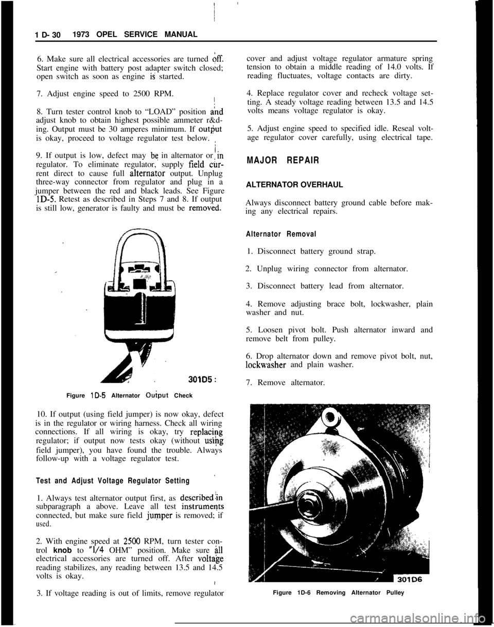
rent direct to cause full alternat,or output. Unplug
three-way connector from regulator and plug in a
jumper between the red and black leads. See Figure
lD-5. Retest as described in Steps 7 and 8. If output
is still low, generator is faulty and must be
remov&d.
301D5 :
Figure lD-5 Alternator Ouiput Check I
10. If output (using field jumper) is now okay, defect
is in the regulator or wiring harness. Check all wiring
connections. If all wiring is okay, try
replac/~g
regulator; if output now tests okay (without
uslpg
field jumper), you have found the trouble. Always
follow-up with a voltage regulator test.
Test and Adjust Voltage Regulator Setting
1. Always test alternator output first, as describedlin
subparagraph a above. Leave all test
instrumeqts
connected, but make sure field
jumper is removed; if
used.
2. With engine speed at 2500 RPM, turn tester con-
trol
knob to “l/4 OHM” position. Make sure ill
electrical accessories are turned off. After volt&e
reading stabilizes, any reading between 13.5 and 14.5
volts is okay.
3. If voltage reading is out of limits, remove regulator cover and adjust voltage regulator armature spring
tension to obtain a middle reading of 14.0 volts. If
reading fluctuates, voltage contacts are dirty.
4. Replace regulator cover and recheck voltage set- ting. A steady voltage reading between 13.5 and 14.5
volts means voltage regulator is okay.
5. Adjust engine speed to specified idle. Reseal volt-
age regulator cover carefully, using electrical tape.
MAJOR REPAIR
ALTERNATOR OVERHAUL
Always disconnect battery ground cable before mak-
ing any electrical repairs.
Alternator Removal
1. Disconnect battery ground strap.
2. Unplug wiring connector from alternator. 3. Disconnect battery lead from alternator.
4. Remove adjusting brace bolt, lockwasher, plain
washer and nut.
5. Loosen pivot bolt. Push alternator inward and
remove belt from pulley.
6. Drop alternator down and remove pivot bolt, nut,
lockwasher and plain washer.
7. Remove alternator.
Figure 1D-6 Removing Alternator Pulley
Page 356 of 625

TUNE-UP
ALL MODELS
CONTENTS
Subject
DESCRIPTION AND OPERATION:
Purpose of a Tune-Up. . . . . . . . . . . . . . . . . . . . . . . . . . . . . . . . . . . . . . . . . . . . . . . . . , . . . .DIAGNOSIS: (Not Applicable)
MAINTENANCE AND ADJUSTMENTS:
EngineTune-UpMechanicalOperations. . . . . . . . . . . . . . . . . . . .
EngineTune-UpInstrumentChecks. . . . . . . . . . . . . . . . . . . . . . . . . . . .MAJOR REPAIR: (Not Applicable)
SPECIFICATIONS:
Tune-Uo Soecifications and Adjustments
. . . . . . . . . . . . . . . .Page No.6G-65
6G-6566-6766-68
DESCRIPTION AND OPERATION
PURPOSE OF TUNE-UP
The purpose of an engine tune-up is to restore powerand performance that may have been lost through,
loss of adjustment, wear, corrosion, or deterioration
of one or more parts or units. In the normal operat-
ion of an engine, these changes take place gradually
at quite a number of points so that it is seldom advis-able to attempt an improvement in performance by
correcting one or two items only. Time will be savedand more lasting results will be assured by following
a definite and thorough procedure of analysis and
correction of all items affecting power and perform-
ance. Because of Federal laws, limiting exhaust emis-sions, it is even more important that the engines
tune-up is done accurately, using the specifications
listed and the tune-up sticker found in each engine
compartment.
Economical, trouble free operation can better be as-sured if a complete tune-up is performed at first 4
months or
6,ooO miles of operation - then at 12
month or 12,000 mile intervals.
The parts or units which affect power and perform-
ance may be divided, into three groups (1) compres-sion, (2) ignition and (3) carburetion. The tune-up
procedure should cover these groups in the order
given. While the items affecting compression and
ignition may be handled according to individual
preference, correction of items in the carburetiongroup should not be attemplcu
ulllll all items in
compression and ignition have been satisfactorily
corrected.
MAINTENANCE AND ADJUSTMENTS
ENGINE TUNE-UP OPERATIONS
CompressionTo make sure hydrocarbon and carbon monoxide
emissions will be within limits, it is very important
that the adjustments be followed exactly.
The suggested procedure for engine tune-up is as
follows:1. Remove all spark plugs.
2. Position throttle and choke valve in full open posi-tion.
3. Connect jumper wire between distributor terminalof coil and ground on engine to avoid high tension
sparking while cranking engine.
4. Hook up starter remote control cable and turn
ignition switch to “on” position.
5. Firmly insert compression gage in spark plug port.Crank engine to obtain highest possible reading.