lock OPEL GT-R 1973 Owner's Guide
[x] Cancel search | Manufacturer: OPEL, Model Year: 1973, Model line: GT-R, Model: OPEL GT-R 1973Pages: 625, PDF Size: 17.22 MB
Page 80 of 625

/
I
IINSTRUMENT PANELlH- 59
Figure 1 H-2
- GT Instrument and Switch Arrangement
The Wihdshield Wipers have two-speed operation.
By pushing the lower half of the switch inward to the
first stop, the wipers will operate at half speed and
by deprbssing to the second stop will provide full
speed oieration. When the switch is returned to the
off posit/on, the wiper blades automatically return to
their park position.
I
The El
this optlpn. The engine must be running before
suffi-cient current can be generated to energize this circuit
even th6ugh the switch is depressed to the “ON”
position! When the window is being heated, a warm-
ing light’on the instrument panel will glow. This light
is locate? below the left ventilation inlet.
The
Heiter Blower Switch is a three position switch.
By depressing the lower half of the switch to the first
stop,
th& blower will operate at low speed. Whendepressdd to the second stop, the blower will operate
at high ipeed.
Four Way Hezrerd Warning Flasher SwitchThe
hazard warning flasher switch is located below
the heater controls in the center console. By
depress-ing the lower half of the switch, all four turn- signal
lamps flash at the same time. Although this system
makes use of the regulat turn signal system, it has a
separate feed wire to the switch which allows for its
operation even with the ignition switch and doors
locked. No vehicle should be driven with this system
in operation because of its universal meaning “This
Vehicle Is Not Moving”. To turn the system off,
simply depress the upper half of the switch.
MAJOR REPAIR
Removal of Instrument Cluster Housing Assembly.Opel 1900 Manta
Before starting any instrument panel repair, always
disconnect battery ground cable first.
I
Page 81 of 625

/
I1 H- 601973 OPEL SEW& MANUAL
1. Remove headlight switch button by depressing
retaining clip on shaft and pulling back on switch
knob. See Figure lH-3.
Figure 1 H-5
- Removing Cluster Screws
Figure lH-3
- Removing Headlight Switch Knob,
2. Remove two (2) plugs on cluster panel. See FigurelH-4.301H6
-Figure 1 H-4 Removing Plugs
3. Remove two (2) sheet metal screws behind plugs
on cluster. See Figure lH-5.
4. Pull off heater control knobs toward front.
j5. On top, carefully pull instrument ‘trim plate
:to-wards steering wheel and remove plate.
6. Remove two screws for lower housing
attach&t.See Figure lH-6.Figure 1 H-6 Lower Housing Attaching Screws
7. Disconnect speed0 cable at cluster by turning cou-
pling counterclockwise.
8. If equipped, pull heated rear window or fog lamp
switch out of instrument housing and disconnect
wires from switches.
9. Pull cluster right and left sides partially out and
disconnect wires on back of cluster. See Figure lH-7.
Installation
1.
P&e instrument cluster in position and connect
wires on back of cluster.
2. Pull fog light or heated back glass switch wires
into opening, if equipped, and connect wires and
replace switch.
3. Connect two screws on lower housing attachment.
Page 82 of 625

I
I
IINSTRUMENT PANELlH- 61Figwe 1 H-7
- Disconnecting Cluster Wires
4. Install instrument cluster trim plate and replace
two screw and plugs.
5. Con&t speed0 cable by turning coupling clock-
wise. 1
6. Install light
.switch button and heater control
knobs. I
I
7. Con+ct battery cable.
Removidg Windshield Wiper Switch - Opel 1900Manta I
1.
Rem* instrument cluster trim plate.
2. Corndress retaining clips and remove switch. See
Figure iH-8.
I
Figure lH-8 . Removing Windshield Wiper Switch3. Disconnect wiring connector.
Installation1. Connect wiring to switch.
2. Snap switch back into panel.
3. Replace instrument cluster trim plate.
Removing Instrument Cluster Bulbs - Opel 1900.
Manta1. Remove instrument cluster assembly.
2. Replace bulbs from back ofcluster. See Figure
lH-
9.Figure lH-9 Removing Instrument
Clu’ster Bulbs
Installation1. Replace bulbs in cluster.
2. Replace instrument cluster assembly.
Removing and Installing Ignition SwitchRefer to Group 3, Section F.
Removal of Instrument Cluster Housing Assembly.
GTDisconnect battery before making any electrical re-
pairs.
1. Disconnect battery cable.
2. Remove right access cover and remove screw. See
Figure lH-10.
Page 84 of 625

I
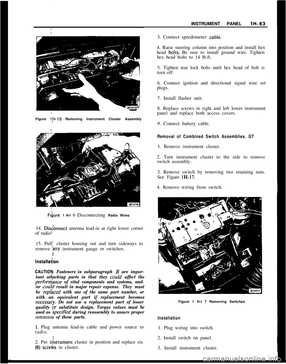
,INSTRUMENT PANELlH-63Figure l;H-15 Removing Instrument Cluster AssemblyFibure1 H-l 6 Disconnecting Radio Wires
14. Disdonnect antenna lead-in at right lower corner
of radio!
15. Pull’ cluster housing out and turn sideways to
remove
&~y instrument gauge or switches.
I
lnstallaiion
CAUTlOI$ Fasteners in subparagraph B are impor-
tant attaching parts in that they coo/d
affect the
perform>nce of vital components and systems, and-
/or
cou!d result in major repair expense.They must
be
repraced with one of the same part number, or
with an equivalent part if replacement becomes
necessa?y. Do not use a replacement part of lesser
quality
br substitute design. Torque values must be
used as
&ified during reassembly to assure proper
retention of these parts.
1. Plug antenna lead-in cable and power source to
radio. I
2. Put i&trument cluster in position and replace six
(6) screbs in cluster.3. Connect speedometer cable.
4. Raise steering column into position and install hex
head
bolt% Be sure to install ground wire. Tighten
hex head bolts to 14 lb.ft.
5. Tighten tear lock bolts until hex head of bolt is
torn off.
6. Connect ignition and directional signal wire set
plugs.
7. Install flasher unit.
8. Replace screws in right and left lower instrument
panel and replace both access covers.
9. Connect battery cable.
Removal of Combined Switch Assemblies. GT1. Remove instrument cluster.
2. Turn instrument cluster to the side to remove
switch assembly.
3. Remove switch by removing two retaining nuts.
See Figure lH-17.
4. Remove wiring from switch.
Figure 1 H-l 7 Removing Switches
Installation1. Plug wiring into switch.
2. Install switch on panel.
3. Install instrument cluster.
Page 86 of 625

GAUGES
CONTENTS
Subject
DESCRIPTION AND OPERATION:
DIAGNOSIS:
Temperature and Fuel Gauge
System-Opel1900-Manta. . . . . . . . . . . . . . . . . . . . . . . . . . . . . . . . . . . . . . . . . .
FuelGauge-GT. . . . . . . . . . . . . . . . . . . . . . . . . . . . . . . . . . . . . . . . . . . . . . . . . . . . . . . . . . . . . . . . . .MAINTENANCE AND ADJUSTMENTS:
MAJOR REPAIR:
Opel 1900
- Manta
Voltage Stabilizer
. . . . . . . . . . . . . . . . . . . . . . . . . . . . . . . . . . . . . . . . . . . . . . . . . . . . . . . .Speedometer
. . . . . . . . . . . . . . . . . . . . . . . . . . . . . . . . . . . . . . . . . . . . . . . . . . . . . . . . . . . . . . . . . . . .Electric
ClockorTachometer. . . . . . . . . . . . . . . . . . . . . . . . . . . . . . . . . . . .Temperature Indicator or Fuel Gauge
. . . . . . . . . . . . . . . . . . . .Rallye
Gauges. . . . . . . . . . . . . . . . . . . . . . . . . . . . . . . . . . . . . . . . . . . . . . . . . . . . . . . . . . . . . . . . . .Temperature
SendingUnit. . . . . . . . . . . . . . . . . . . . . . . . . . . . . . . . . . . . . . . . . .Oil Pressure Sending Unit
. . . . . . . . . . . . . . . . . . . . . . . . . . . . . . . . . . . . . . . . . .GT
Speedometer
. . . . . . . . . . . . . . . . . . . . . . . . . . . . . . . . . . . . . . . . . . . . . . . . . . . . . . . . . . . . . . . . . . . .Tachometer
. . . . . . . . . . . . . . . . . . . . . . . . . . . . . . . . . . . . . . . . . . . . . . . . . . . . . . . . . . . . . . . . . . . . . .Temperature Indicator and Fuel Gauge Dash, Unit
Electric
Clock. . . . . . . . . . . . . . . . . . . . . . . . . . . . . . . . . . . . . . . . . . . . . . . . . . . . . . . . . . . . . . . . . .Ammeter
andOilPressureGauge. . . . . . . . . . . . . . . . . . . . . . . . . . . .SPECIFICATIONS:
DIAGNOSISITEM(ERATURE
& FUEL GAUGE - SYSTEM
DIAGNOSIS (OPEL 1900, MANTA)
/
ConditionPossible Cause
I
Page No.
1l-65
1l-67
1l-67
1l-68
1l-68
1l-69
1l-69
1l-69
1l-70
1l-70
1l-70
1l-70
1l-71
1l-71
Correction
Temperature and gas gaugeinopetative1. Blown fuse1. Replace fuse. If new fuse
blows, repair short.
2. Defective voltage
stabilizer1. Install 40 ohm resistors
between ground
& connectors
(disconnect from units)
of temperature sending imit
and gas gauge tank unit. If
both dash units do not move
to full scale (tolerance
-one pointer width of either
side of full scale reading)
and the distance of movement
on the scale is the same,,
replace the voltage stabdner.
Page 89 of 625

1 I- 68 1973 OPEL SERVICE MANUAL
2. Pull voltage stabilizer of back of printed circhit.
See Figure
11-l.
!
L-_ -~~---,~. _^__, _-_~
Figure 1 l-3 - Speedometer Attaching Screws
Figure
11-l -Voltage Stabilizer
installation
2. Install six (6) screws holding instrument cluster
lens in housing.
3. Replace cluster housing.
1. Install voltage stabilizer on
back of printed circuit.
2. Install instrument cluster
ho*sing assembly. j
I
Removing Speedometer I
1. Remove instrument cluster housing.:
2. Remove six screws shown in Figure
11-2 and
remove both instrument
cluster’lens.
Figure 1 l-2 - Removing Instrument Cluster Lens
3. Remove three speedometer attaching screws. L&X
Figure 11-3.
/
Installation
1. Replace speedometer in cluster with three (3) at-
taching screws.
Removing Electric Clock or Tachometer
1. Remove instrument housing.
2. Remove six screws and remove both instrument
cluster lens, as shown in Figure
11-2.
3. Remove three screws, as shown in Figure 11-4, and
remove clock or tachometer.
L-u-.------ _._- -----G1.-A-... -.
Figure 1 l-4 - Removing Electric Clock or Tachometer
1. Install clock or tachometer in instrument cluster
with three (3) attaching screws.
2. Install six (6) screws holding instrument cluster
lens.
Page 91 of 625

lb 70 1973 OPEL SERVlCE!MANUAL
Removing Oil Pressure Sending Upit1. Disconnect wire from sending
Fit.2. Unscrew oil pressure sending
u?it from block. St&Figure
11-7./
Figure
11.7 - Oil Pressure Sending Unit
Installation1. Replace oil pressure sending unit into block.
2. Connect wire to unit.
Figure 1 l-8 Rear View of SpeedometerI
Removal of Speedometer1. Remove instrument housing.
2.Remove speedometer. See Figure 11-9 1.
Installation
1.Install speedometer.
2.Install instrument housing, paragraph 11-71.per
Removal of Tachometer1. Remove instrument housing.
2.Remove tachometer.
3.Disconnect electrical wires. See Figure 11-9.
Figure
11-9 Rear View of Tachometer
Installation1. Connect wires.
2. Install tachometer.
3. Install instrument cluster.
Removal of Temperature Indicator and Fuel GaugeDash Unit
1. Remove instrument housing.
2. Remove temperature indicator and fuel gauge
dash unit.
3. Disconnect electrical wires. See figure
11-10.
Page 92 of 625

I
IGAUGESll- 71
Figure 1
IL10 Rear View of Temperature Indicator and
I
IFuel Gauge Dash Unit
I
Install&m1. Connekt wires and install unit.
2. Install! instrument cluster housing.
I
Removal
\of Electric Clock
1.
Remoie instrument housing.
Figuy 1 I-1 1 Rear View of Electrical Clock
I2. Remove electrical clock.
3. Disconnect electrical wires. See Figure
11-I I.
Installation
1. Install clock and connect wires.
2. Install instrument cluster housing.
Removal of Ammeter and Oil Pressure Gauge
1. Remove instrument housing.
2. Remove ammeter and oil pressure gauge.
3. Disconnect electrical wires. See Figure
11-12.Figure 1 I-1 2 Rear View of Ammeter and Oil Pressure
GaugeInstallation
1. Connect wires to ammeter and oil pressure gauge
and install.
2. Install instrument cluster housing.
Page 93 of 625

1 J- 72 1973 OPEL SERVICE MANUAL
I
WIRING IDIAGRAMS
CONTENTS
Subject
1973 WIRING DIAGRAMS: Windshield Wiper and
Horn:- Opel 1900 -
Manta....................................I.............. ..............................
Windshield Wiper and Horn’- Rallye ..........................
Windshield Wiper
andHorn!-GT
..................................
Turn Signal and Hazard Flasher
-
Opel 1900 - Manta !
........................................................
Turn Signal and Hazard Flasher
- GT ..........................
Oil, Fuel,
Temp.: Tach, Stop and Brake
Warning Light
.GT........................................................
Blower Motor, Lighter and
Rackup Lights -
Qpel 1900.Manta ........................................................
Blower Motor and Lighter
.,GT....................................
Indicator Lights and Gauges
- Opel 1900 -
Manta ........................................................................\
........
Indicator Lights
andGauges.Rallye ..........................
Dome Light and Buzzer
- Opel 1900 - Manta..........
Dome Light, Buzzer and Clock - GT ............................
Headlamps
- Opel 1900 ’
....................................................
Headlamps
.Mantaj............................................................
Headlamps and Fog Lights
.Rallye ..............................
Headlamps, Parking, Tail and Instrument
PanelLighting.GT ........................................................
Left Parking and Tail Lights
- Opel 1900 -
Manta ..................................i.............................................
Right Parking and Tail Lights
- Opel 1900 -
Manta................. ..*............................................................
Starting, Ignition and Charging
-
Opel 1900.Manta..........i.............................................
Starting, Ignition and Charging
- GT ..........................
Instrument
Panel.GT ......................................................
A/C Generatorand Regulator
- All Models..............
Seat Belt Warning System (Manual Transmission)
-Opel1909-Manta ..........................
Seat Belt Warning System (Automatic Transmission)
.Opel 1900 - Manta..........................
Seat Belt Warning System (Manual Transmission)
- GT........................................................ Page No.
1 J-74
1 J-75
1 J-76
1 J-77
1 J-78
1 J-79
1 J-80
lJ-81
1 J-82
1 J-83
1 J-84
1 J-85
1 J-86
1 J-87
1 J-88
1 J-89
1 J-90
1 J-91
1 J-92
1 J-93
1 J-94
1 J-95
1 J-96
1 J-97
1 J-98
Page 105 of 625

r
2UREDp
IM
BRNIWHI
BUZZER
3 CLOSED POSlTlONl
/-
14 RED - TO STEERING
COLUMN CONN.
20 RED
12 RED FROM BATTERY--18 GRAY--12 RED
-I
J
DOME LIGHT
&SWITCH1
1
.,_ &,,,.~~
STEER I NG
COLUMN
CONNECTORTRUNK LIGHT?&SWITCH
IGNITION
SWITCH‘\BUZZER SWITCH(HELD CLOSED WITH
KEY IN “OFF” & “LOCK”POSITION1
3OlJll