lock OPEL GT-R 1973 User Guide
[x] Cancel search | Manufacturer: OPEL, Model Year: 1973, Model line: GT-R, Model: OPEL GT-R 1973Pages: 625, PDF Size: 17.22 MB
Page 39 of 625
1 C- 18 1973 OPEL SERVICE MANUAL
IGNITIPN SYSTEM
CbNTENTS
Subject
DESCRIPTION AND OPERATION: Ignition System ..................................................................
Ignition
Switc,h....................................................................
Ignition Coil
..........................................................................\
Distributor
............................I...............................................
DIAGNOSIS: (Not Available)
MAINTENANCE AND ADJUSTMENTS: Contact PointReplacement ............................................
Dwell Angle Adjustment :
................................................
Ignition Timing Adjustment ..........................................
Ignition Wire Inspection :
..................................................
Check Ignition Output ......................................................
Check Distributor
..............................................................
Check Spark Plugs
............................................................
MAJOR REPAIR: Distributor Removal ..........................................................
Disassembly ........................
I...............................................
Reassembly
..........................I...............................................
Distributor Installation
....................................................
SPECIFICATIONS: /
Ignition
Coil ..........................................................................
Distributor
....‘........................i...............................................
Spark Plugs ........................................................................\
..
DESCRIPTION AND OPERATION
INGITION SYSTEM
The ignition system basically consists of an ignitipn
switch, ignition coil, distributor, battery and related
wiring. The ignition switch is located in the steering
column, the ignition coil is located left front inner fender
skirt and the distributor is located at the left
front of the engine.
IGNITION SWITCH
The combined ignition switch and steering lock ian
be switched to any one of the below listed positions.
Insert key with notch pointing upward.
Page No.
lC-18
lC-18
lC-19
lC-19
1 c-20
1 c-20
1 c-20
lC-21 r
lC-21
1 c-22
1 c-22
1 r-23
1 C-23
1 c-24
1 C-25
1 C-26
1 C-26
1 C-26
(Fully counterclockwise) Lock position. Ignition
locked, steering locked, only with key removed.
Electrical circuits disconnected except to main light-
ing switch and dome lamp. The
key can be removed.
0- (First position clockwise from lock) Garage posi-
tion. ‘The key and lock assembly must be pushed “in”
to reach this position from lock. The steering is un-
locked and the ignition is off. The electrical circuits
are the same as in lock position. The key cannot be withdrawn.
l- [Chposition.) All electrical circuits controlled by
ignition switch are completed through the switch.
The key cannot
be removed while switch is in drive
position.
Page 41 of 625
I
ilC- 201973 OPEL SERVICE MANUAL
There is also a plastic hood slipped over the distrivu-tar cap with an outlet for the ignition cables as an
added protection against moisture from the outside.
See Figure lC-2.
Figure lC-2 Ignition Distributor With Hood Installed
MAINTENANCE AND ADJUSTMENTS
CONTACT POINT REPLACEMENT
Removing Contact Points1. Remove contact support lock
,screw and remqve
contact point support. If condenser is to be replaced,
it will be necessary to replace condenser and
1eads;asan assembly.
Installing Contact Points1. Lightly lubricate distributor cam with high tein-perature cam and ball bearing lubricant. Excessive
lubricant will throw off into contact points.
:
,
2. Position support on breaker plate and install lock
screw leaving slightly loose for later adjustment..
3. Plug breaker arm wire in.
4. Adjust breaker point gap to ,016”.
/
DWELL ANGLE ADJUSTMENT
1. Connect dwell meter.
2. Remove distributor cap. Remove rotor. Loosen
breaker point set screw approximately
l/8 turn.
3. Insert screwdriver in notch of stationary breaker
point. Observe dwell meter while cranking engine.
Twist screwdriver as required to obtain a reading of
50 degrees plus or minus 3 degrees.4. Tighten breaker point set screw, then recheck
dwell.
5. Install rotor and cap.~Start engine and recheck
dwell. It is important that dwell be rechecked, as
instal~lation of rotor and cap will sometimes change
the dwell angle.
IGNITION TIMING ADJUSTMENT
Preliminary Timing (Engine Won’t Run)To time the ignition on any engine which will run,
use subparagraph b only. However, if the timing of
an engine is completely off, the following procedure
must first be used to get the engine to run.
1. With rocker arm cover removed, rotate crankshaft
in a clockwise direction until both valves for No. 1
cylinder are closed and the timing marks line-up.
(Valves are completely closed if rocker arms can be
“rocked” slightly.)
2. Install distributor in engine so that vacuum ad-
vance unit is in original position and notch in dis-
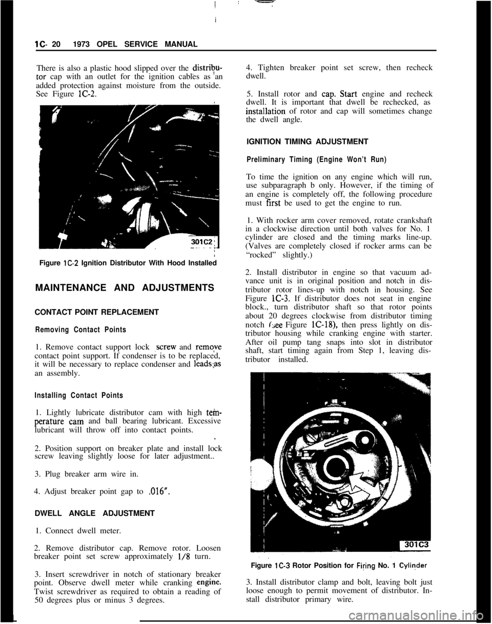
tributor rotor lines-up with notch in housing. See
Figure lC-3. If distributor does not seat in engine
block., turn distributor shaft so that rotor points
about 20 degrees clockwise from distributor timing
notch
(see Figure lC-18), then press lightly on dis-
tributor housing while cranking engine with starter.
After oil pump tang snaps into slot in distributor
shaft, start timing again from Step 1, leaving dis-
tributor installed.
Figure lC-3 Rotor Position for Filing No. 1 Cyliqder
3. Install distributor clamp and bolt, leaving bolt just
loose enough to permit movement of distributor. In-
stall distributor primary wire.L
Page 42 of 625
IGNITION SYSTEMlC-214. Rota&distributor counterclockwise slightly until
contact pbints just start to open. This must be done
very carefully or engine will not start.
5. Install distributor cap. Make sure spark plug wires
are correctly installed in distributor cap, through clip
and on spark plugs.
Finish TimingIContact boint gap
(.016” at widest gap) or dwell 50
degrees plus or minus 3 degrees should always be
checked before adjusting ignition timing.
1. Connekt timing light to No. 1 spark plug.
2. Disconnect and plug vacuum advance unit and
retard u$it hoses.
3. Connect a tachometer from distributor side of coil
to
groun$l.4. Start dngine. Set idle speed to 900 RPM.
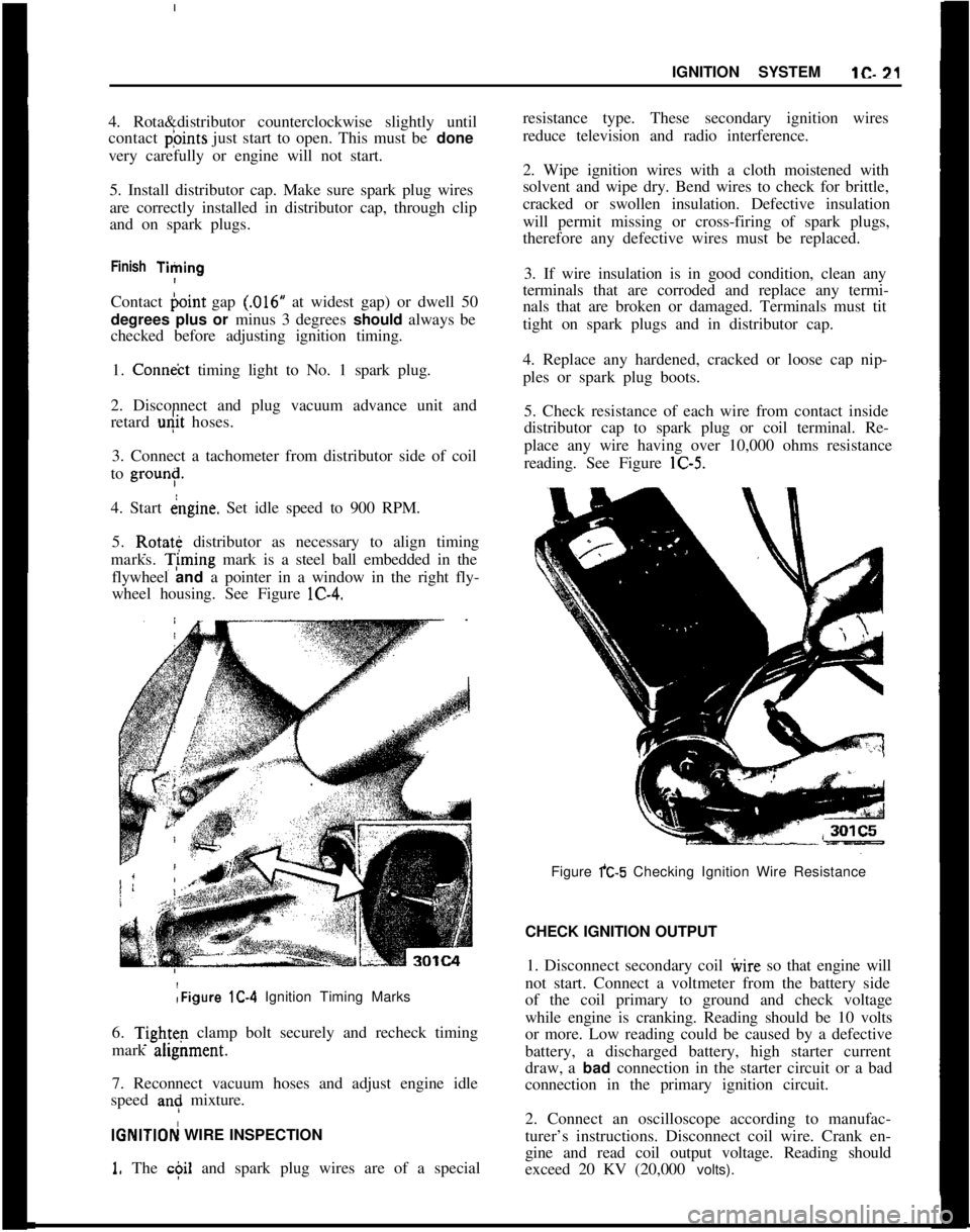
5. Rotate distributor as necessary to align timing
marks. T;ming mark is a steel ball embedded in the
flywheel and a pointer in a window in the right fly-
wheel housing. See Figure lC-4.:Figure lC-4 Ignition Timing Marks
6.
Tightq clamp bolt securely and recheck timing
mark ahgnment.
7. Reconnect vacuum hoses and adjust engine idle
speed
an: mixture.
IGNlTlOFj WIRE INSPECTION
1. The c$il and spark plug wires are of a specialresistance type. These secondary ignition wires
reduce television and radio interference.
2. Wipe ignition wires with a cloth moistened with
solvent and wipe dry. Bend wires to check for brittle,
cracked or swollen insulation. Defective insulation
will permit missing or cross-firing of spark plugs,
therefore any defective wires must be replaced.
3. If wire insulation is in good condition, clean any
terminals that are corroded and replace any termi-
nals that are broken or damaged. Terminals must tit
tight on spark plugs and in distributor cap.
4. Replace any hardened, cracked or loose cap nip-
ples or spark plug boots.
5. Check resistance of each wire from contact inside
distributor cap to spark plug or coil terminal. Re-
place any wire having over 10,000 ohms resistance
reading. See Figure lC-5.
Figure fC-5 Checking Ignition Wire Resistance
CHECK IGNITION OUTPUT
1. Disconnect secondary coil ivire so that engine will
not start. Connect a voltmeter from the battery side
of the coil primary to ground and check voltage
while engine is cranking. Reading should be 10 volts
or more. Low reading could be caused by a defective
battery, a discharged battery, high starter current
draw, a bad connection in the starter circuit or a bad
connection in the primary ignition circuit.
2. Connect an oscilloscope according to manufac-
turer’s instructions. Disconnect coil wire. Crank en-
gine and read coil output voltage. Reading should
exceed 20 KV (20,000 volts).
Page 43 of 625
lC- 22 1973 OPEL SERVICE MANUAL j
3. Start engine and disconnect a wire from a spark
plug. Read output voltage of disconnected spark
plug circuit. Reading should exceed 20 KV
(20,poO
volts).I
CHECK DISTRIBUTOR
!1. Clean distributor cap and inspect it for cracks or
tracking. Inspect inner segments for erosion and
outer sockets for corrosion.
2. Clean and inspect ignition wires. Make sure resist-
ance of each wire is less than 10,000 ohms. Replace
any defective spark plug boots or distributor
capnipples. See paragraph lC-12.
3. Inspect breaker points and replace if necessary.
Adjust breaker point gap to
,016 inch with rubbing
block on peak of cam lobe or check dwell and adjust
if not 50 degrees plus or minus 3 degrees. 4. Check
dwell variation by reading dwell at idle and at 3000
RPM. Dwell must not vary more than 3 degrees.
Excessive variation means distributor shaft, cam or
breaker plate are worn or damaged--overhaul dis-
tributor and replace defective parts.
5. Check distributor condenser for a minimum series
resistance and insulation leakage. Check for a
capacity between
.15 and .20 microfarads.
6. Check total advance (centrifugal and vacuum) at
2500 engine RPM using a timing light having a dial
for reading advance.
(a) The timing marks are aligned with both the
vacuum advance and the vacuum retard hoses dis-
connected and plugged.
Engine idle should be 900 RPM.
(b) Reconnect vacuum hoses. Run engine at
3600RPM and adjust knob until timing marks are
aligned. Read advance on dial. Maximum centrifugal
advance should be between 28-32 degrees.
7. If total advance is out of specifications, check
centrifugal advance only, at
2500 RPM. Discon+ectand plug all vacuum hoses. Maximum vacuum ad-
vance should be l-5 degrees at 4.5-5.0 in. hg.
8. Replace centrifugal or vacuum advance parts as
required to bring distributor total advance within
specifications.
9. Check operation of vacuum retard unit (rear unit)
by first making sure timing marks are aligned with
vacuum hoses disconnected and at slow idle (700
RPM). Then connect vacuum hose to vacuum retard
unit (rear unit). Timing ball should move in a retard
direction (upward).
CHEICK SPARK PLUGS1. Remove spark plugs. If electrodes are badly worn,
discard plugs. If inner or outer porcelain is cracked
or broken, discard plugs.
2. Note color and general appearance of inner end of
spark plug. Brown to grayish
- tan deposits and slight
electrode wear indicate correct spark plug heat
range. Plugs having this appearance may be cleaned,
regapped, tested and reinstalled.
3. Clean spark plugs in a sand blast type cleaner.
Clean only enough to remove deposits, not enough to
wear away porcelain. If deposits are too hard to
remove or if porcelain is glazed, discard plugs.
4. After cleaning spark plugs, clean tiring surfaces of
electrodes with a line file.
5. Test cleaned spark plugs on a pressure tester by
comparing spark of the used plugs with that of a new
plug. Install tested plugs, using new gaskets.
6. If removed spark plugs have excessive carbon foul-
ing and if the car will be driven mostly at low speeds
in city driving, it is advisable to replace plugs with
a hotter plug, AC43FS.
7. If removed plugs show rapid electrode wear or
inner porcelain breakage at low mileage. Check for
a vacuum leak such as a poor manifold to head fit.
8.
Clap spark plugs carefully (new or cleaned) using
a
,030 round wire feeler gage.IC6
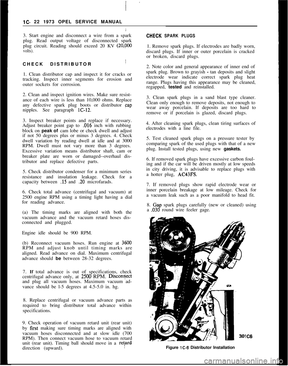
Figure lC-6 Distributor Installation
Page 44 of 625
IGNITION SYSTEMlC- 23
9. Install:spark plugs using a 13/16 deep socket, an
extension and a torque wrench. Tighten to 22-29Ib.ft. 1
MAJOR REPAIRDlSTRlBtiTOR OVERHAULDistributbr Removal
1. Remove fuel pump. This is necessary because the
fuel
punp will block the distributor drive gear,
thereby preventing removal of the distributor. See
Figure lC-6.
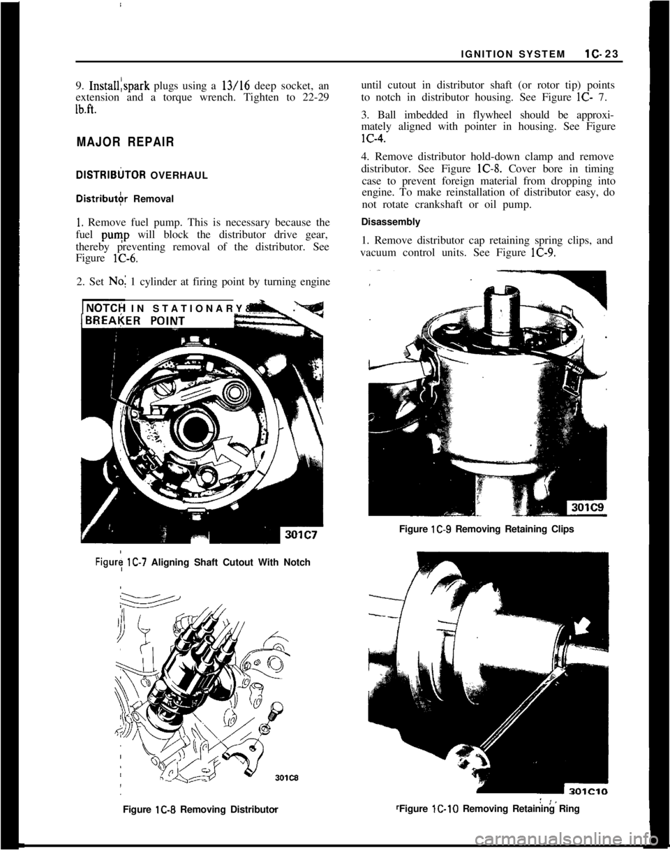
2. Set No; 1 cylinder at firing point by turning engine
INOTCH IN STATIONARY& -.until cutout in distributor shaft (or rotor tip) points
to notch in distributor housing. See Figure
lC- 7.
3. Ball imbedded in flywheel should be approxi-
mately aligned with pointer in housing. See FigurelC-4.
4. Remove distributor hold-down clamp and remove
distributor. See Figure lC-8. Cover bore in timing
case to prevent foreign material from dropping into
engine. To make reinstallation of distributor easy, do
not rotate crankshaft or oil pump.
Disassembly
1. Remove distributor cap retaining spring clips, and
vacuum control units. See Figure lC-9.
Figure lC-9 Removing Retaining Clips
Figury lC-7 Aligning Shaft Cutout With Notch
Figure lC-8 Removing DistributorFigure lC-10 Removing Retaining Ring
Page 46 of 625
IGNITION SYSTEM1C. 25
4. Oil sliding parts of breaker plate at “B”. Oil felt
in cam at
“c”. Apply a thin layer of high melting
point grease to the cam, using a finger at “A”. See
Figure K-14.
/
5. Adjust breaker point gap to
,016 inches.
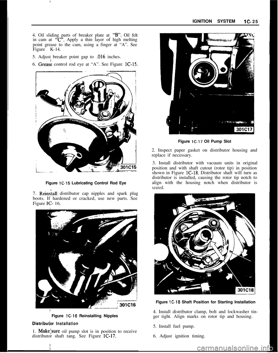
6. Grease control rod eye at “A”. See Figure lC-15.
Figure lC-15 Lubricating Control Rod Eye
7. Rein&all distributor cap nipples and spark plug
boots. If hardened or cracked, use new parts. See
Figure
l!C- 16.
/ Figure lC-16 Reinstalling Nipples
Distribu
2. Inspect paper gasket on distributor housing and
replace if necessary.
3. Install distributor with vacuum units in original
position and with shaft cutout (rotor tip) in position
shown in Figure lC-18. Distributor shaft will turn as
distributor is installed, causing the rotor tip notch to
align with the housing notch when distributor is
seated.Figure
1C-18 Shaft Position for Starting Installation
4. Install distributor clamp, bolt and lockwasher tin-
ger tight. Align marks on rotor tip and housing.
5. Install fuel pump.
6. Adjust ignition timing.
Page 51 of 625
i
1 D- 301973 OPEL SERVICE MANUAL
6. Make sure all electrical accessories are turned (lff.
Start engine with battery post adapter switch closed;
open switch as soon as engine
iS: started.
7. Adjust engine speed to 2500 RPM.
8. Turn tester control knob to “LOAD” position
aid
adjust knob to obtain highest possible ammeter r&d-
ing. Output must be 30 amperes minimum. If
outcut
is okay, proceed to voltage regulator test below. j
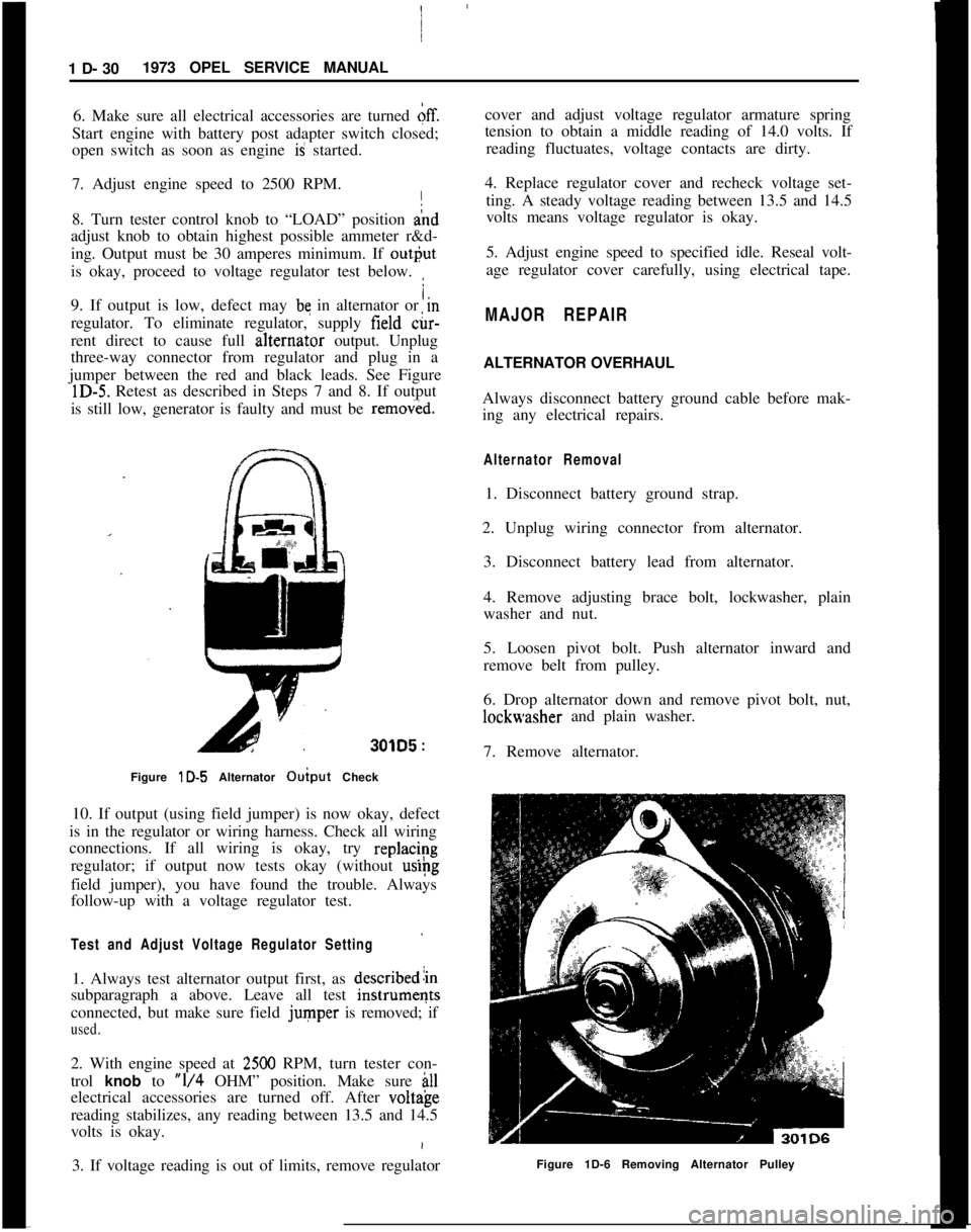
/.9. If output is low, defect may be in alternator or m
regulator. To eliminate regulator, supply field &-
rent direct to cause full alternat,or output. Unplug
three-way connector from regulator and plug in a
jumper between the red and black leads. See Figure
lD-5. Retest as described in Steps 7 and 8. If output
is still low, generator is faulty and must be
remov&d.
301D5 :
Figure lD-5 Alternator Ouiput Check I
10. If output (using field jumper) is now okay, defect
is in the regulator or wiring harness. Check all wiring
connections. If all wiring is okay, try
replac/~g
regulator; if output now tests okay (without
uslpg
field jumper), you have found the trouble. Always
follow-up with a voltage regulator test.
Test and Adjust Voltage Regulator Setting
1. Always test alternator output first, as describedlin
subparagraph a above. Leave all test
instrumeqts
connected, but make sure field
jumper is removed; if
used.
2. With engine speed at 2500 RPM, turn tester con-
trol
knob to “l/4 OHM” position. Make sure ill
electrical accessories are turned off. After volt&e
reading stabilizes, any reading between 13.5 and 14.5
volts is okay.
3. If voltage reading is out of limits, remove regulator cover and adjust voltage regulator armature spring
tension to obtain a middle reading of 14.0 volts. If
reading fluctuates, voltage contacts are dirty.
4. Replace regulator cover and recheck voltage set- ting. A steady voltage reading between 13.5 and 14.5
volts means voltage regulator is okay.
5. Adjust engine speed to specified idle. Reseal volt-
age regulator cover carefully, using electrical tape.
MAJOR REPAIR
ALTERNATOR OVERHAUL
Always disconnect battery ground cable before mak-
ing any electrical repairs.
Alternator Removal
1. Disconnect battery ground strap.
2. Unplug wiring connector from alternator. 3. Disconnect battery lead from alternator.
4. Remove adjusting brace bolt, lockwasher, plain
washer and nut.
5. Loosen pivot bolt. Push alternator inward and
remove belt from pulley.
6. Drop alternator down and remove pivot bolt, nut,
lockwasher and plain washer.
7. Remove alternator.
Figure 1D-6 Removing Alternator Pulley
Page 55 of 625
1 D- 34 1973 OPEL SERVICE MANUAL!
I
one direction, but should not light at all in the otlier
direction. Diodes in each set of three should p&s
current and block current in the ‘same directions
Asthe others in the set. See Figure lD-21.
Removing Diodes/
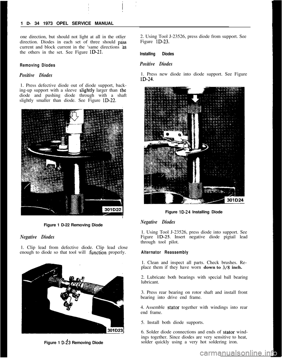
Positive Diodes1. Press defective diode out of diode support, back-
ing-up support with a sleeve sliglitly larger than the
diode and pushing diode through with a shaft
slightly smaller than diode. See Figure lD-22.;
Figure 1 D-22 Removing Diode
Negative Diodes1. Clip lead from defective diode. Clip lead close
enough to diode so that tool will .function properly.
Figure 1 D-d3 Removing Diode2. Using Tool J-23526, press diode from support. See
Figure lD-23.
Installing Diodes
Positive Diodes1. Press new diode into diode support. See FigurelD-24.
Figure lD-24 Installing Diode
Negative Diodes1. Using Tool J-23526, press diode into support. See
Figure lD-25. Insert negative diode pigtail lead
through tool pilot.
Alternator Reassembly1. Clean and inspect all parts. Check brushes. Re-
place them if they have worn down to
3/8 inch.
2. Lubricate both bearings with special ball bearing
lubricant.
3. Press rear bearing on rotor shaft and install front
bearing into drive end frame.
4. Assemble stator together with windings into rear
end frame.
5. Install both diode supports.
6. Solder diode connections and ends of stator wind-
ings together. Since diodes are very sensitive to heat,
solder quickly using a very hot soldering iron.
Page 56 of 625
CHARGING SYSTEMlD- 35
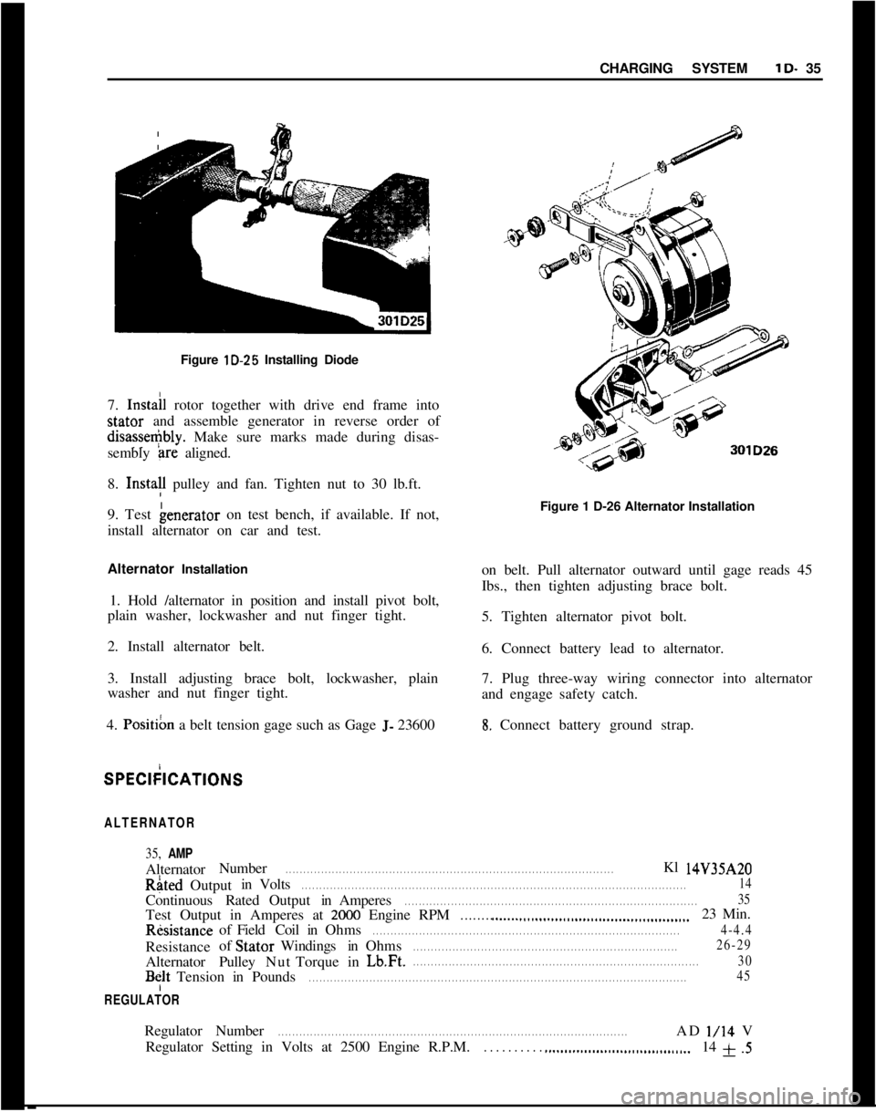
’Figure lD-25 Installing Diode
I
7. Instail rotor together with drive end frame intostator and assemble generator in reverse order ofdisasse+bly. Make sure marks made during disas-
sembly
+-ire aligned.
8. Insta!l pulley and fan. Tighten nut to 30 lb.ft.
9. Test benerator on test bench, if available. If not,
install alternator on car and test.
Alternator Installation
1. Hold /alternator in position and install pivot bolt,
plain washer, lockwasher and nut finger tight.
2. Install alternator belt.
3. Install adjusting brace bolt, lockwasher, plain
washer and nut finger tight.
4.
Posit& a belt tension gage such as Gage J- 23600Figure 1 D-26 Alternator Installation
on belt. Pull alternator outward until gage reads 45
Ibs., then tighten adjusting brace bolt.
5. Tighten alternator pivot bolt.
6. Connect battery lead to alternator.
7. Plug three-way wiring connector into alternator
and engage safety catch.8. Connect battery ground strap.SPECkICATIONS
ALTERNATOR
35, AMPAlternatorNumberRated
. . . . . . . . . . . . . . . . . . . . . . . . . . . . . . . . . . . . . . . . . . . . . . . . . . . . . . . . . . . . . . . . . . . . . . . . . . . . . . . . . . . . . . . . . . . .Kl 14V35AZOOutputinVolts
. . . . . . . . . . . . . . . . . . . . . . . . . . . . . . . . . . . . . . . . . . . . . . . . . . . . . . . . . . . . . . . . . . . . . . . . . . . . . . . . . . . . . . . . . . . . . . . . . . . . . . . . . . . .14ContinuousRatedOutputinAmperes
. . . . . . . . . . . . . . . . . . . . . . . . . . . . . . . . . . . . . . . . . . . . . . . . . . . . . . . . . . . . . . . . . . . . . . . . . . . . . . . . . .35Test Output in Amperes at
2000 Engine RPM. . . . . . . . ..__.._...........................................23 Min.RksistanceofFieldCoilinOhms
. . . . . . . . . . . . . . . . . . . . . . . . . . . . . . . . . . . . . . . . . . . . . . . . . . . . . . . . . . . . . . . . . . . . . . . . . . . . . . . . . . . . . .4-4.4Resistanceof StatorWindingsinOhms
. . . . . . . . . . . . . . . . . . . . . . . . . . . . . . . . . . . . . . . . . . . . . . . . . . . . . . . . . . . . . . . . . . . . . . . . . .26-29AlternatorPulleyNutTorqueinLb.Ft.
. . . . . . . . . . . . . . . . . . . . . . . . . . . . . . . . . . . . . . . . . . . . . . . . . . . . . . . . . . . . . . . . . . . . . . . . . . . . . . . .30
BfltTensioninPounds. . . . . . . . . . . . . . . . . . . . . . . . . . . . . . . . . . . . . . . . . . . . . . . . . . . . . . . . . . . . . . . . . . . . . . . . . . . . . . . . . . . . . . . . . . . . . . . . . . . . . . . . . .45
REGULATORRegulatorNumber
. . . . . . . . . . . . . . . . . . . . . . . . . . . . . . . . . . . . . . . . . . . . . . . . . . . . . . . . . . . . . . . . . . . . . . . . . . . . . . . . . . . . . . . . . . . . . . . . . .ADl/14V
Regulator Setting in Volts at 2500 Engine R.P.M.
. . . . . . . . . . ..___................................14 f .5
Page 58 of 625
WINDSHIELD WIPERSlE- 37WINDSHEILD WIPERS
ALL MODELS
CONTENTS
Subject
DESCRIPTION AND OPERATION:
Windshield Wiper Motor. . . . . . . . . . . . . . . . . . . . . . . . . . . . . . . . . . . . . . . . . . . . . . .DIAGNOSIS:
Windshield Wiper
. . . . . . . . . . . . . . . . . . . , , . . . . . . . . . . . . . . . . . . . . . . . . . . . . . . . . . . . . . . . . .MAINTENANCE AND ADJUSTMENTS: (Not
Applicable)
MAJOR REPAIR:Wiper Transmission
- 1900 and Manta. . . . . . . . . . . . . . . . . . . .W/per Transmission
- GT. . . . . a.* . . . . . . . . . . . . . . . . . . . . . . . . . . . . . . . . . . . . . . . .Disassembly of Wiper Motor
. . . . . . . . . . . . . . . . . . . . . . . . . . . . . . . . . . . . . . . .Cleaning and Inspection of Parts
. . . . . . . . . . . . . . . . . . . . . . . . . . . . . . .Assembly of Wiper Motor
. . . . . . . . . . . . . . . . . . . . . . . . . . . . . . . . . . . . . . . . . . . . . .Installation
. . . . . . . . . . . . . . . . . . . . . . . . . . . . . . . . . . . . . . . . . . . . . . . . . . . . . . . . . . . . . . . . . . . . . . . . . . . .SPECIFICATIONS:
GeneralSpecifications
. . . . . . . . . . . . . . . . . . . . . . . . . . . . . . . . . . . . . . . . . . . . . . . . . . . . . .Torque Specifications
. . . . . . . a.. . . . . . . . . . . . . . . . . . . . . . . . . . . . . . . . . . . . . . . . . . . . .
DESCRIPTIOfV AND OPERATION
GENERAL;DESCRlPTlDNThe two-sbeed wiper consists of a round shaped per-
manent magnet type motor and speed reduction gear
box. IOPERATldN
=The wipei motor is controlled through a dash
mounted &itch on all cars. The Rallye and GT, in
addition tb the dash mounted switch, also have a
switch moimted in conjunction with the windshield
washer fodt pump. Depressing the washer pump will
allow the bipers to operate while the pump is de-
pressed. i
DIAGNO;SIS
PRELIMINj9RY INSPECTION
1. Make
c&in of firm wire connections at wiper
motor fuse block and wiper switch.
Page No.
1 E-37
1 E-37E-38
E-38
E-40
E-41
E-4 1E-42
1 E-43
1 E-432. Check to see that the fuse is not blown.
3. Be sure wiper motor is not loose on fire wall.
4. With the yellow wire disconnected from terminal
No. 53 on the
wi@er motor, turn the ignition switch
and wiper switch to the on position and check volt-
age available to the wiper motor. There should be 12
volts available at the durple wire with a properly
charged battery.
Checking Wiper Operation1. Turn ignition switch on and engage wiper switch
to see if wiper motor will operate.
2. If wiper action is slow or inoperative, turn swit-
ches off and detach wiper control
inn from crank
arm.3. Operate wiper manually checking for excessive
bind in linkage. Correct if necessary.