oil pressure OPEL GT-R 1973 Service Manual
[x] Cancel search | Manufacturer: OPEL, Model Year: 1973, Model line: GT-R, Model: OPEL GT-R 1973Pages: 625, PDF Size: 17.22 MB
Page 17 of 625
IoC-91973 OPEL SERVICE MANUAL
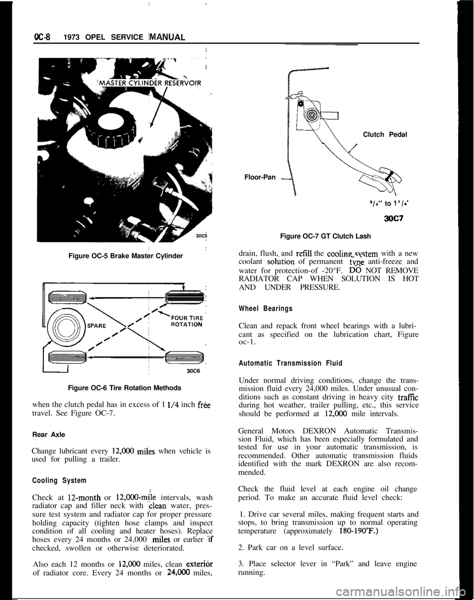
Figure OC-5 Brake Master Cylinder
I
Figure OC-6 Tire Rotation Methods
when the clutch pedal has in excess of 1
l/4 inch fr&
travel. See Figure OC-7.
Rear Axle
Change lubricant every
12,ooO miies when vehicle is
used for pulling a trailer.
Cooling SystemCheck at 12-month or
12,000~mile intervals, wash
radiator cap and filler neck with clean water, pres-
sure test system and radiator cap for proper pressure
holding capacity (tighten hose clamps and inspect
condition of all cooling and heater hoses). Replace
hoses every 24 months or 24,000 ,miles or earlier :if
checked, swollen or otherwise deteriorated.
Also each 12 months or
12,ooO miles, clean exteribr
of radiator core. Every 24 months or
24,OCO miles,Floor-Pan
-Clutch Pedal
Figure OC-7 GT Clutch Lash
drain, flush, and refill the cooline svstem with a new
coolant so&ion of permanent
6~; anti-freeze and
water for protection-of -20°F.
D-6 NOT REMOVE
RADIATOR CAP WHEN SOLUTION IS HOT
AND UNDER PRESSURE.
Wheel BearingsClean and repack front wheel bearings with a lubri-
cant as specified on the lubrication chart, Figure
oc-1.
Automatic Transmission FluidUnder normal driving conditions, change the trans-
mission fluid every 24,000 miles. Under unusual con-
ditions such as constant driving in heavy city traffic
during hot weather, trailer pulling, etc., this service
should be performed at
12,COO mile intervals.
General Motors DEXRON Automatic Transmis-
sion Fluid, which has been especially formulated and
tested for use in your automatic transmission, is
recommended. Other automatic transmission fluids
identified with the mark DEXRON are also recom-
mended.
Check the fluid level at each engine oil change
period. To make an accurate fluid level check:
1. Drive car several miles, making frequent starts and
stops, to bring transmission up to normal operating
temperature (approximately
180-190’F.)2. Park car on a level surface.
3. Place selector lever in “Park” and leave engine
running.
Page 62 of 625

WINDSHIELD WIPERSlE-41
Figurk 1 E-l 3 Cut Off Positive Brush Leads
i
Figure iE-14 Remove Negative Brush Retaining
S.X?WI
Cleaning apd Inspection of PartsWith the ekception of electrical parts and bushings,
clean all components in a cleaning solvent.
1. Check irmatare windings for ground, or open
circuit. If
b ground or open circuit is evident, the
armature must be replaced. If the armature checks
out, the c
brushes should be 6.35 to 8.47 ounces. Spring pres-
sure of worn brushes should be at least 3.5 ounces.
In case of /ower spring pressure, replace springs.
3. Check blushes for wear and replace if necessary.
Minimum brush length should be
.24’inch.4. Check d$ven gear for wear and replace if neces-
sary.
Assembly
02383. I
2. Install
d&en gear into housing3. Apply a small amount of grease to ball cavity of
driven gear and insert ball. See Figure lE-15.
Figure lE-15 Insert Ball into Driven Gear
4. Install transmission housing cover. See Figure
lE-
16.2. DRIVEN GEAR
3. CONTACT SPRINGS
4. TRANSMISSION
HOUSING COVER
Figure 1 E-l 6 Install Transmission Housing
Cover5. Solder positive brush lead(s) to brush holder(s).
Hold brush lead with needle nose pliers to prevent
solder from running up wire strands. See Figure
lE-
17.6. Install negative brush
7. Apply a small amount of grease to end of armature
shaft. Lightly oil armature shaft.
8. Insert brush springs and brushes into brush hold-
ers. Slide armature into housing, taking care not to
damage brushes.
Page 64 of 625

WINDSHIELD WIPERSlE-43SPEhFlCATlONS
IGENEPAL SPECIFICATIONSiRated Voltage .
..__.,,,.,,,......................................,.,,... ~ __..__...__...._..................................... 12 VDC
,Test Voltage ___..................................................,...................,..,..................................... 13 VDC
Current Draw (Amps)
;No Load_, Low Speed
..__...__..__..,_,,..,,,.,,,,..,....................,,.................................................................. 1.5
I Hieh
SDeed .___,,...,,..,,._.._..............,...............................,,,..,,,.............................................. 2.2lLock:d
’
:Low Speed ___.,._,,,..,,,....................................,,.........,,..,,,.,,,,..................,,,........................... 16
,
High Speed . . . . . . . ..___.._........................................................................................................... 17
~Minimum Commutator Diameter __.................,,,,........................................................... .86 in.
‘Brush Spring Pressure
:New Brush
. . . . . . .._...__...................................................................................... 6.35 to 8.47 oz.Used Brush
..__,,,...,,.,,..................,...............................,,.,,,,.,,....................... 3.5 oz. minimum‘MinimumBrushLength
. . . . . . . . . . . . . . . . . . . . . . . . . . . . . . . . . . . . . . . . . . . . . . . . . . . . . . . . . . . . . . . . . . . . . . . . . . . . . . . . . . . . . . . . . . . . . . . . . .24in.The windshield wiper motor instead of field coils has a permanent magnet
(oxide magnet). This motor design is sturdier and consumes less current.TORQirE SPECIFICATIONS
‘CrankArmtoMotorDriveShaft. . . . . . . . . . . . . . . . . . . . . . . . . .70to87in.lbs.iper Motor to Cowl
,
,.,,,.,,,,..,,............,..,,.,,.........................................14 to 17 in.lbs.
Page 67 of 625
1F. 46 1973 OPEL SERVICE MANUAL
’
/
Headlight High-Low Beam Control and Passing:
SignalI
When the headlights have been switched on, high
and low beam selection is made by raising the direc-
tional signal lever toward steering wheel. Each
ti&the lever is raised, beam position, will change.
When the headlights are not on, a flashing headlight
signal may be given by raising and lotiering the di-
rectional signal lever. With the headlights on and
inlow beam position, raising and lowering the direc-
tional signal lever will also cause the headlights to
flash.
Fog Light SwitchAll Rallye models are equipped with two white f?g
lights mounted below the front bumper.
The fog light toggle switch is located on the
insty-ment cluster to the left of the temperature and
fuelgauge cluster.
/
The fog lights can be turned off at any time by the
toggle switch, but can only be tyrned on when: :
1. The ignition switch on or the
?gine running.!
2. The fog light toggle switch lower half is pushed
in.3. The parking lights and/or low beam headlights
are
OKThe fog lights are automatically turned off if the
ignition switch is on and the headlights are switched
to high beam position.
Courtesy LightThe courtesy light illuminates the interior of the Car
when any door is opened. The courtesy light can also
be turned on with all doors closed by tilting the l&s.
GT Headlamp MechanismThe concealed headlamps are moved mechanically.
Pushing actuating lever on left side of console opens
headlamps and pulling lever closes headlamps. Two
(2) meshing gear segments convert the movement, of
the lever to a rotation of 180 degrees. The pivots of
the headlamps lie below the centerline so that with
headlamps in closed position, the headlamp housing
is flush with front sheet metal. Refer to Group 110,
Section “F”, for service procedures on the GT head-
lamp mechanism.
A white indicator lamp in the instrument panel lights
if the headlamps are not completely opened lorclosed The switches of the headlamp electrical sys-
tem are located behind the left headlamp operating,
mechanism.
MAINTENANCE AND ADJUSTMENTSHEADLAMP AIMING
The headlamps must be properly aimed in order to
obtain maximum road illumination and safety that
has been built into the headlighting equipment. With
the Guide T-3 type sealed beam units, proper aiming
is even more important because the increased range
and power of this lamp make even slight variations
from recommended aiming hazardous to approach-
ing motorists. The headlamps must be checked for
proper aim whenever a sealed beam unit is replaced
and after an adjustment or repairs of the front end
sheet metal assembly.
Regardless of method used for checking headlamp
aim, car must be at normal weight, that is, with gas,
oil, water, and spare tire. Tires must be uniformly
inflated to specified pressure. If car will regularly
carry an unusual load in rear compartment, or a
trailer, these loads should be on car when headlamps
are checked. Some States have special requirements
for headlamp aiming adjustment, and these require-
ments should be known and observed.
Horizontal and vertical aiming of each seal beam
unit is provided by two adjusting screws which move
the mounting ring in the body against the tension of
the coil spring. There is no adjustment for focus,
since the sealed beam unit is set for proper focus
during manufacturing assembly.
MAJOR REPAIRHEADLIGHT SWITCH
- OPEL 1900. MANTA
Removal1. Remove instrument cluster cover panel. See Sec-
tion H.
2. Compress retaining springs and pull switch out.
See Figure 1 F-
1.3. Pull multiple socket off switch.
Installation
1: Plug multiple socket in switch and push switch in
panel until clips lock in place.
2. Replace instrument cover and secure with two (2)
screws.
Page 77 of 625
:lG- 56 1973 OPEL SERVICE MANUAL
I
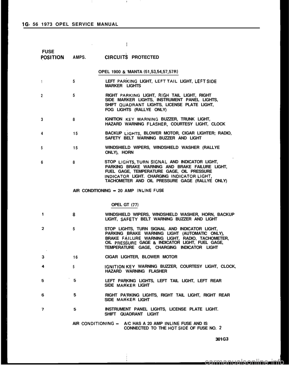
FUSEqOSlTlON
1
2
3
4
5
6AMPS.
5
5
8
15
15
8ClRClJlT$ PROTECTED
OPEL 1900
& ‘MANTA (51,53,54,57,57R)
LEFT PARkING LIGHT,
LEFTTAIL LIGHT, LEFTSIDE
MARKER LIGHTS
RIGHT PApKING LIGHT, RIGH TAIL LIGHT, RIGHT
SIDE MARKER LIGHTS, INSTRUMENT PANEL LIGHTS,
SHIFT GUADRANT LIGHTS, LICENSE PLATE LIGHT,
FOG LIGHTS (RALLYE ONLY)
IGNITION IKEY
WARNIN BUZZER, TRUNK LIGHT,
HAZARD WARNING FLA,SHER, COURTESY LIGHT, CLOCK
BACKUP L’IGHTS, BLOWER MOTOR, CIGAR LIGHTER; RADIO,
SAFETY BELT WARNING BUZZER AND LIGHT
WINDSHIELD WIPERS, WINDSHIELD WASHER (RALLYE
ONLY), HORN
STOP LIGtiTS,TURN
SlGsNAL AND INDICATOR LIGHT,
PARKING BRAKE WARNING AND BRAKE FAILURE LIGHT,
FUEL GAGE, TEMPERATURE GAGE, OIL PRESSUREINDICATGR LIGHT. CHARGING INDICATOR~LIGHT,
TACHOMETER AND OIL PRESSURE GAGE (RALLYE ONLY)
AIR CONDITIONING
- 20 AMP INLINE F:USE
8
5
16
5OPEL GT
(77)WINDSHIELD WIPERS, WINDSHIELD WASHER, HORN, BACKUP
LIGHT, SP;FETY BELT WARNING BUZZER AND LIGHT
STOP LIGHTS, TURN SIGNAL AND INDICATOR LIGHT,
PARKING BRAKE WARNING LIGHT (AUTOMATIC ONLY),
BRAKE FAILURE WARNING LIGHT, RADIO, TACHOMETER,
OIL PRESiURE GAGE
& INDICATOR LIGHT, FUEL GAGE,
TEMPERATURE GAGE, CHARGING INDICATOR LIGHT
CIGAR LIGHTER, BLOWER MOTORIGNITION~KEY WARNING BUZZER, COURTESY LIGHT, CLOCK,
HAZARD WARNING FLASHER
LEFT PARKING LIGHTS, LEFT TAIL LIGHT, LEFT REAR
SIDE MAdKER LIGHT
RIGHT PA’RKING LIGHTS, RIGHT TAIL LIGHT, RIGHT REAR
SIDE MAdKER LIGHT
INSTRUMENT PANEL LIGHTS, LICENSE PLATE LIGHT.
SHIFT QUADRANT LIGHT
AIR CON,DlTlONlNG
-A/C HAS A 20 AMP INLINE FUSE AND IS
CONNECTED TO THE HOTSIDE OF FUSE NO. 23OlG3
Page 86 of 625
GAUGES
CONTENTS
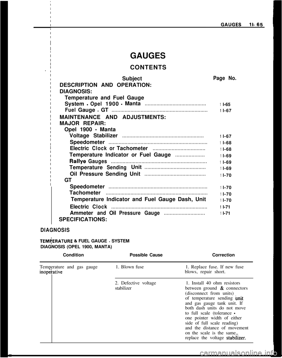
Subject
DESCRIPTION AND OPERATION:
DIAGNOSIS:
Temperature and Fuel Gauge
System-Opel1900-Manta. . . . . . . . . . . . . . . . . . . . . . . . . . . . . . . . . . . . . . . . . .
FuelGauge-GT. . . . . . . . . . . . . . . . . . . . . . . . . . . . . . . . . . . . . . . . . . . . . . . . . . . . . . . . . . . . . . . . . .MAINTENANCE AND ADJUSTMENTS:
MAJOR REPAIR:
Opel 1900
- Manta
Voltage Stabilizer
. . . . . . . . . . . . . . . . . . . . . . . . . . . . . . . . . . . . . . . . . . . . . . . . . . . . . . . .Speedometer
. . . . . . . . . . . . . . . . . . . . . . . . . . . . . . . . . . . . . . . . . . . . . . . . . . . . . . . . . . . . . . . . . . . .Electric
ClockorTachometer. . . . . . . . . . . . . . . . . . . . . . . . . . . . . . . . . . . .Temperature Indicator or Fuel Gauge
. . . . . . . . . . . . . . . . . . . .Rallye
Gauges. . . . . . . . . . . . . . . . . . . . . . . . . . . . . . . . . . . . . . . . . . . . . . . . . . . . . . . . . . . . . . . . . .Temperature
SendingUnit. . . . . . . . . . . . . . . . . . . . . . . . . . . . . . . . . . . . . . . . . .Oil Pressure Sending Unit
. . . . . . . . . . . . . . . . . . . . . . . . . . . . . . . . . . . . . . . . . .GT
Speedometer
. . . . . . . . . . . . . . . . . . . . . . . . . . . . . . . . . . . . . . . . . . . . . . . . . . . . . . . . . . . . . . . . . . . .Tachometer
. . . . . . . . . . . . . . . . . . . . . . . . . . . . . . . . . . . . . . . . . . . . . . . . . . . . . . . . . . . . . . . . . . . . . .Temperature Indicator and Fuel Gauge Dash, Unit
Electric
Clock. . . . . . . . . . . . . . . . . . . . . . . . . . . . . . . . . . . . . . . . . . . . . . . . . . . . . . . . . . . . . . . . . .Ammeter
andOilPressureGauge. . . . . . . . . . . . . . . . . . . . . . . . . . . .SPECIFICATIONS:
DIAGNOSISITEM(ERATURE
& FUEL GAUGE - SYSTEM
DIAGNOSIS (OPEL 1900, MANTA)
/
ConditionPossible Cause
I
Page No.
1l-65
1l-67
1l-67
1l-68
1l-68
1l-69
1l-69
1l-69
1l-70
1l-70
1l-70
1l-70
1l-71
1l-71
Correction
Temperature and gas gaugeinopetative1. Blown fuse1. Replace fuse. If new fuse
blows, repair short.
2. Defective voltage
stabilizer1. Install 40 ohm resistors
between ground
& connectors
(disconnect from units)
of temperature sending imit
and gas gauge tank unit. If
both dash units do not move
to full scale (tolerance
-one pointer width of either
side of full scale reading)
and the distance of movement
on the scale is the same,,
replace the voltage stabdner.
Page 91 of 625

lb 70 1973 OPEL SERVlCE!MANUAL
Removing Oil Pressure Sending Upit1. Disconnect wire from sending
Fit.2. Unscrew oil pressure sending
u?it from block. St&Figure
11-7./
Figure
11.7 - Oil Pressure Sending Unit
Installation1. Replace oil pressure sending unit into block.
2. Connect wire to unit.
Figure 1 l-8 Rear View of SpeedometerI
Removal of Speedometer1. Remove instrument housing.
2.Remove speedometer. See Figure 11-9 1.
Installation
1.Install speedometer.
2.Install instrument housing, paragraph 11-71.per
Removal of Tachometer1. Remove instrument housing.
2.Remove tachometer.
3.Disconnect electrical wires. See Figure 11-9.
Figure
11-9 Rear View of Tachometer
Installation1. Connect wires.
2. Install tachometer.
3. Install instrument cluster.
Removal of Temperature Indicator and Fuel GaugeDash Unit
1. Remove instrument housing.
2. Remove temperature indicator and fuel gauge
dash unit.
3. Disconnect electrical wires. See figure
11-10.
Page 92 of 625

I
IGAUGESll- 71
Figure 1
IL10 Rear View of Temperature Indicator and
I
IFuel Gauge Dash Unit
I
Install&m1. Connekt wires and install unit.
2. Install! instrument cluster housing.
I
Removal
\of Electric Clock
1.
Remoie instrument housing.
Figuy 1 I-1 1 Rear View of Electrical Clock
I2. Remove electrical clock.
3. Disconnect electrical wires. See Figure
11-I I.
Installation
1. Install clock and connect wires.
2. Install instrument cluster housing.
Removal of Ammeter and Oil Pressure Gauge
1. Remove instrument housing.
2. Remove ammeter and oil pressure gauge.
3. Disconnect electrical wires. See Figure
11-12.Figure 1 I-1 2 Rear View of Ammeter and Oil Pressure
GaugeInstallation
1. Connect wires to ammeter and oil pressure gauge
and install.
2. Install instrument cluster housing.
Page 126 of 625

GENERAL INFORMATIONZA- 3
ded with rubber, and volatile cleaners are generally
solvents for rubber. The application of too much
cleaner may destroy these rubber pads. Do not use
volatile cleaners on vinyl coated fabrics.
Procedure For Cleaning
Vinyl Fabrics With Synthetic Detergents
1. Make a solution of the synthetic detergent in luke-
warm water, working up a thick, frothy suds.
2. With a clean cloth or sponge, dampened with
lukewarm water, apply suds only to the surface of the
upholstery using light to medium pressure, repeating
several times, applying more suds with a clean por-
tion of the cloth or sponge.
3. With a second clean cloth, dampened with luke-
warm water, rub over the area with medium pressure
to remove excess detergent and loose material.
4. With a clean dry cloth, wipe off all excess mois-
ture. A vacuum cleaner may also be used.
5. Allow the upholstery to dry partially; then repeat
the above treatment if necessary to remove stain.
6. When the upholstery is satisfactorily cleaned, al-
low to dry completely before using.
Instructions for the Removal of
Specific Stains From Automotive
Upholstery Materials
Some types of stains and soilage, including blood,
ink, chewing gum, etc., require special consideration
for satisfactory results. For thkse, and other stains,
specific instructions are outlined in succeeding para-
graphs. It must be expected, particularly where wa-
ter treatment is specified, that discoloration and
finish disturbance may occur. In some cases fabric
disturbance may be considered preferable to the stain
itself. By following the procedures outlined below,
reasonably satisfactory results can be expected.
1. Bafrery Acids. Apply ordinary household am-
monia water with a brush or cloth to the affected
‘area, saturating it thoroughly. Permit the ammonia
water to remain on the spot about a minute, so that
it will have ample time to neutralize the acid. Then
rinse the spot by rubbing with a clean cloth saturated
with cold water.
This treatment will suffice for both old and new
stains. However, no type of treatment will repairdamage.to fibers resulting from the actidn of the
acids on the fibers particularly after the spot has
dried.
2.
Blood. Do not use hot water or soap and wateron blood stains since they will set the stain, thereby
making its removal practically impossible.
Rub the stain with a clean cloth saturated with cold
water until no more of the stain will come out. Care
must be taken so that clean portions ofcloth are used
for rubbing the stain.
This treatment should remove all of the stain. If it
does not, apply a small amount of household am-
monia water to the stain with a cloth or brush. After
a lapse of about one minute, continue to rub the stain
with a clean cloth dipped in clear cold water.
If the stain remains after the use of water and am-
monia, a thick paste of corn starch and cold water
may be applied to the stained area. Allow the paste
to remain until it has dried and absorbed the stain.
Then pick off the dry starch. Brush the surface to
remove starch particles that remain. For heavy
stains, several applications of starch paste may be
necessary.3. Candy. Candy stains, other than candy contain-
ing chocolate, can be removed by rubbing the af-
fected area with a cloth soaked with very hot water.
If the stain is not completely removed, rub area
lightly (after drying) with a cloth wet with a volatile
cleaner. This will usually remove the stain.
Candy stains resulting from cream and fruit-filled
chocolates can be removed more easily by rubbing
with a cloth soaked in lukewarm soap-suds (mild
neutral soap) and scraping, while wet, with a dull
knife. This treatment is followed with a rinsing by
rubbing the spot with a cloth dipped in cold water.
Stains resulting from chocolate or milk chocolate can
be removed by rubbing the stain with a cloth wet
with lukewarm water. After the spot is dry, rub it
lightly with a cloth dipped in a volatile cleaner.
4. Chewing Gum. Harden the gum with an ice cube,
and scrape off particles with a dull knife. If gum
cannot be removed completely by this method, mois-
ten it with a volatile cleaner and work it from the
fabric with a dull knife, while gum is still moist.
5. Fruit, Fruit Stains, Liquor and Wine. Practicallyall fruit stains can be removed by treatment with very
hot water. Wet the stain well by applying hot water
to the spot with a clean cloth. Scrape all excess pulp,
if present, off the fabric with a dull knife; then rub
vigorously with a cloth wet with very hot water. If
the stain is very old or deep, it may be necessary to
pour very hot water directly on the spot, following
this treatment with the scraping and rubbing. Direct
application of hot water to fabrics is not recom-
mended for general use since discoloration usually
results.
If the above treatments do not remove stain, allow
Page 234 of 625
PROPELLER SHAFT AND CENTRAL JOINT4A- 3MAJOR REPAIR
PROPELLER SHAFT REMOVAL AND
INSTALLATION
Removal
1. Raise rear of car and support on jack stands at rear
jack brackets.
2. Disconnect parking brake cable equalizer from
rod.3. On the Opel
1900 and Manta, unhook parking
brake cable from floor panel.
4. On the Opel 1900 and Manta, unhook exhaust
system and let it down.
5. Mark the mating parts of the U-joint and the drive
pinion extension shaft flange.
6. Loosen bolt locks and remove bolts or nuts.
7. Work propeller shaft slightly forward, lower rear
end of shaft and slide assembly rearward. Remove
thrust spring from front of propeller shaft.
S. Install plug in transmission extension housing to
prevent loss of lubricant.
installation
CAUTION:
Fasteners in the foJlowing steps are impor-
tant attaching parts in that they could affect the
performance of
vital components and systems, and-
/or could
result in major repair expense. They must
be replaced with one of the
samepart number or with
an equivalent part
ifreplacement becomes oecessary.
Do not use a replacement part of lesser quality or
substitute design. Torque values must be used as
specirid during reassembly to assure proper reten-
tion of these parts.1. Remove plug from rear of transmission.
2. Slide thrust spring onto transmission output shaft
and slide propeller shaft through the oil seal and onto
the transmission output shaft. Make certain trans-
mission rear seal is not damaged.
3. Align rear universal joint and pinion flange locat-
ing marks and secure with respective bolts and lock
plates. Torque bolts to 11
lb.ft. Bend lock plate tangs
to secure bolts or nuts.
4. Connect parking brake cable equalizer to brake
rod and adjust to specifications.
5. On the Opel 1900 and Manta connect parking
brake cable to floor panel.DISASSEMBLY AND ASSEMBLY OF THE
CENTRAL JOINT
Disassembly of Central Joint1. Raise and support rear of car under axle tubes.
2. Release brake line bracket from rear of torque
tube.3. Disconnect parking brake cable equalizer and re-
turn spring from brake rod.
4. On the Opel 1900 and Manta, unhook exhaust
system and let it down.
5. Mark universal joint and flange. Disconnect pro-
peller shaft from flange and support it out of the way.
6. Support torque tube with floor jack using mini-
mum pressure.
7. Remove the central joint bracket to underbody
attaching bolts.
8. Allow floor jack to lower the torque tube.
9. Disconnect torque tube from differential carrier by
removing the attaching bolts.
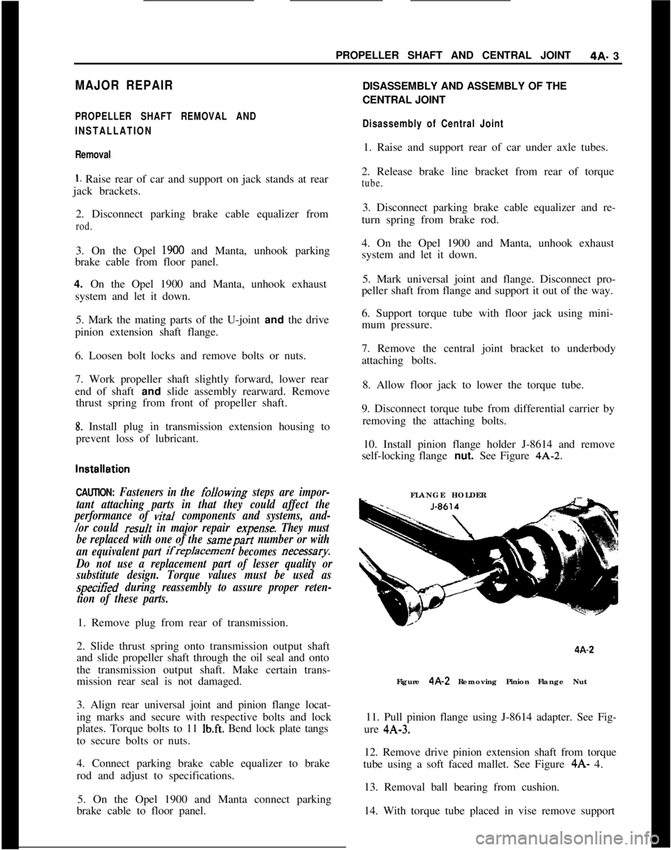
10. Install pinion flange holder J-8614 and remove
self-locking flange nut. See Figure 4A-2.
FLANGE HOLDER4A-2
Figure 4A-2 Removing Pinion Flange Nut
11. Pull pinion flange using J-8614 adapter. See Fig-
ure 4A-3.
12. Remove drive pinion extension shaft from torque
tube using a soft faced mallet. See Figure 4A- 4.
13. Removal ball bearing from cushion.
14. With torque tube placed in vise remove support