width OPEL GT-R 1973 Service Manual
[x] Cancel search | Manufacturer: OPEL, Model Year: 1973, Model line: GT-R, Model: OPEL GT-R 1973Pages: 625, PDF Size: 17.22 MB
Page 11 of 625
sOA- 1973 OPEL SERVICE MANUAL _
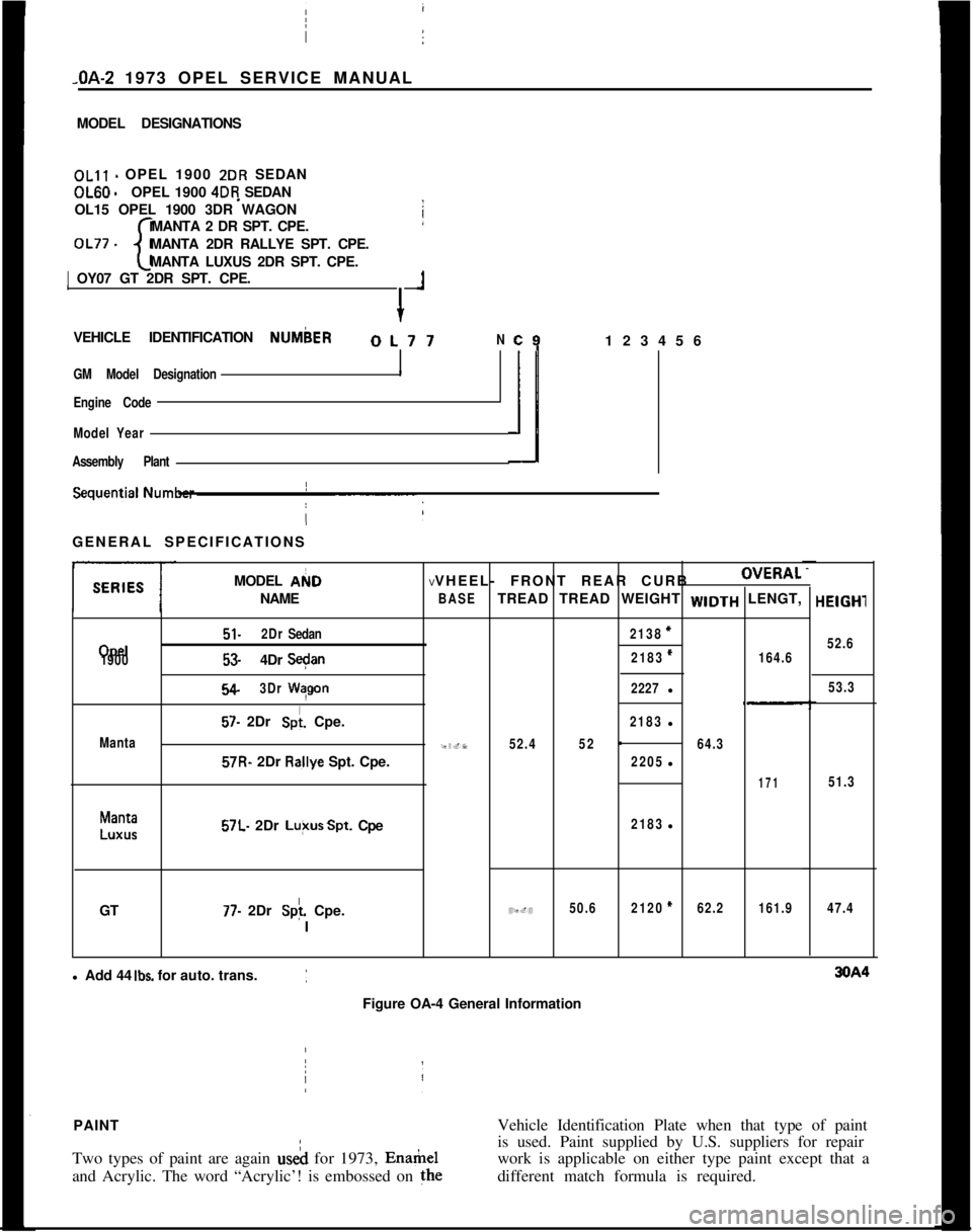
MODEL DESIGNATIONSOLll - OPEL 1900 2DR SEDANOL60
-OPEL 1900 4DR SEDAN
OL15 OPEL 1900 3DR WAGON
MANTA 2 DR SPT. CPE.
OL77 -
cMANTA 2DR RALLYE SPT. CPE.
MANTA LUXUS 2DR SPT. CPE.1 OY07 GT 2DR SPT. CPE.
+
1VEHICLE IDENTIFICATION NUMbER
OL77N
GM Model Designation
I
Engine Code
Model Year
Assembly Plant
c9123456
ilGENERAL SPECIFICATIONS
MODEL AI(ID
NAME I
Opel
1900
Manta
51.2DrSedan
53.4DrS+n
54.3DrWqgon
57. 2Dr Spi. Cpe.57R- 2Dr R&ye Spt. Cpe.
Manta
LUXUS57L. 2Dr Lu+sSpt. Cpe
GT
77. 2Dr Splf. Cpe.
IVVHEEL- FRONT REAR CURBOVERAL
BASETREAD TREAD WEIGHT WIDTH LENGT,
2138=
2183*164.6
2227l
2183l
95.752.452-64.3
2205l
171
2183l
49.450.62120*62.2161.9l Add 44
Ibs. for auto. trans.
Figure OA-4 General InformationHElGHl
52.6
53.3
51.3
47.4PAINTVehicle Identification Plate when that type of paint
Two types of paint are again useh for 1973, Enamelis used. Paint supplied by U.S. suppliers for repair
work is applicable on either type paint except that a
and Acrylic. The word “Acrylic’! is embossed on thedifferent match formula is required.
/
Page 86 of 625
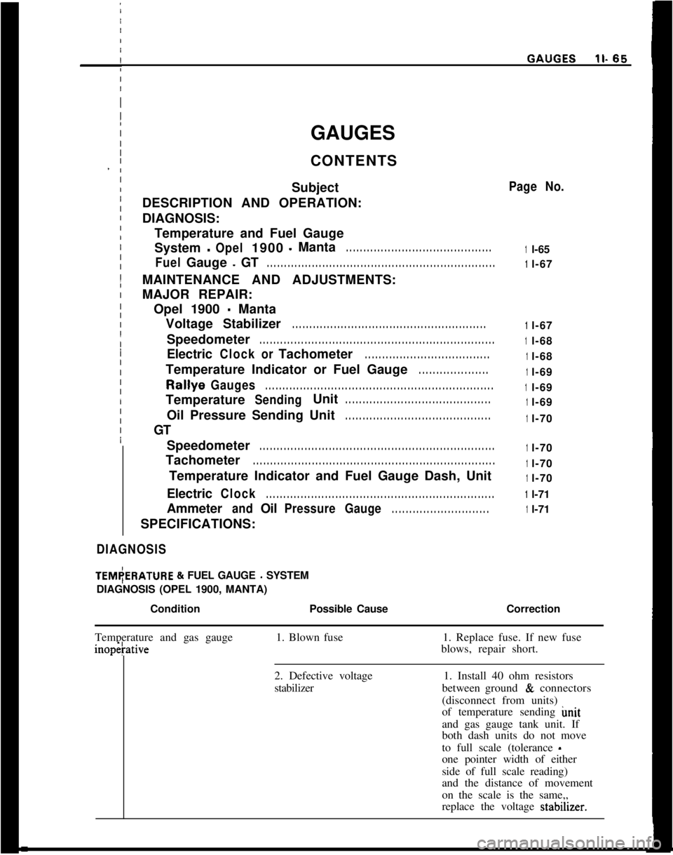
GAUGES
CONTENTS
Subject
DESCRIPTION AND OPERATION:
DIAGNOSIS:
Temperature and Fuel Gauge
System-Opel1900-Manta. . . . . . . . . . . . . . . . . . . . . . . . . . . . . . . . . . . . . . . . . .
FuelGauge-GT. . . . . . . . . . . . . . . . . . . . . . . . . . . . . . . . . . . . . . . . . . . . . . . . . . . . . . . . . . . . . . . . . .MAINTENANCE AND ADJUSTMENTS:
MAJOR REPAIR:
Opel 1900
- Manta
Voltage Stabilizer
. . . . . . . . . . . . . . . . . . . . . . . . . . . . . . . . . . . . . . . . . . . . . . . . . . . . . . . .Speedometer
. . . . . . . . . . . . . . . . . . . . . . . . . . . . . . . . . . . . . . . . . . . . . . . . . . . . . . . . . . . . . . . . . . . .Electric
ClockorTachometer. . . . . . . . . . . . . . . . . . . . . . . . . . . . . . . . . . . .Temperature Indicator or Fuel Gauge
. . . . . . . . . . . . . . . . . . . .Rallye
Gauges. . . . . . . . . . . . . . . . . . . . . . . . . . . . . . . . . . . . . . . . . . . . . . . . . . . . . . . . . . . . . . . . . .Temperature
SendingUnit. . . . . . . . . . . . . . . . . . . . . . . . . . . . . . . . . . . . . . . . . .Oil Pressure Sending Unit
. . . . . . . . . . . . . . . . . . . . . . . . . . . . . . . . . . . . . . . . . .GT
Speedometer
. . . . . . . . . . . . . . . . . . . . . . . . . . . . . . . . . . . . . . . . . . . . . . . . . . . . . . . . . . . . . . . . . . . .Tachometer
. . . . . . . . . . . . . . . . . . . . . . . . . . . . . . . . . . . . . . . . . . . . . . . . . . . . . . . . . . . . . . . . . . . . . .Temperature Indicator and Fuel Gauge Dash, Unit
Electric
Clock. . . . . . . . . . . . . . . . . . . . . . . . . . . . . . . . . . . . . . . . . . . . . . . . . . . . . . . . . . . . . . . . . .Ammeter
andOilPressureGauge. . . . . . . . . . . . . . . . . . . . . . . . . . . .SPECIFICATIONS:
DIAGNOSISITEM(ERATURE
& FUEL GAUGE - SYSTEM
DIAGNOSIS (OPEL 1900, MANTA)
/
ConditionPossible Cause
I
Page No.
1l-65
1l-67
1l-67
1l-68
1l-68
1l-69
1l-69
1l-69
1l-70
1l-70
1l-70
1l-70
1l-71
1l-71
Correction
Temperature and gas gaugeinopetative1. Blown fuse1. Replace fuse. If new fuse
blows, repair short.
2. Defective voltage
stabilizer1. Install 40 ohm resistors
between ground
& connectors
(disconnect from units)
of temperature sending imit
and gas gauge tank unit. If
both dash units do not move
to full scale (tolerance
-one pointer width of either
side of full scale reading)
and the distance of movement
on the scale is the same,,
replace the voltage stabdner.
Page 87 of 625
ll- 66 1973 OPEL SERVICE MANUALi
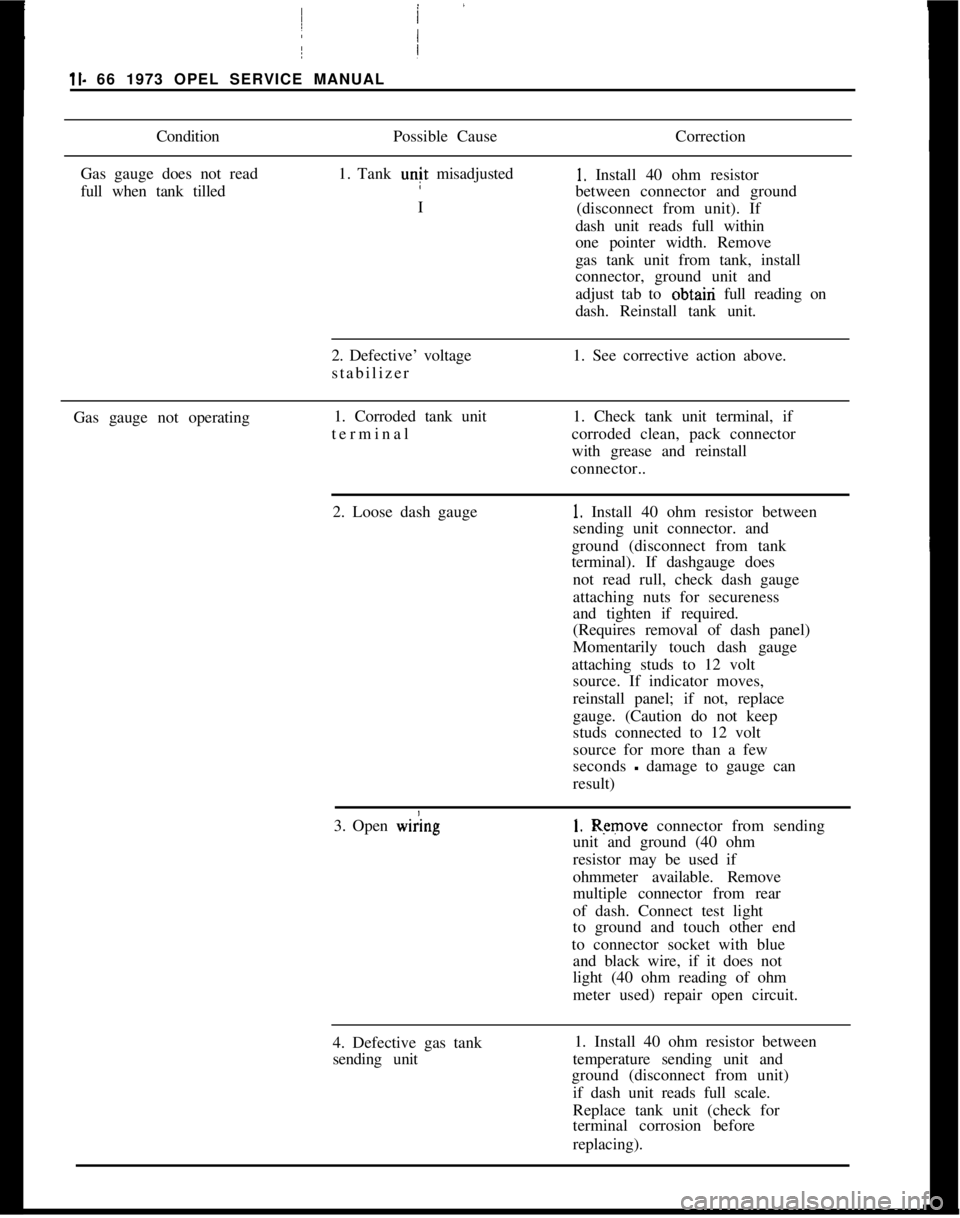
ConditionPossible CauseCorrection
Gas gauge does not read
full when tank tilled1. Tank unit misadjusted1. Install 40 ohm resistor
between connector and ground
I
(disconnect from unit). If
dash unit reads full within
one pointer width. Remove
/
Igas tank unit from tank, install
connector, ground unit and
adjust tab to obtairi full reading on
dash. Reinstall tank unit.
2. Defective’ voltage
stabilizer1. See corrective action above.
Gas gauge not operating1. Corroded tank unit
terminal I1. Check tank unit terminal, if
corroded clean, pack connector
with grease and reinstall
connector..
2. Loose dash gauge
!
1. Install 40 ohm resistor between
sending unit connector. and
ground (disconnect from tank
terminal). If dashgauge does
not read rull, check dash gauge
attaching nuts for secureness
and tighten if required.
(Requires removal of dash panel)
Momentarily touch dash gauge
attaching studs to 12 volt
source. If indicator moves,
reinstall panel; if not, replace
gauge. (Caution do not keep
studs connected to 12 volt
source for more than a few
seconds
- damage to gauge can
result)
3. Open
w&g1. Remove connector from sending
unit and ground (40 ohm
resistor may be used if
ohmmeter available. Remove
multiple connector from rear
of dash. Connect test light
to ground and touch other end
to connector socket with blue
and black wire, if it does not
light (40 ohm reading of ohm
meter used) repair open circuit.
4. Defective gas tank
sending unit1. Install 40 ohm resistor between
temperature sending unit and
ground (disconnect from unit)
if dash unit reads full scale.
Replace tank unit (check for
terminal corrosion before
replacing).
Page 227 of 625
36. 601973 OPEL SERVICE MANUAL
severe or careless driver. Rapid acceleration and de-celeration, severe application of brakes, taking turns
at excessive speed, high-speed driving, and striking
curbs or other obstructions which lead to misalign-
ment are driving habits which will shorten the life of
any tire.hiaintenance of proper inflation pressure and peri-
odic interchanging of tires to equalize wear are
within the control of the driver. Underinflation
raises the internal temperature of a tire greatly due
to the continual friction caused by the flexing of the
side walls. Tire squealing on turns is an indication of
underinflation or excessive speed on the turns. A
combination of underinflation, high road tempera-
tures, and high-speed driving will quickly ruin the
best tire made.
High speed on straight highways or expressways nor-
mally causes more rapid wear on the rear than on thefront tires, although cupping of front tires can result
if the tires are not periodically switched from wheel
to wheel. Driving turns and curves at too high a rate
of speed causes the front tires to wear much faster
than the rear tires.
An inspection of the tires, together with information
as to locality in which the car has been operated willusually indicate whether abnormal wear is due to the
operating conditions described above or to mechani-cal faults which should be corrected.
The various types of
abnormal tire wear and their
causes are described in the following paragraphs.
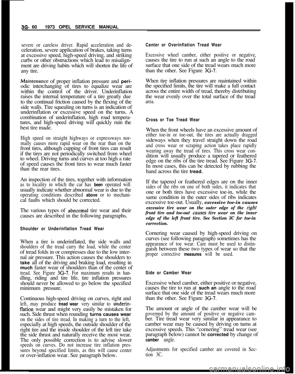
Shoulder or Underinflation Tread WearWhen a tire is underinflated, the side walls and
shoulders of the tread carry the load, while the centerof tread folds in or compresses due to the low inter-
nal air pressure. This action causes the shoulders to
take all of the driving and braking load, resulting in
much faster wear of shoulders than of the center of
tread. See Figure 3G-7. For maximum results in han-dling, riding and tire life, tire inflation pressures
should never be allowed to go below the specified
minimum pressure.
Continuous high-speed driving on curves, right and
left, may produce tread wear very similar to underin-flation wear and might very easily be mistaken for
such. Side thrust when rounding turns causes wear
on the sides of tire tread. In making a turn to the left,especially at high speeds, the outside shoulder of the
right tire and the inside shoulder of the left tire take
the side thrust and naturally receive the most wear.
The only possible correction is to advise slower
speeds on curves. Do not increase tire inflation pres-
sures beyond specified limits, as this will cause centeror over-inflation wear. See paragraph below.
Canter or Overinflation Tread Wear
Excessive wheel camber, either positive or negative,causes the tire to run at such an angle to the road
surface that one side of the tread wears much more
than the other. See Figure
3G-7.When tire inflation pressures are maintained within
the specified limits, the tire will make a full contact
across the entire width of tread, thereby distributing
the wear evenly over the total surface of the tread
area.
Cross or Toe Tread WearWhen the front wheels have an excessive amount of
either toe-in or toe-out, the tires are actually draggedsideways when they travel straight down the road
and cross wear or scraping action takes place rapidly
wearing away the tread of tires. This cross wear con-dition will usually produce a tapered or feathered
edge on the ribs of the tire tread. See Figure
3G-7.In most cases, this can be detected by rubbing the
hand across the tire tread.
If the tapered or feathered edges are on the inner
sides of the ribs on one of both sides, it indicates thatone or both tires have excessive toe-in, while the
same condition in the outer sides of ribs indicates
excessive toe-out. Usually, excessive toe-in causes
excessive tire wear on the outer edge of the right
front tire and toe-out causes tire wear on the inner
edge of the left front tire. See Section 3C for toe-in
correction.Cornering wear caused by high-speed driving on
curves (see following paragraph) sometimes has the
appearance of toe wear. Care must be used to distin-guish between these two types of wear so that the
proper corrective measures will be used.
Side or Camber WearExcessive wheel camber, either positive or negative,
causes the tire to run at such an angle to the road
surface that one side of the tread wears much more
than the other. See Figure
3G-7.The amount or angle of the camber wear will be
governed by the amount of positive or negative cam-ber. Tire tread wear very similar in appearance to
camber wear may be caused by driving on turns at
excessive speeds. This “cornering” tread wear (see
paragraph below) cannot be corrected by change of
camber angle.
Adjustments for specified camber are covered in Sec-
tion 3C.
Page 242 of 625
REAR AXLE40- 11
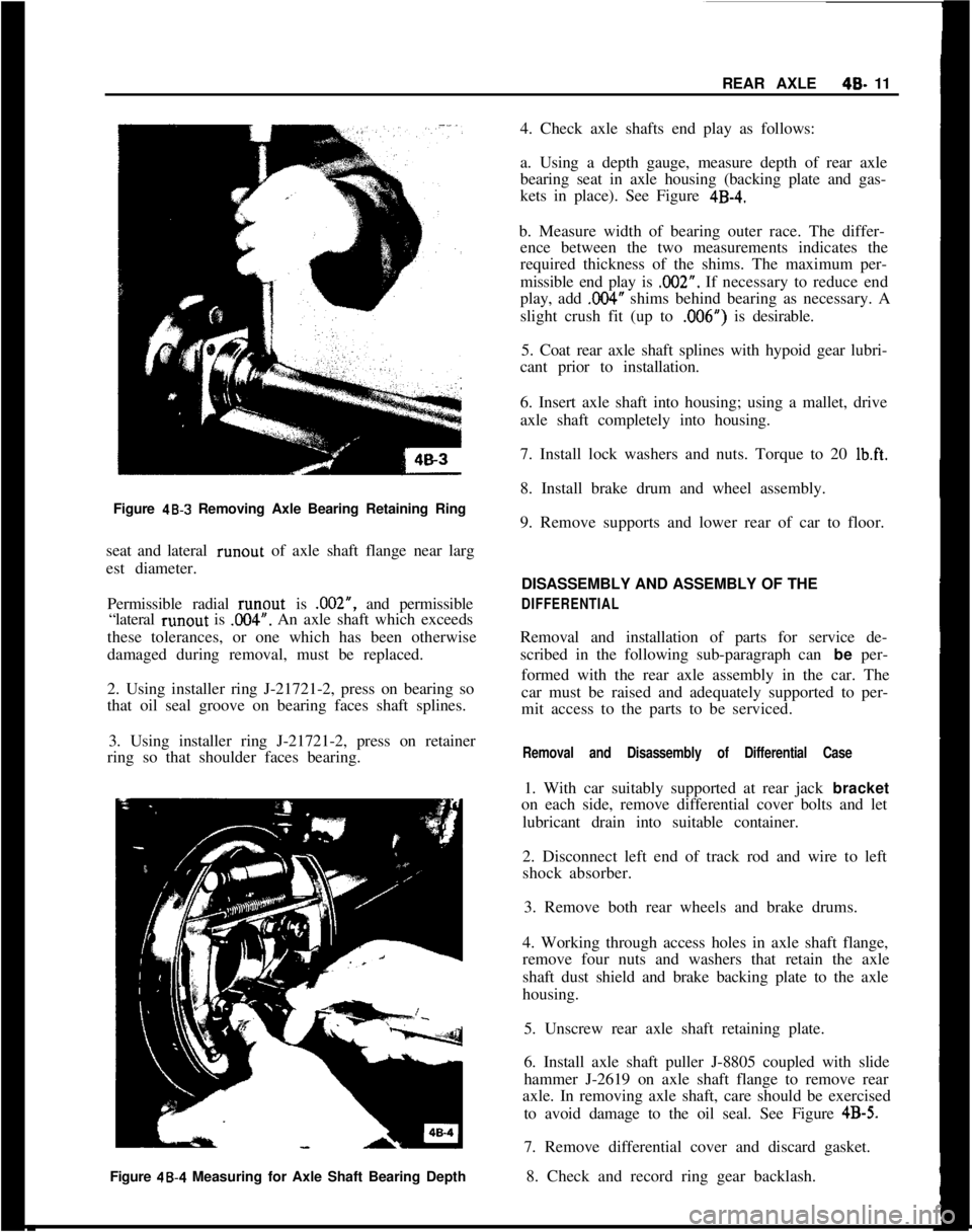
Figure
48-3 Removing Axle Bearing Retaining Ring
seat and lateral runout of axle shaft flange near larg
est diameter.
Permissible radial runout is .002”, and permissible
“lateral runout is
.OO4”. An axle shaft which exceeds
these tolerances, or one which has been otherwise
damaged during removal, must be replaced.
2. Using installer ring J-21721-2, press on bearing so
that oil seal groove on bearing faces shaft splines.
3. Using installer ring J-21721-2, press on retainer
ring so that shoulder faces bearing.
Figure 48.4 Measuring for Axle Shaft Bearing Depth4. Check axle shafts end play as follows:
a. Using a depth gauge, measure depth of rear axle
bearing seat in axle housing (backing plate and gas-
kets in place). See Figure
4B-4.b. Measure width of bearing outer race. The differ-
ence between the two measurements indicates the
required thickness of the shims. The maximum per-
missible end play is .002”. If necessary to reduce end
play, add
,004” shims behind bearing as necessary. A
slight crush fit (up to ,006”) is desirable.
5. Coat rear axle shaft splines with hypoid gear lubri-
cant prior to installation.
6. Insert axle shaft into housing; using a mallet, drive
axle shaft completely into housing.
7. Install lock washers and nuts. Torque to 20
Ib.ft.8. Install brake drum and wheel assembly.
9. Remove supports and lower rear of car to floor.
DISASSEMBLY AND ASSEMBLY OF THE
DIFFERENTIALRemoval and installation of parts for service de-
scribed in the following sub-paragraph can be per-
formed with the rear axle assembly in the car. The
car must be raised and adequately supported to per-
mit access to the parts to be serviced.
Removal and Disassembly of Differential Case1. With car suitably supported at rear jack bracket
on each side, remove differential cover bolts and let
lubricant drain into suitable container.
2. Disconnect left end of track rod and wire to left
shock absorber.
3. Remove both rear wheels and brake drums.
4. Working through access holes in axle shaft flange,
remove four nuts and washers that retain the axle
shaft dust shield and brake backing plate to the axle
housing.
5. Unscrew rear axle shaft retaining plate.
6. Install axle shaft puller J-8805 coupled with slide
hammer J-2619 on axle shaft flange to remove rear
axle. In removing axle shaft, care should be exercised
to avoid damage to the oil seal. See Figure
4B-5.7. Remove differential cover and discard gasket.
8. Check and record ring gear backlash.
Page 306 of 625
ENGINE MECHANICAL AND MOUNTS6A- 15New inlet valves must not be refaced or lapped with
grinding compound.The correct angle for the intake
and exhaust valve head is 44 degrees.10. Install cylinder head.
11. Adjust valve clearance. See MAINTENANCE
AND ADJUSTMENTS.
7. Inspect valve guides. Worn or pitted guides can be
reamed to accept valves with oversize stems. Over-
size valves are occasionally used in production.
Oversize valves are marked
’ 1 u “2” or “A” and are
stamped into the valve stem end and also stamped
near spark plug hole. See Figure 6A-22.
Replacing Rocker Arm Studs1. When replacing rocker arm studs become
neces-
sary, remove air cleaner, rocker arm cover and
rocker arm.
8. Reseat valve seats in cylinder head in the following
sequence:
Intake
NOTE:The rocker arm studs are screwed into the
cylinder head. A tapered part of the stem serves to
a void stud loosening.With 45 degrees cutter, remove burnt structure until
a metallic bright seat is obtained. Lightly coat valve
head with red lead, insert it into guide and turn it
under light pressure several times back and forth.
Thereby a contact pattern is obtained and the seat
width can be measured. If valve does not seat per-
fectly all around, lightly recut valve seat to the estab-
lished seat width of
,049” - .059” with 30 degrees
correction cutter.
ExhaustThe directions for reconditioning intake valve seats
apply in principle also to exhaust valve seat recondi-
tioning with the exception that the valve seat width
should be
.063-,073 in. and different cutters are em-
ployed.
NOTE:
: OTse new valve seals whenever
valves are reconditioned.9. Lube valves with engine oil and reinstall valves,
valve springs, caps and cap retainers using J-8062.
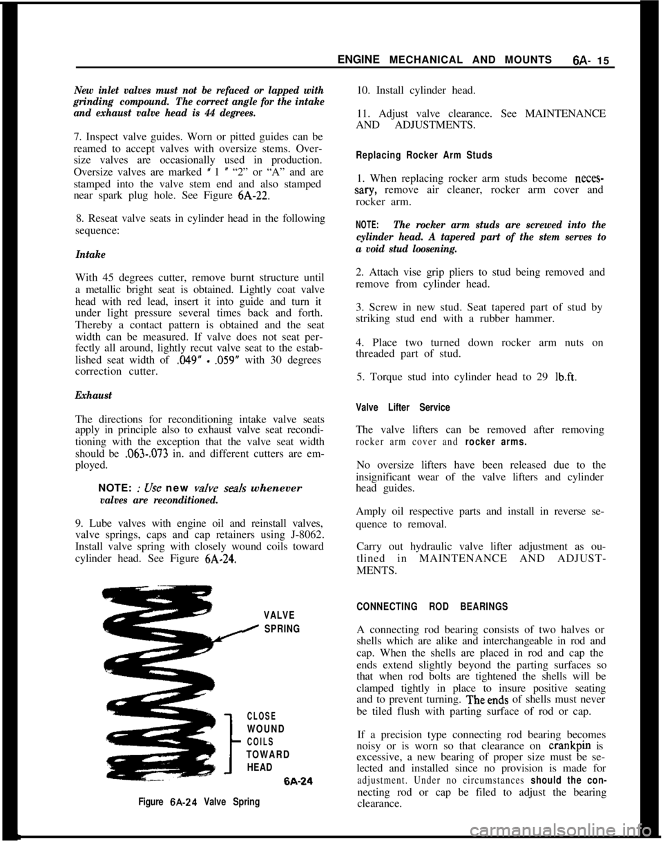
Install valve spring with closely wound coils toward
cylinder head. See Figure
6A-24.2. Attach vise grip pliers to stud being removed and
remove from cylinder head.
3. Screw in new stud. Seat tapered part of stud by
striking stud end with a rubber hammer.
4. Place two turned down rocker arm nuts on
threaded part of stud.
5. Torque stud into cylinder head to 29
lb.ft.
Valve Lifter ServiceThe valve lifters can be removed after removing
rocker arm cover and rocker arms.No oversize lifters have been released due to the
insignificant wear of the valve lifters and cylinder
head guides.
Amply oil respective parts and install in reverse se-
quence to removal.
Carry out hydraulic valve lifter adjustment as ou-
tlined in MAINTENANCE AND ADJUST-
MENTS.
VALVE
I SPRING
CLOSE
WOUND
COILS
TOWARD
HEAD6A-24
Figure 6A-24 Valve SpringCONNECTING ROD BEARINGSA connecting rod bearing consists of two halves or
shells which are alike and interchangeable in rod and
cap. When the shells are placed in rod and cap the
ends extend slightly beyond the parting surfaces so
that when rod bolts are tightened the shells will be
clamped tightly in place to insure positive seating
and to prevent turning. Theends of shells must never
be tiled flush with parting surface of rod or cap.
If a precision type connecting rod bearing becomes
noisy or is worn so that clearance on crankpin is
excessive, a new bearing of proper size must be se-
lected and installed since no provision is made for
adjustment. Under no circumstances should the con-necting rod or cap be filed to adjust the bearing
clearance.
Page 307 of 625
6A- 161973 OPEL SERVICE MANUALInspection of Connecting Rod Bearings and
Crankshaft JournalsRemove oil pan.
After removal of oil pan, disconnect two connecting
rods at a time from crankshaft and inspect the bear-
ings and crankpin journals. While,tuming crankshaft
it is necessary to
t&porarily reconnect the rods to
crankshaft to avoid possibility of damaging the jour-
nals through contact with loose rods.
If connecting rod bearings are chipped or scored they
should be replaced. If bearings
are in good physical
condition check for proper clearance on crankpins as
described under, checking clear$nce and selecting
replacement connecting rod beartngs.
If crankpin journals are scored or ridged, the crank-
shaft must be replaced, or reground for undersize
bearings, to insure satisfactory life of connecting rod
bearings. Slight roughness may be polished out withfine grit polishing cloth thoroughly wetted with en-
gine oil. Burrs may be honed off with a fine oil stone.
Use an outside micrometer to check crankpins for
out- of-round. If crankpins are mpre than
,002” out-
of- round, satisfactory life of new ,bearings cannot be
expected.
Checking Clearance and Selecting Replacement
Connecting Rod BearingsService bearings are furnished in standard size and
several undersizes. The clearance of connecting rod
(and crankshaft) bearings may be checked by use of
Plastigage, Type PG-1 (green), or equivalent, which
is soluble in oil.
1. Remove connecting rod cap with bearing shell.
Wipe off oil from bearing and crankpin journal, also
blow oil out of hole in crankshaft.
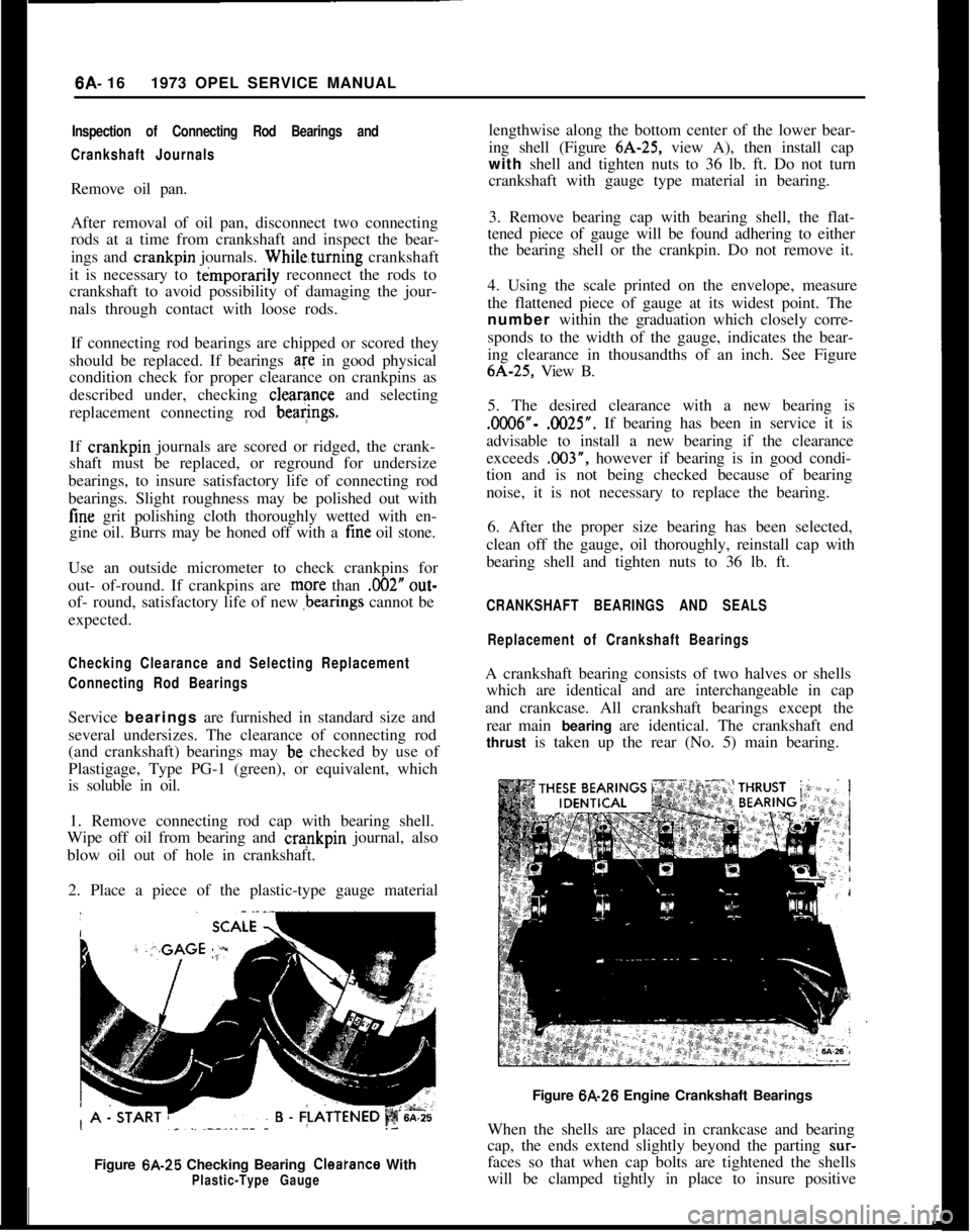
2. Place a piece of the plastic-type gauge material
Figure 6A-25 Checking Bearing
Cleatance WithPlastic-Type Gaugelengthwise along the bottom center of the lower bear-
ing shell (Figure 6A-25, view A), then install cap
with shell and tighten nuts to 36 lb. ft. Do not turn
crankshaft with gauge type material in bearing.
3. Remove bearing cap with bearing shell, the flat-
tened piece of gauge will be found adhering to either
the bearing shell or the crankpin. Do not remove it.
4. Using the scale printed on the envelope, measure
the flattened piece of gauge at its widest point. The
number within the graduation which closely corre-
sponds to the width of the gauge, indicates the bear-
ing clearance in thousandths of an inch. See Figure6A-25, View B.
5. The desired clearance with a new bearing is.0006”- .0025”. If bearing has been in service it is
advisable to install a new bearing if the clearance
exceeds .003”, however if bearing is in good condi-
tion and is not being checked because of bearing
noise, it is not necessary to replace the bearing.
6. After the proper size bearing has been selected,
clean off the gauge, oil thoroughly, reinstall cap with
bearing shell and tighten nuts to 36 lb. ft.
CRANKSHAFT BEARINGS AND SEALS
Replacement of Crankshaft BearingsA crankshaft bearing consists of two halves or shells
which are identical and are interchangeable in cap
and crankcase. All crankshaft bearings except the
rear main bearing are identical. The crankshaft end
thrust is taken up the rear (No. 5) main bearing.
Figure 6A-26 Engine Crankshaft Bearings
When the shells are placed in crankcase and bearing
cap, the ends extend slightly beyond the parting
sur-faces so that when cap bolts are tightened the shells
will be clamped tightly in place to insure positive
Page 313 of 625
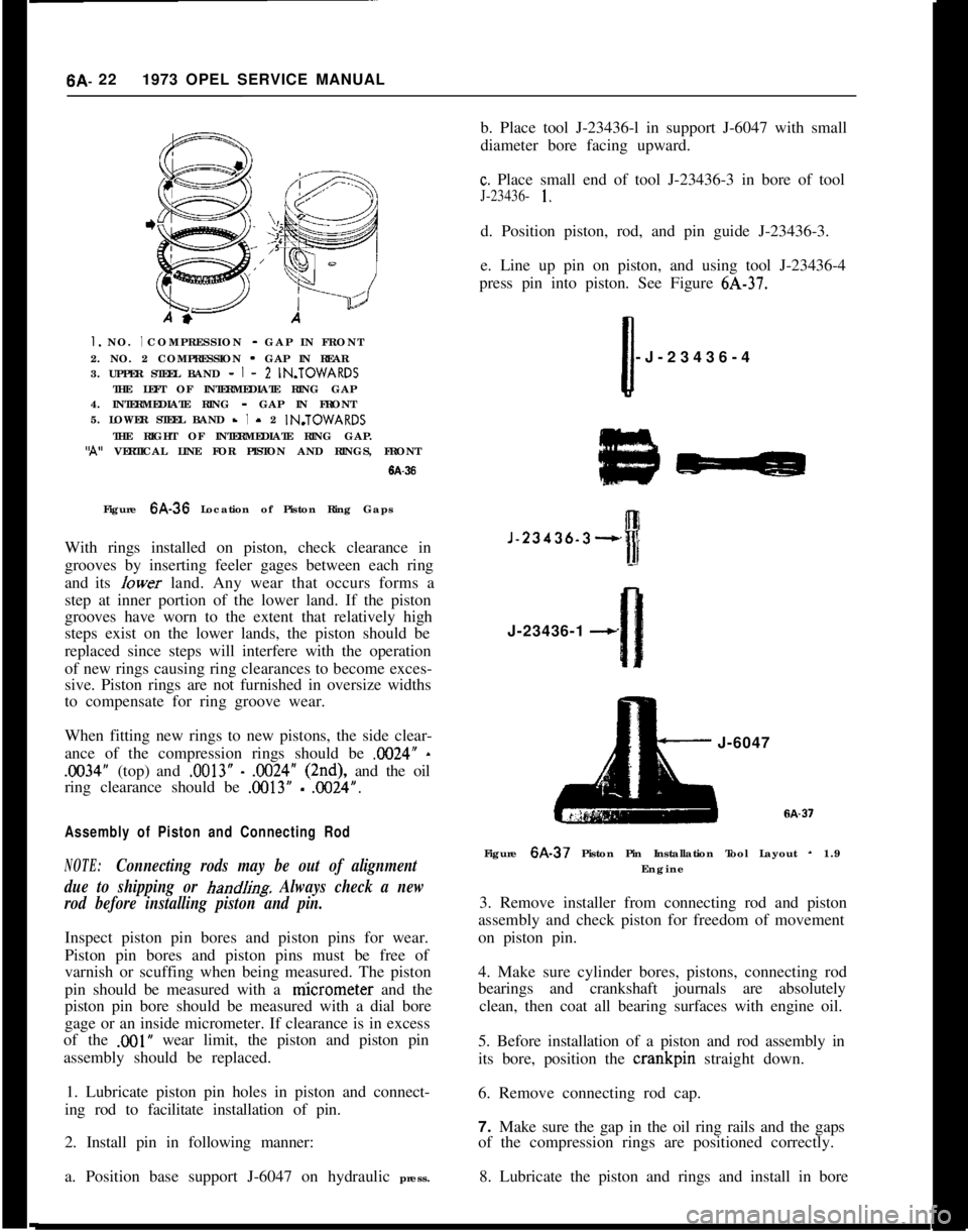
6A- 221973 OPEL SERVICE MANUALI. NO. I COMPRESSION - GAP IN FRONT
2. NO. 2 COMPRESSION - GAP IN REAR
3. UPPER STEEL BAND -
I - 2 IN.TOWARDS
THE LEFT OF INTERMEDIATE RING GAP
4. INTERMEDIATE RING - GAP IN FRONT
5. LOWER STEEL BAND -
I - 2 IN.TOWARDS
THE RIGHT OF INTERMEDIATE RING GAP.‘A” VERTICAL LINE FOR PISTON AND RINGS, FRONT
6A-36Figure 6A-36 Location of Piston Ring Gaps
With rings installed on piston, check clearance in
grooves by inserting feeler gages between each ring
and its Iower land. Any wear that occurs forms a
step at inner portion of the lower land. If the piston
grooves have worn to the extent that relatively high
steps exist on the lower lands, the piston should be
replaced since steps will interfere with the operation
of new rings causing ring clearances to become exces-
sive. Piston rings are not furnished in oversize widths
to compensate for ring groove wear.
When fitting new rings to new pistons, the side clear-
ance of the compression rings should be X024”
-
.1X34” (top) and .0013” - .OO24” (2nd), and the oil
ring clearance should be
.OO13” - .0024”.
Assembly of Piston and Connecting Rod
NOTE:Connecting rods may be out of alignment
due to shipping or
hand/i& Always check a new
rod before installing piston and pin.Inspect piston pin bores and piston pins for wear.
Piston pin bores and piston pins must be free of
varnish or scuffing when being measured. The piston
pin should be measured with a niicrometer and the
piston pin bore should be measured with a dial bore
gage or an inside micrometer. If clearance is in excess
of the
,001” wear limit, the piston and piston pin
assembly should be replaced.
1. Lubricate piston pin holes in piston and connect-
ing rod to facilitate installation of pin.
2. Install pin in following manner:
a. Position base support J-6047 on hydraulic press.b. Place tool J-23436-l in support J-6047 with small
diameter bore facing upward.
c. Place small end of tool J-23436-3 in bore of tool
J-23436- 1.d. Position piston, rod, and pin guide J-23436-3.
e. Line up pin on piston, and using tool J-23436-4
press pin into piston. See Figure 6A-37.
Ii-J-23436-4
J-23436-3--,J-23436-1
--cJ-6047
Figure 6A-37 Piston Pin Installation Tool Layout
- 1.9
Engine
3. Remove installer from connecting rod and piston
assembly and check piston for freedom of movement
on piston pin.
4. Make sure cylinder bores, pistons, connecting rod
bearings and crankshaft journals are absolutely
clean, then coat all bearing surfaces with engine oil.
5. Before installation of a piston and rod assembly in
its bore, position the crankpin straight down.
6. Remove connecting rod cap.
7. Make sure the gap in the oil ring rails and the gaps
of the compression rings are positioned correctly.
8. Lubricate the piston and rings and install in bore
Page 321 of 625
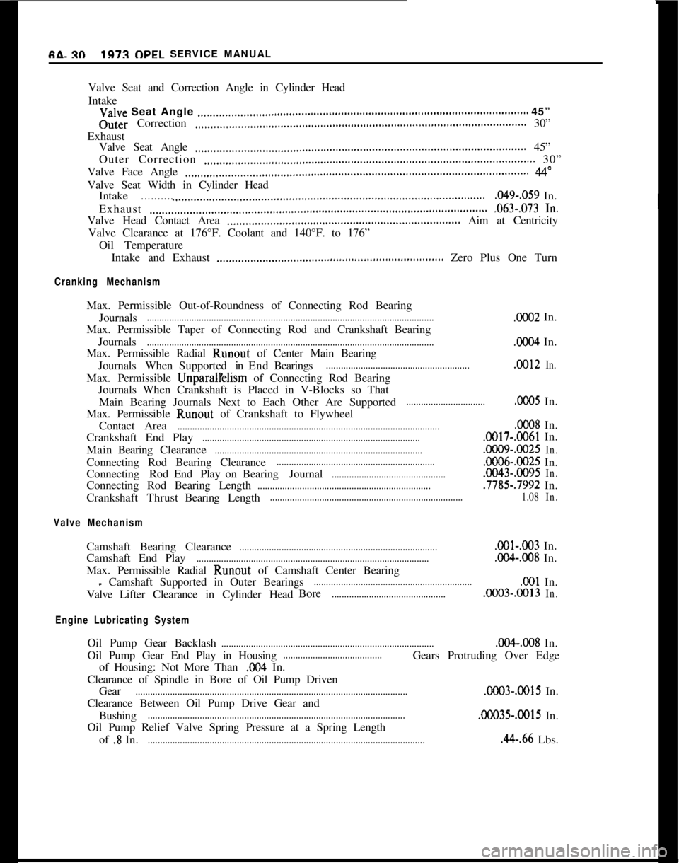
GA. xl1973 OPEL SERVICE MANUAL
Valve Seat and Correction Angle in Cylinder Head
Intake
Valve Seat Angle ..,._,..__....,,..,,,..,.,.,.,..............,............................................................... 45”Outer Correction
.,,,.,,._.,._..___,,,.,,,,,.......,,.,..,...,,..,..,,..,,..,,,.............................................. 30”
Exhaust
Valve Seat Angle
,,,.,,.__,.__..___.,..,,..,...,,....,..,..,..,,..,..,...,..,,,...,,......................................... 45”
Outer Correction
.,,..,,...,._.,.__....,,,.....,,,........................................................................... 30”
Valve Face Angle
,,..,,,..,.__..__.._..,,,..,,...,,......,.,..,..,..,,.,,,..,..,,,..,,,..,,,...,,................................ 44”Valve Seat Width in Cylinder Head
Intake
. . . . . . . . . . .._..._._.................,,..,.....,,..,............,...,..,,,..,,..,,...,,...,,,..,..................049-,059 In.
Exhaust
.,..,,,..,,.___..,,..,,...,..,,,..,,...,,...,,...............,,..,,..........,,....,,...,..................... .063-,073 In.Valve Head Contact Area
,,..,,,..,,___.__.,,..,,..,.,,..........,...,,..,,............,,,...,....... Aim at Centricity
Valve Clearance at 176°F. Coolant and 140°F. to 176”
Oil Temperature
Intake and Exhaust
_.,,..,,,,,,..,,....,...,,,.,.,,,.,..........................,,,..,,,,.... Zero Plus One Turn
Cranking MechanismMax. Permissible Out-of-Roundness of Connecting Rod Bearing
Journals
.....................................................................................................................OC02 In.
Max. Permissible Taper of Connecting Rod and Crankshaft Bearing
Journals
.....................................................................................................................ooO4 In.
Max. Permissible Radial Runout of Center Main Bearing
JournalsWhenSupportedinEndBearings
...........................................................0012In.Max. Permissible UnparalYelism of Connecting Rod Bearing
Journals When Crankshaft is Placed in V-Blocks so That
Main Bearing Journals Next to Each Other Are Supported
................................0005 In.
Max. Permissible Runout of Crankshaft to Flywheel
Contact Area
...........................................................................................................0008 In.
Crankshaft End Play
.........................................................................................GOl7-.CO61 In.
MainBearingClearance
.....................................................................................ooO9-.@I25In.Connecting Rod Bearing Clearance
.................................................................ooO6-.0025 In.
Connecting RodEnd PlayonBearing Journal
...............................................0043-.0095In.Connecting Rod Bearing Length
.......................................................................7785-.7992 In.
CrankshaftThrustBearingLength
..............................................................................1.08In.
Valve MechanismCamshaft Bearing Clearance
.................................................................................OOl-,003 In.
Camshaft End Play
...............................................................................................004-038 In.
Max. Permissible Radial Runout of Camshaft Center Bearing
- Camshaft Supported in Outer Bearings................................................................,001 In.
ValveLifter Clearance in Cylinder HeadBore
...............................................0003-.OOl3In.
Engine Lubricating SystemOil Pump Gear Backlash
......................................................................................0%.008 In.
Oil Pump Gear End Play in Housing
........................................Gears Protruding Over Edge
of Housing: Not More Than
,004 In.
Clearance of Spindle in Bore of Oil Pump Driven
Gear
...............................................................................................................OCO3-.0015 In.
Clearance Between Oil Pump Drive Gear and
Bushing
.........................................................................................................00035-.OOl5 In.
Oil Pump Relief Valve Spring Pressure at a Spring Length
of
.8 In..................................................................................................................44-.66 Lbs.