Pump OPEL MANTA 1973 Owner's Guide
[x] Cancel search | Manufacturer: OPEL, Model Year: 1973, Model line: MANTA, Model: OPEL MANTA 1973Pages: 625, PDF Size: 17.22 MB
Page 347 of 625
6E- 561973 OPEL SERVICE MANUAL
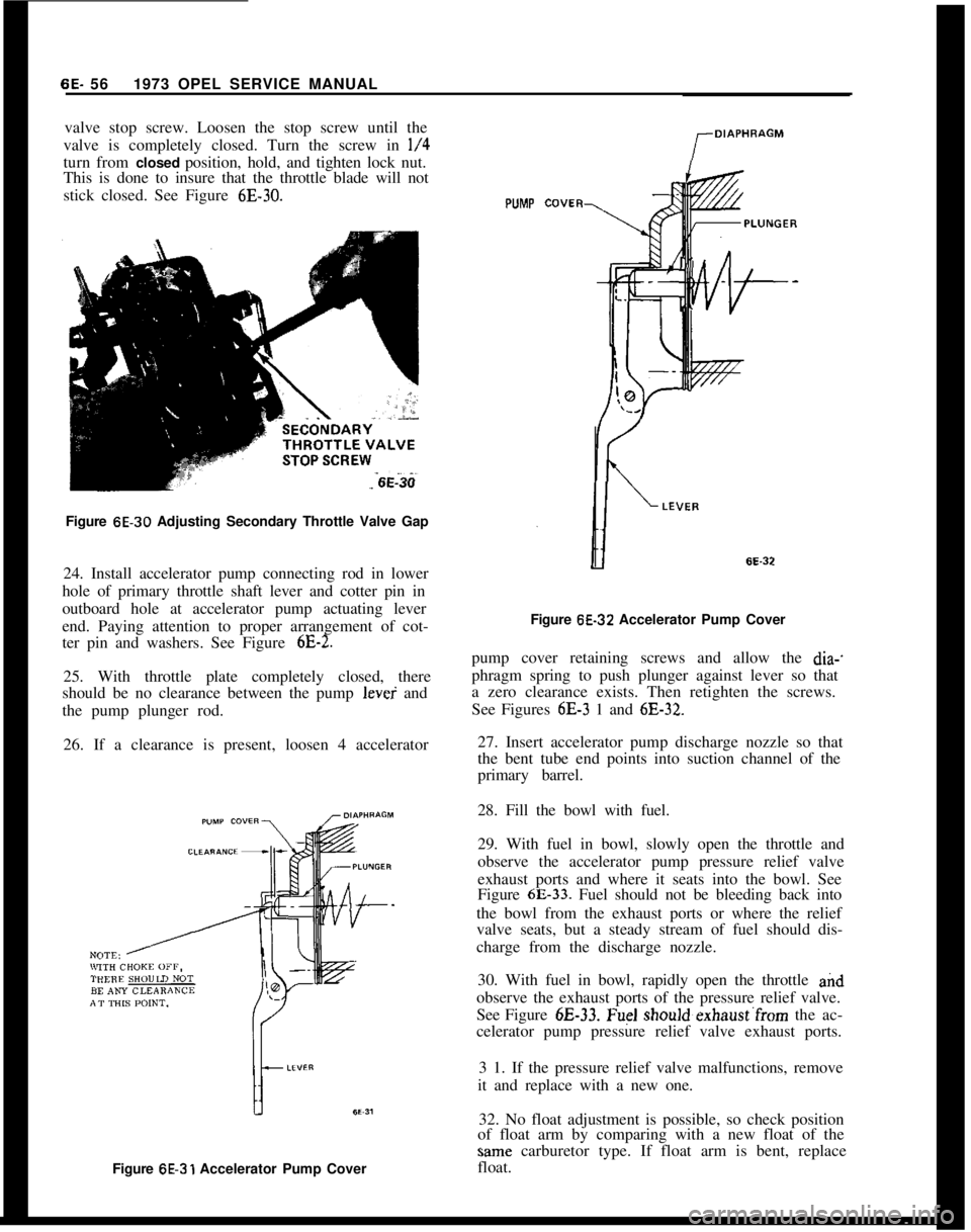
valve stop screw. Loosen the stop screw until the
valve is completely closed. Turn the screw in l/4turn from closed position, hold, and tighten lock nut.
This is done to insure that the throttle blade will not
stick closed. See Figure
6E-30.PUMPFigure 6E-30 Adjusting Secondary Throttle Valve Gap
24. Install accelerator pump connecting rod in lower
hole of primary throttle shaft lever and cotter pin in
outboard hole at accelerator pump actuating lever
end. Paying attention to proper arrangement of cot-
ter pin and washers. See Figure
6E-2.25. With throttle plate completely closed, there
should be no clearance between the pump levei and
the pump plunger rod.
26. If a clearance is present, loosen 4 accelerator
Figure
6E-31 Accelerator Pump CoverFigure 6C32 Accelerator Pump Cover
pump cover retaining screws and allow the
dia-’phragm spring to push plunger against lever so that
a zero clearance exists. Then retighten the screws.
See Figures
6E-3 1 and 6E-32.27. Insert accelerator pump discharge nozzle so that
the bent tube end points into suction channel of the
primary barrel.
28. Fill the bowl with fuel.
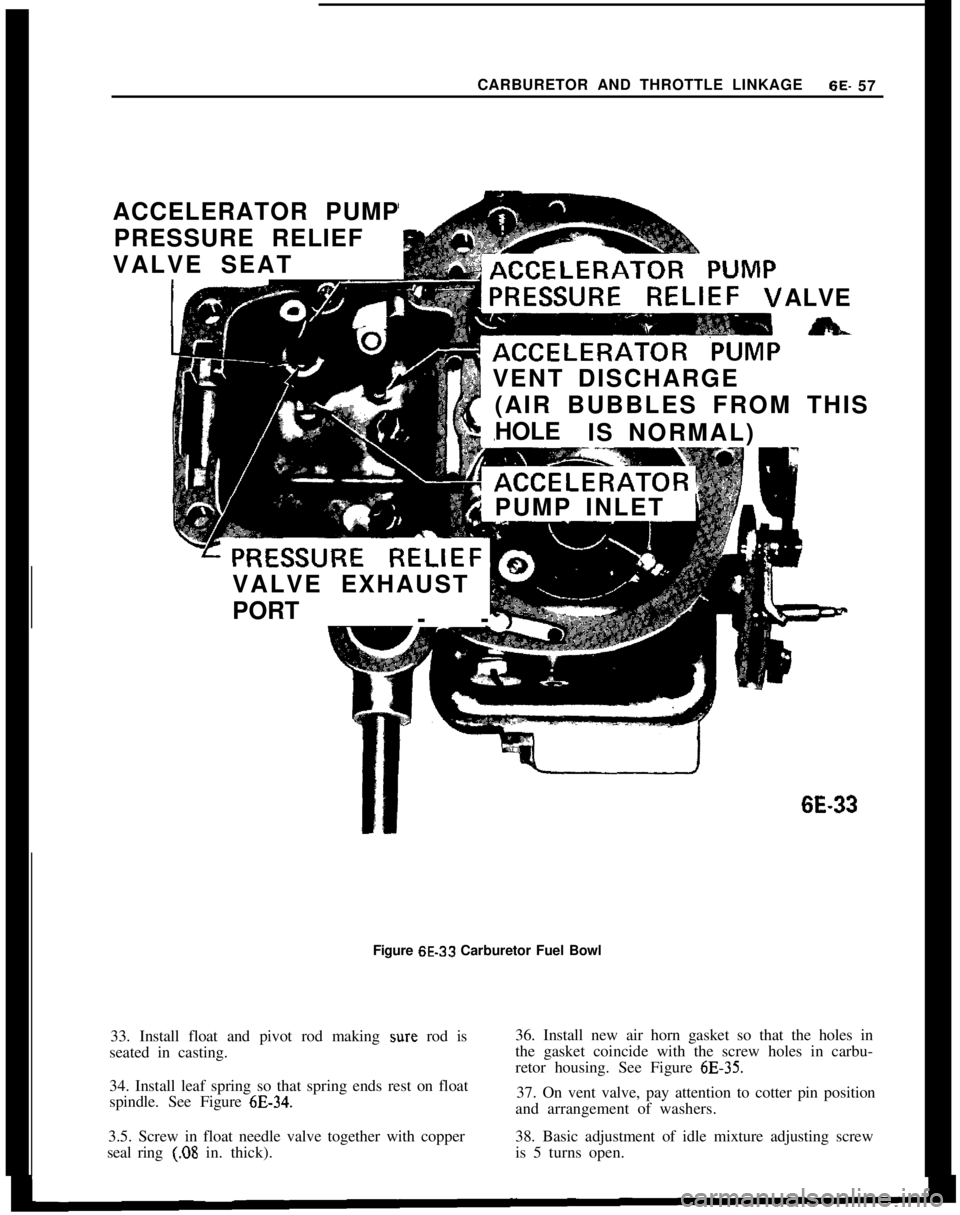
29. With fuel in bowl, slowly open the throttle and
observe the accelerator pump pressure relief valve
exhaust ports and where it seats into the bowl. See
Figure
6E-33. Fuel should not be bleeding back into
the bowl from the exhaust ports or where the relief
valve seats, but a steady stream of fuel should dis-
charge from the discharge nozzle.
30. With fuel in bowl, rapidly open the throttle atid
observe the exhaust ports of the pressure relief valve.
See Figure
6E-33. Fuel should~exhaust’from the ac-
celerator pump pressure relief valve exhaust ports.
3 1. If the pressure relief valve malfunctions, remove
it and replace with a new one.
32. No float adjustment is possible, so check position
of float arm by comparing with a new float of thesame carburetor type. If float arm is bent, replace
float.
Page 348 of 625
CARBURETOR AND THROTTLE LINKAGE6E- 57
ACCELERATOR PUMP
PRESSURE RELIEF
VALVE SEAT
ALVE
VENT DISCHARGE
(AIR BUBBLES FROM THIS
HOLE
IS NORMAL)
PUMP INLET
VALVE EXHAUST
PORT
--6E-33
Figure 6E-33 Carburetor Fuel Bowl
33. Install float and pivot rod making sure rod is
seated in casting.36. Install new air horn gasket so that the holes in
the gasket coincide with the screw holes in carbu-
retor housing. See Figure
6E-35.34. Install leaf spring so that spring ends rest on float
spindle. See Figure
6E-34.37. On vent valve, pay attention to cotter pin position
and arrangement of washers.
3.5. Screw in float needle valve together with copper38. Basic adjustment of idle mixture adjusting screw
seal ring
(.08 in. thick).is 5 turns open.
Page 349 of 625

6E- 581973 OPEL SERVICE MANUAL
Figure 6E-34 Leaf Spring Installed
1 6E-36
Figure 6E-36 Checking Vent Valve Adjustment
39. Check compression of vent valve lower spring. It
should be compressed
l/4 inch with throttle valve
completely closed. See Figure
6E-36.40. Correct by bending valve lever.
Figure
6E-35 Installing Cover Gasket
SPECIFICATIONS
GENERAL SPECIFICATIONSCompression Ratio
........................................................................................................7.6 to 1
Fuel Required
................................(...........................................................................Low Lead
Fuel Tank Capacity (Gallons)
Opel1900andManta..
....................................................................................................11.9
GT...................................................................................................................................13.2Fuel Gauge Type
........................................................................................................Electrical
FuelPumpType
......................................................................................................Mechanical
FuelPumpDrive
..................................................................................EccentriconCamshaft
Fuel Pump Pressure at 1950 RPM
......................................................................3.1 to 3.7 psi
FuelFilter
............................................................................................................In-LineFilter
CarburetorMakeandType................................................I-Solex2BBLAutomaticChoke
AirCleanerElementType
..........................................................................FiberMesh-Paper
Page 358 of 625
2. If inspection of contact points indicates excessive
burning, pitting or wear, check condenser and re-
place if necessary.
3. Inspect all connections and wires in the primary
ignition circuit. Correct any abnormal conditions
found.Carburetor1. Clean fuel strainer in fuel pump. To prevent fuel
leakage in pump, disconnect “IN” line from pump
and raise end above fuel level. The in-line fuel filter
should be replaced every 12,000 miles or every 12
months.
2. Check for freedom of choke valve operation and
clean shaft if necessary, with suitable solvent.
3. Inspect throttle cable or linkage bracket and re-
turn spring for wear. With helper depressing acceler-
ator pedal to floor, check for wide open throttle.
Adjust accelerator pedal height so wide open throttle
is obtained when pedal is within
l/2 inch from floor.
Lubricate linkage pivot points with engine oil.
Air CleanerCheck paper element every 6,000 miles and replace
every
24,ooO miles. If a vehicle is operated in dusty
territory, check condition of air cleaner element
more frequently and replace if necessary.
Fan Belt1. Inspect belt for wear, cracks or frayed points.
Replace and/or adjust as necessary. Specified ten-
sion for belt using Gauge J-23600 is 45 lbs.
Cooling System1. Inspect the radiator, water pump, cylinder head
areas and all radiator and heater hose connections
for evidence of engine coolant leaks.
2. Inspect all hoses for deterioration from gas and oil
contact. Correct as required.
Inspection should be made with engine operating at
normal temperature, cooling system completely
filled, temperature control lever fully open and nor-
mal pressure in the system. Normal pressure should
be 13.2 to 15.2 psi.
Engine Lubrication SystemInspect engine for evidence of oil leakage. Correctany abnormal condition with sealastic or new seals
and gaskets.
Battery
1. Inspect battery, battery mount and cables and
check electrolyte level. Proper level should be just
above the cell plates.
CAUTION:Do not over fill.
2. Determine the serviceability of the battery by ap-
plying the 421 Battery Test.
Positive Crankcase VentilationClean crankcase ventilator metered orifice in the in-
take manifold fitting every 6,000 miles. Also all hoses
and fittings should be inspected, cleaned and re-
placed, if necessary.
To clean, remove rubber hose from metered orifice
and apply air pressure to orifice to remove any for-
eign particles that may be trapped.
Valve Lifter AdjustmentRefer to Engine Mechanical and Mounts section for
valve lifter adjustment procedure.
Engine Tune-Up Instrument ChecksThe following instrument checks and adjustments
serve as a final check on engine condition. These
checks may discover some new problems that may
not have been obvious before. The engine is also
given its final adjustments that will assure maximum
performance, reliability, and proper emission con-
trol.
Refer to Electrical Group for checking procedures of
the following:
Cranking Voltage Check
Ignition Timing
Distributor Advance
Ignition Output
Secondary Resistance
Current Output and Voltage Setting
Idle Speed and Mixture AdjustmentsRefer to carburetor section.
Page 397 of 625

7C- 361973 OPEL SERVICE MANUAL
CONTENTS
Subject
DESCRIPTION AND OPERATION:
Description of the Opel Three-Speed Automatic,Transmission....................................................................
Principles of Operation....................................................
ComponentOperation
andLocation............................
Mechanical Operation......................................................
Hydraulic Control Units and Valves............................H,y&aulic Operation..........................................................
DIAGNOSIS:
Sequence for Trouble Diagnosis..................................
Checking
Procedures........................................................
ExternalOil
Leaks..............................................................
Trouble
DiagnosisChart..................................................
Hydraulic Pressure
Checks............................................
MAINTENANCE AND ADJUSTMENTS:
Detent Cable Adjustment..............................................
ServicingSelector
Lever..................................................
MAJOR REPAIR:
Transmission Removal and Installation
AllModels........................................................................
Removalof
OilPan............................................................
RemovalofValveBody....................................................
Removalof
ServoPiston................................................
Removalof
Selector
LeverandShaft........................
RemovalofModulatorAssembly..................................
RemovalofDetentValveAssembly............................
RemovalofExtensionHousing......................................
Removal of Speedometer Drive Gear, Governor
Body and Governor Hub..............................................
Removal of Converter Housing, Oil Pump, Reverse
and Second Clutch Assembly..................................
Removal of Third Clutch Assembly, Planetary
Carrier Assembly, Reaction Sun Gear and Drum
Assembly and Low Bank............................................
Disassembly, Inspection and Reassembly of
Converter Housing, Oil Pump and Reverse Clutch
Disassembly, Inspection and Reassembly of
SecondClutch
................................................................
Disassembly, Inspection and Reassembly of
ThirdClutch....................................................................
Disassembly, Inspection and Reassembly of
Planetary Carrier
............................................................Page No.7c- 377c- 387c- 447c- 487c- 487c- 64
7C- 81
7C- 81IC- 817c- 827c- 877c- 917c- 937c- 947c- 99.7c- 99
7c-1007c-loo
7&l 01
7c-102
7c-102
7c-103
7c-103
7c-104
7c-105
7c-111
7c-114
7c-118
Page 398 of 625

AUTOMATIC TRANSMISSION7c- 37
Disassembly, Inspection and Reassembly of
ReactionSunGearandDrum....................................
Disassembly, Inspection and Reassembly of
Governor Body................................................................
Disassembly, Inspection and Reassembly of
GovernorHub..................................................................
Disassembly, Inspection and Reassembly of
ExtensionHousing........................................................
Disassembly, Inspection and Reassembly of
Servo Piston....................................................................
Disassembly, Inspection and Reassembly of
ValveBody........................................................................
Disassembly, Inspection and Reassembly of
Case....................................................................................
InspectingandTestingConverter................................
InstallationofSelectorLeverandShaft....................
InstallationofLowBand................................................
Installation of Reaction Sun Gear and Drum..........
Installation of Output Shaft and Planetary
Carrier................................................................................
Installation of Second and Third Clutch Assemblies
IntoCase..........................................................................
InstallationofReverseClutch......................................
DeterminingSelectiveWasherSize............................
Installation of Converter Housing, Oil Pump and
Clutch Assembly............................................................
Installation of Governor Assembly..............................
InstallationofExtensionHousing................................
InstallationofSpeedometerDrivenGear..................
Installation of Detent Valve, Modulator Valve
and Modulator Assembly............................................
Installation and Adjustment of Servo........................
InstallationofValveBody..............................................
InstallationofOilPanandGasket..............................
Torque Converter..............................................................
SPECIFICATIONS:
GeneralSpecifications......................................................
7c.
7c-
,l
‘118
197c-1207c-1207c-1207C-121
7C-124
7C-125
7C-125
7C-125
7C-127
7C-127
7C-127
7C-128
7C-129
7C-129
7C-129
7c-130
7c-131
7c-131
7c-131
7C-132
7c-133
7c-134
7c-134DESCRIPTION AND OPERATION
DESCRIPTIONThe Opel Three-Speed Automatic is a fully auto-matic unit utilizing a torque converter and a Ravig-neaux planetary gear set, with three multiple disc
clutches and a single band to provide three forward
speeds and reverse. See Figure 7C-71. Automatic
upshifts and downshifts are controlled by road speed,
engine vacuum and an accelerator pedal connection
to the transmission.
Page 399 of 625

Figure 7C-1 Quadrant In Park Position -Opel 1900
and Manta7C- 381973 OPEL SERVICE MANUAL
R
- Reverse enables the vehicle to be operated in a
reverse direction.
N
- Neutral position enables the engine to be
started and operated without driving the vehicle.
D
- Drive range is used for all normal driving
conditions and maximum economy and has three
gear ratios. Downshifts are available for passing
by depressing the accelerator partially at lower
car speeds and through the “detent” at higher car
speeds.
S or 2
- Second range adds new performance for
hilly terrain. It has the same starting ratio as Drive
range, but prevents the transmission from shifting
above second gear to retain second gear for
acceleration or engine braking as desired. Second
range can be selected at any vehicle speed, but
should not be used above the speed shown m the
Owner’s Manual. This is to prevent over-speeding
the engine. The transmission will shift to second
gear immediately and remain in second until the
vehicle speed or the throttle position is changed
to obtajn first gear operation in the same manner
as in Drive range.
L or 1
- Lo range can be selected at any vehicle speed,
but should not be used above the speed shown in the
Owner’s Manual. The transmission will shift to low
(1st) gear immediately and remain in 1st gear regard-
less of vehicle speed or throttle position. This is par-
ticularly beneficial for maintaining maximum engine
braking.
PRINCIPLES OF OPERATION
Torque ConverterThe torque converter acts as a coupling to transmit
engine torque, through oil, to the transmission power
train. It also multiplies the torque from the engine
under certain conditions of input and output speed.
Figure
7C-2 Quadrant in Park Position - GT Models
The quadrant has six positions indicated in the fol-
lowing order: (Opel 1900 and Manta) P,R,N,D,S,
and L (Figure
7C-1); and (GT) P,R,N,D,2, and 1
(Figure 7C- 2).The torque converter used in the Opel three speed
automatic transmission consists of three basic ele-
ments: the pump (driving member), the turbine
(driven or output member) and the stator (reaction
member). See Figure
7C-3. The converter cover is
welded to the pump to seal all three members in an
oil tilled housing.
P
- Park position enables the transmission output
shaft to be locked
- thus preventing the vehicle
from roling either forward or backward. Because
the output shaft is mechanically locked by a
parking
paw1 anchored in the extension housing,
the park position should not be selected until the
vehicle has come to a stop. The engine may be
started in the Park position.Whenever the engine is running, the converter pump
turns at engine speed and acts as a centrifugal pump,
picking up oil at its center, adding energy, and dis-
charging the oil at its outer rim between the blades.
The shape of the converter pump shells and blades
cause the oil to leave the pump spinning in a clock-
wise direction toward the blades of the turbine. Asthere is no mechanical connection between converterpump and turbine, the oil is the only driving force
and strikes the blades of the turbine, transferring the
Page 400 of 625

AUTOMATIC TRANSMISSION7c- 39
TURBINESTATOR
(DRIVEN MEMBER)fREACTION
MEMBER)CON;ERTER
COVERP;MP
(DRIVING MEMBER)
7c.3Figure
7C-3 Torque Converter Assembly
energy of the oil to the turbine. See Figure
7C-1. The
driven member, or turbine is splined to the transmis-
sion input shaft to transmit turbine torque to the
transmission gear train.
When the engine is idling, the converter pump is
being driven slowly. The energy of the oil leaving the
pump is very low, therefore there is very little torque
imparted to the turbine. For this reason, the engine
can idle and the car will have little or no tendancy
to “Creep.”
As the throttle is opened and pump speed increases,
the force of the oil leaving the pump increases and
the resultant torque is absorbed by the turbine.
After the oil has imparted its force to the turbine
member, oil leaving the turbine follows the contour
of the turbine blades so that it leaves the turbine
spinning counterclockwise. Since the turbine mem-
ber has absorbed the energy required to reverse the
direction of the oil, the turbine now has greater forceor torque than is being delivered by the engine, and
the process of torque multiplication has begun.TURBINE
PUMPTURBINE
PUMP7c4Figure
7C-4 Oil Flow Without Stator
If the counterclockwise spinning oil were allowed to
return directly to the converter pump, the oil would
strike the inner section of the pump blades in a direc-
tion that would hinder its rotation, cancelling out
any gains in torque that have been obtained. To pre-
vent this, a stator assembly is added, and is located
between the converter pump and turbine. See Figure7c-5.
The stator redirects the oil returning to the pump
member of the converter and changes its direction of
rotation to that of the pump. Since the direction of
the oil leaving the stator is not opposing the rotationof the pump, the energy or torque of the engine is
added to the oil as it passes through the
the entire cycle repeats. See Figure
7C-6.pump and
The force of the returning oil from the turbine tends
to rotate the stator in a counterclockwise direction,
the stator is mounted on a one-way or roller clutch
which allows it to turn clockwise but not counter-
clockwise. Therefore, at low turbine speeds, the re-
turning oil from the turbine striking the stator blades
in a counterclockwise direction causes the roller
clutch to “lockup,” and prevent the stator from turn-
ing.
As the turbine speed increases, the direction of the
oil leaving the turbine changes and flows against thestator blades in a clockwise direction. Since the sta-tar would now be hindering the smooth flow of re-
turning oil to the pump, the roller clutch releases,
and the stator rotates freely on its shaft. With this
condition, the stator becomes ineffective and no fur-
ther multiplication of engine torque is produced
within the converter. At this point the converter acts
Page 401 of 625

7C- 401973 OPEL SERVICE MANUAL
ENERGIZING SPRINGS
UTER RACE (CAM)
ROLLER CLUTCHSTATOR
LOCKS UPSTATOR
COUNTER CLOCKWISE FORCES ON CAM, LOCKOVERRUNS
ROLLERS TO INNER RACE
CLOCKWISE FORCES ON CAM CAUSESTATOR ASSEMBLYx.5
ROLLERS TO OVERRUN INNER RACE
Figure 7C-5 Roller Clutch And Stator Assembly
as a fluid coupling, since both the converter pump
and turbine are turning at the same speed, or at a 1:l
ratio.
The torque converter and input shaft actually form
a simple transmission in themselves, however, since
the requirements of an automobile transmission are
greater, some means of providing additional torque,
neutral and reverse, are required. For this reason a
gear set is added behind the torque converter.
Planetary Gears
Planetary gears are used in automatic transmissions
as the basic means of multiplying the twisting force
or torque from the engine. They are so named be-
cause of their physical arrangement and are used
because they permit constant mesh operation, cannot
clash, operate in a minimum of space and distribute
the load over several gears. The simplest planetary
gear set consists of a center or sun gear, internal or
ring gear and a planetary gears called planetary pin-
ions. See Figure
7C-9. The sun gear meshes with theplanetary pinions which rotate freely on their shafts
attached to the planetary carrier. The ring gear
sur-rounds the assembly and meshes with the planetary
pinions. Power flow through the planetary gear set
is accomplished by applying power to one member,
holding another member thus making it a reaction
member and obtaining the transmitted power from
the third member, which can result in any of the
following conditions:
1. Increase torque with a proportional decrease in
output speed.
2. Increase speed with a proportional decrease of
output torque.
3. Reverse direction of rotation.
4. Act as a direct connection for direct drive.
The gear set used in the Opel Three Speed Automatic
transmission is known as a Ravigneaux planetary
Page 405 of 625

causes the sprags to wedge and prevent rotation in
one direction, and to allow free rotation in the oppo-
site direction.7C. 441973 OPEL SERVICE MANUAL
The clutch is released by exhausting the oil from
behind the piston. The release springs push the pis-
ton to the released position, thereby removing the
force from the plates. See Figure 7C-16.Band
A band is used to hold one planetary member sta-
tionary with relation to the other planetary mem-
bers.
!See Figure 7C-19. The band is connected to the
SPR
7C-16Figure
7C-16 Sprag Cage Assembly
Sprag C(utchA sprag clutch is an overrunning clutch which allows
rotation in one direction only and consists of an inner
race, an outer race and the sprag assembly.
The sprag assembly itself consists of sprags, retainer
rings and a spring. See Figure 7C- 16. The sprags are
mounted at intervals between the two concentric re-
taining rings. The spring is located between the rings
and surrounds the ‘narrow portion of the sprags.
One diagonal dimension of each sprag is greater than
the distance between the inner and outer race, while
the other diagonal is less. See Figure
7C-17. This
\ \I’b+ SPRAG
DISTANCE AFigure
7C-17 Sprag Operational Schematictransmissio; case (stationary anchor) and is ope-
rated by a servo piston. One band is used in the Opel
Three: Speed Automatic Transmission and holds the
reaction sun gear and drum stationary in first and
second gear.
BAND\- D7uM
PRESSURE
STATIONARY
PASSAGE
yPlSfON
1 y””SERVO BODY RELEASE SPRING
7c19
Figure
7C-19 Band Application
COMPONENT OPERATION AND LOCATIONThe power flow and principles of operation of the
Opel Three Speed Automatic Transmission power
train are most easily understood when each unit is
considered separately with a part by part build up of
the unit.
The torque converter is connected to the engine by
means of a flex plate which is bolted directly to the
engine crankshaft and to the converter cover. The
converter cover is welded to the converter pump
member which provides a direct connection of the
engine to the converter. The converter pump hub tits
into the transmission oil pump driving the oil pump
whenever the engine is operating. See Figure
7C-20.The input shaft is splined into the hub of the turbine,
delivering the converter’s output torque to the trans-
mission gear train. See Figure
7C-21.