Pump OPEL MANTA 1973 Repair Manual
[x] Cancel search | Manufacturer: OPEL, Model Year: 1973, Model line: MANTA, Model: OPEL MANTA 1973Pages: 625, PDF Size: 17.22 MB
Page 471 of 625

7C-1101973 OPEL SERVICE MANUALHSEAL
REVERSE CLUTCH
Figure
7C-151Figure 7C-153Figure
7C-15230. Install new oil seals on reverse clutch piston. See
Figure
7C-153.31. Install reverse clutch piston onto rear face of oil
pump using liberal amount of transmission fluid. See
Figure
7C-154.32. Inspect reverse clutch piston springs. Evidence of
extreme heat or burning in the area of the clutch may
have caused the springs to take a heat set and would
justify replacement of the springs.
33. Install the twenty-four reverse clutch piston re-
turn springs.Figure
7C-15434. Install retaining seat.
35. Compress return springs using second and re-
verse clutch piston spring compressor tool J-2590-12
with adapter J-21420-1. Care should be taken not to
damage retainer should retainer catch in snap ring
groove. See Figure 7C-155.
36. Install snap ring using snap ring pliers such as
J-8059. See Figure 7C-155. Do not air check reverse
clutch as the clutch is not complete and damage to
the return spring retaining seat may occur.
Page 472 of 625

AUTOMATIC TRANSMISSION 7C-111
OIL PUMP /’ASSEMBLY
ASPklNG
I(ETAINERSNAP RING
PLIERS
h7C146
Figure 7C.15537. Turn oil pump and reverse clutch assembly so
that oil pump face is facing up.
38. Install oil pump gears using the location mark
made before disassembly.
39. Check the end clearance of both gears to the oil
pump face. Clearance should be between
.0005 to
.0035. See Figure 7C-156.Disassembly, Inspection and Reassembly of Second
Clutch
1. Remove ring gear retaining ring from second
clutch drum. See Figure X-157.
GEAR
Figure
7C-1572. Remove ring gear. See Figure
7C-158.
SECOND CLUTCH DRUM
:-157Figure
7C-15641. Replace the oil pump assembly if the end clear-
ance is not within specifications.Figure 76.158
3. Remove second clutch spacer plate retaining ring.
4. Remove second clutch spacer plate. See Figure7c- 159.
Page 485 of 625
7C.1241973 OPEL SERVICE MANUAL
14. Remove the downshift timing valve plug retain-
ing pin and remove downshift timing valve plug.
Remove the low speed downshift timing valve and
spring.
15. Remove the manual low and r&erse control
valve retaining pin. Remove the spring and the
manual low control valve and the reverse control
valve.
16. Remove the l-2 accumulator valve retaining pin
and remove the l-2 accumulator valve plug, l-2 ac-
cumulator valve and spring.
17. A clean work area which is free of dirt and dust
should be used to inspect, clean and install the valves
in the valve body. Handle valve components with
clean hands and tools. Since most valve failures are
caused initially by dirt or other foreign matter pre-
venting a valve from functioning properly, a
thorough cleaning of all the components with a
cleaning solvent is essential. Do not use paraffin toclean out the valve body passages and valve bore.
Compressed air may be used to blow out the pas-
sages.18. Inspect each valve for free movement in its re-
spective bore in
t.he valve body. If necessary, use
crocus cloth to remove small burrs on a valve. Do
not remove the sharp edges of the valves as these
edges perform a cleaning action within the bore.
19. Inspect the valve springs for distortion or col-
lapsed coils. Replace the entire valve body assembly
if any parts are damaged.
20. Inspect the transfer plate for dents or distortion.
Replace transfer plate if necessary.
21. Reassemble the valves, springs, plugs and retain-
ing pins in their proper location and order into the
valve body using a liberal amount of transmission
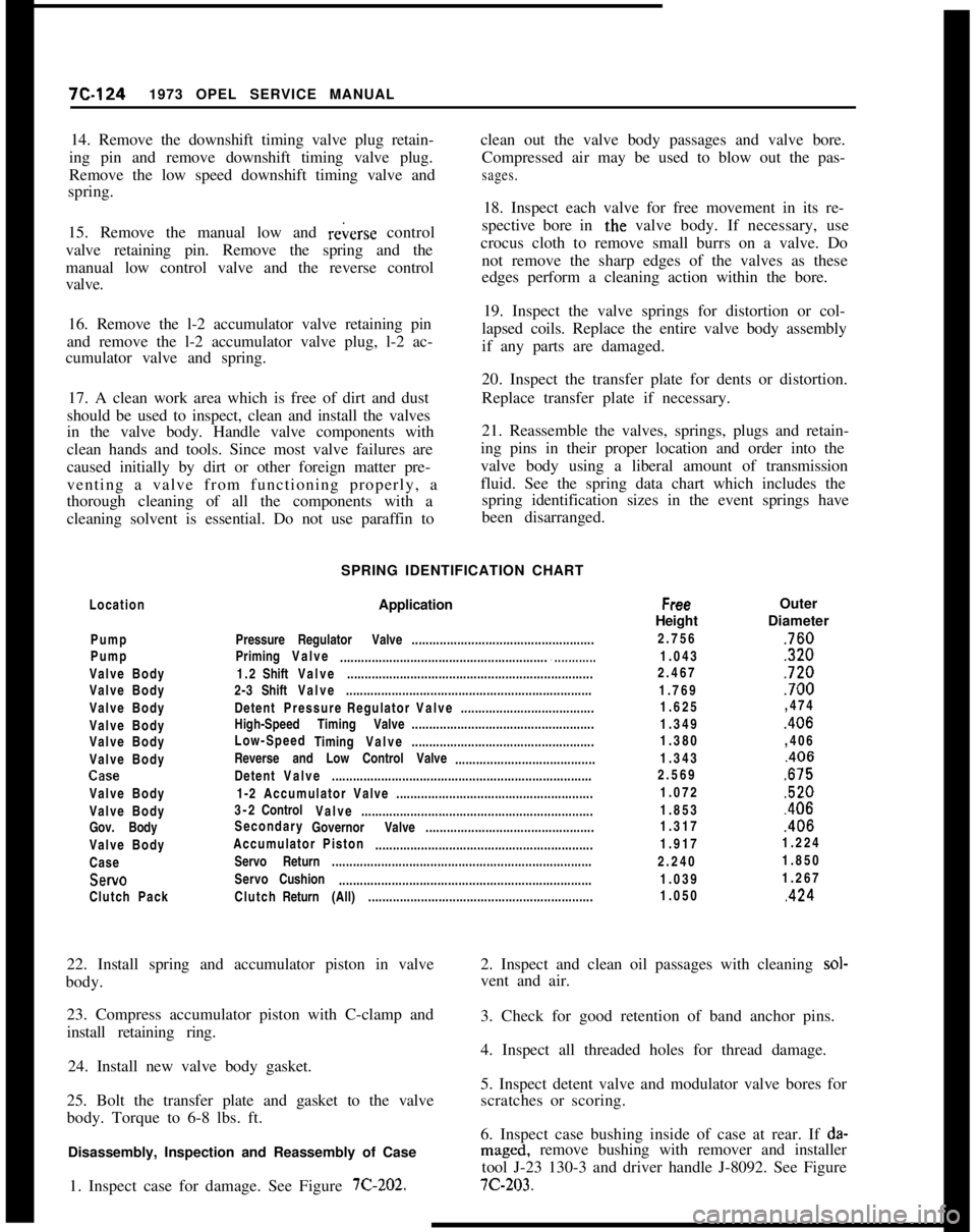
fluid. See the spring data chart which includes the
spring identification sizes in the event springs have
been disarranged.
LocationApplication
PumpPressureRegulator Valve....................................................
PumpPrimingValve
...........................................................
.............Valve Body1.2ShiftValve......................................................................
Valve Body2-3ShiftValve......................................................................
Valve BodyDetentPressureRegulatorValve......................................
Valve BodyHigh-Speed Timing Valve....................................................
Valve BodyLow-Speed
TimingValve....................................................
Valve BodyReverse and Low Control Valve
........................................
CSSDetentValve..........................................................................
Valve Body1-2 Accumulator Valve........................................................
Valve Body3-2Control
Valve..................................................................
Gov. BodySecondary
Governor Valve................................................
Valve BodyAccumulator Piston
..............................................................
CaseServo Return..........................................................................SHVOServoCushion
........................................................................
Clutch PackClutchReturn(All)................................................................ SPRING IDENTIFICATION CHART
FreeOuter
HeightDiameter
2.756
,7601.043
,3202.467
,7201.769
,7001.625,474
1.349
,4061.380,406
1.343
,4062.569
,6751.072
,5201.853
.4061.317
,4061.9171.224
2.2401.850
1.0391.267
1.050
,42422. Install spring and accumulator piston in valve
body.
23. Compress accumulator piston with C-clamp and
install retaining ring.
24. Install new valve body gasket.2. Inspect and clean oil passages with cleaning sol-
vent and air.
3. Check for good retention of band anchor pins.
25. Bolt the transfer plate and gasket to the valve
body. Torque to 6-8 lbs. ft.
Disassembly, Inspection and Reassembly of Case
1. Inspect case for damage. See Figure
7C-202.4. Inspect all threaded holes for thread damage.
5. Inspect detent valve and modulator valve bores for
scratches or scoring.
6. Inspect case bushing inside of case at rear. If
da-maged, remove bushing with remover and installer
tool J-23 130-3 and driver handle J-8092. See Figure
7C-203.
Page 490 of 625
AUTOMATIC TRANSMISSION 7C-129
4. Install reverse clutch cushion plate (wave washer)2. Insert guide pin into oil pump for alignment of
into case.converter housing and lower housing onto pump.Determining Selective Washer Size
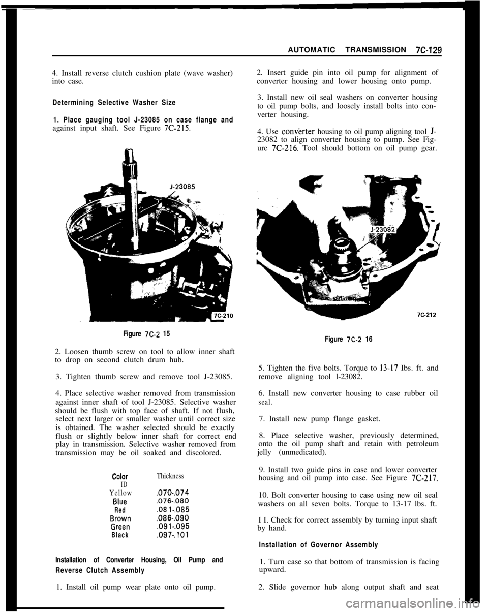
1. Place gauging tool J-23085 on case flange andagainst input shaft. See Figure
7C-215.3. Install new oil seal washers on converter housing
to oil pump bolts, and loosely install bolts into con-
verter housing.
4. Use convkrter housing to oil pump aligning tool J-23082 to align converter housing to pump. See Fig-
ure
7C-216. Tool should bottom on oil pump gear.
Figure 7C-2 152. Loosen thumb screw on tool to allow inner shaft
to drop on second clutch drum hub.
3. Tighten thumb screw and remove tool J-23085.
4. Place selective washer removed from transmission
against inner shaft of tool J-23085. Selective washer
should be flush with top face of shaft. If not flush,
select next larger or smaller washer until correct size
is obtained. The washer selected should be exactly
flush or slightly below inner shaft for correct end
play in transmission. Selective washer removed from
transmission may be oil soaked and discolored.
CObX
ID
Yellow
Blue
Red
BVSNIl
GPX3”
Black
Thickness,070.,074,076.,080
.08 l-.085,086.,090,091.,095
,097.,101
Installation of Converter Housing, Oil Pump and
Reverse Clutch Assembly1. Turn case so that bottom of transmission is facing
upward.
1. Install oil pump wear plate onto oil pump.2. Slide governor hub along output shaft and seat
Figure 7C-2 165. Tighten the five bolts. Torque to
13-17 Ibs. ft. and
remove aligning tool l-23082.
6. Install new converter housing to case rubber oil
seal.7. Install new pump flange gasket.
8. Place selective washer, previously determined,
onto the oil pump shaft and retain with petroleum
jelly (unmedicated).
9. Install two guide pins in case and lower converter
housing and oil pump into case. See Figure
7C-217.10. Bolt converter housing to case using new oil seal
washers on all seven bolts. Torque to 13-17 lbs. ft.
I I. Check for correct assembly by turning input shaft
by hand.
Installation of Governor Assembly
Page 495 of 625
7C-1341973 OPEL SERVICE MANUAL
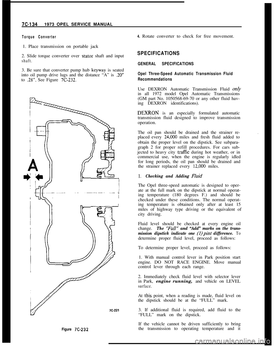
Figure 7C-232
Torque Converter4. Rotate converter to check for free movement.
1. Place transmission on portable jack
2. Slide torque converter over stator shaft and input
shaft.3. Be sure that converter pump hub keyway is seated
into oil pump drive lugs and the distance “A” is
.20”to
.28”. See Figure 7C-232.
SPECIFICATIONS
GENERAL SPECIFICATIONS
Opel Three-Speed Automatic Transmission Fluid
RecommendationsUse DEXRON Automatic Transmission Fluid on/y
in all 1972 model Opel Automatic Transmissions
(GM part No. 1050568-69-70 or any other fluid hav-
ing DEXRON identifications).DEXIRON is an especially formulated automatic
transmission fluid designed to improve transmission
operation.
The oil pan should be drained and the strainer re-
placed every
24,ooO miles and fresh fluid added to
obtain the proper level on the dipstick. See subpara-
graph 2 for proper refill procedures. For cars sub-
jected to heavy city
traff%z during hot weather, or in
commercial use, when the engine is regularly idled
for long periods, the oil pan should be drained and
the strainer replaced every
12,ooO miles.
.
1.Checking and Adding FluidThe Opel three-speed automatic is designed to oper-
ate at the full mark on the dipstick at normal operat-
ing temperature (180 degrees F.) and should be
checked under these conditions. The normal operat-
ing temperature is obtained only after at least 15
miles of highway type driving or the equivalent of
city driving.
Fluid level should be checked at every engine oil
change.
The “FuIl” and “Add” marks on the trans-
mission dipstick indicate one (1)pint
difference. Todetermine proper fluid level, proceed as follows:
To determine proper level, proceed as follows:
1. With manual control lever in Park position start
engine. DO NOT RACE ENGINE. Move manual
control lever through each range.
2. Immediately check fluid level with selector lever
in Park, engine running, and vehicle on LEVEL
surface.At
t,his point, when a reading is made, fluid level on
the dipstick should be at the “FULL” mark.
3. If additional fluid is required, add fluid to the
“FULL” mark on the dipstick.
If the vehicle cannot be driven sufficiently to bring
the transmission to operating temperature and it
Page 497 of 625
7C-1361973 OPEL SERVICE MANUALshould be secured to keep the front wheels in a
straight-ahead position.sand,. mud, or snow, move the selector lever from
“D” to “R” in a repeat pattern while simultaneously
applying moderate pressure to the accelerator. DoRocking Carnot race engine. Avoid spinning wheels when trying
If it becomes necessary to rock the car to free it fromto free the car.
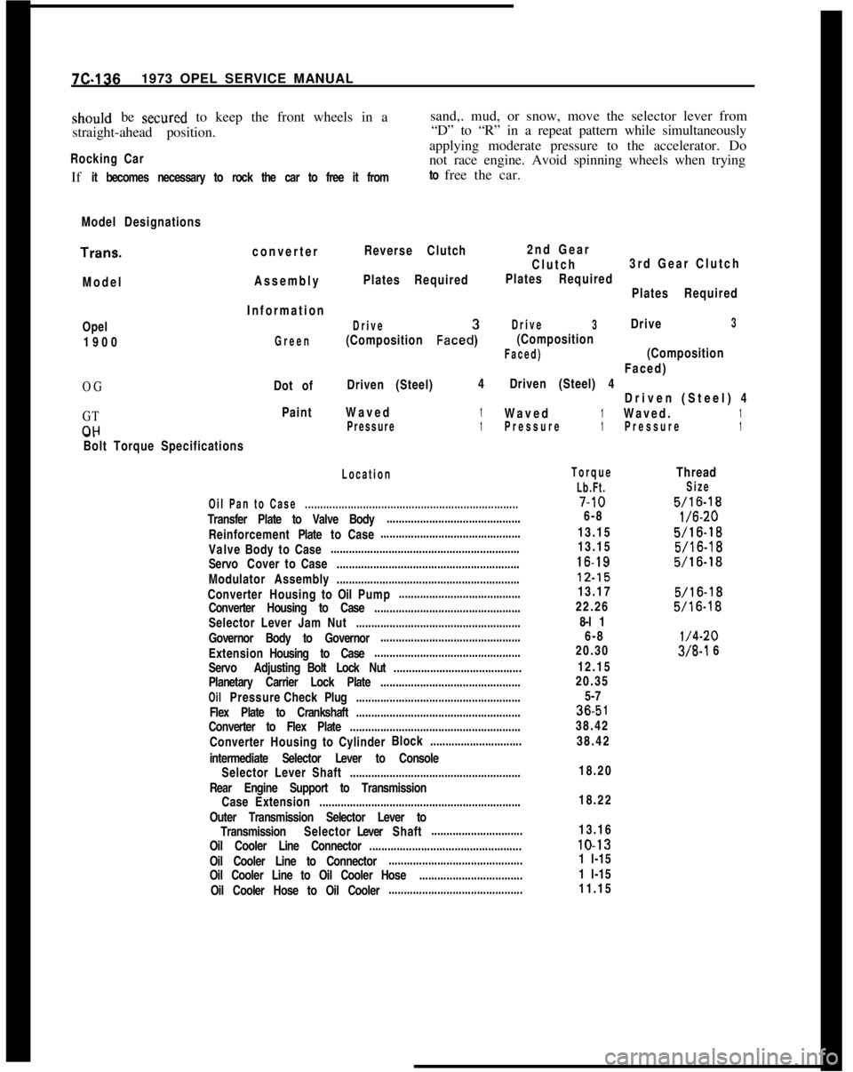
Model DesignationsTrans.
converterReverse Clutch
ModelAssemblyPlates Required2nd Gear
Clutch3rd Gear Clutch
Plates Required
Plates RequiredOpel
1900
OG
GT
CIHInformation
Drive
(Composition Faced:
Drive3Drive3
Green
(Composition
Faced)(CompositionFaced)
Dot ofDriven (Steel)4Driven (Steel) 4
Driven (Steel) 4
PaintWaved1Waved1Waved.1Pressure1Pressure1Pressure1-.
Bolt Torque Specifications
Location
Oil Pan to Case......................................................................Transfer Plate to Valve Body............................................
ReinforcementPlatetoCase..............................................
ValveBodytoCase..............................................................
ServoCovertoCase............................................................
Modulator Assembly............................................................
ConverterHousingtoOilPump........................................
Converter Housing to Case................................................
Selector Lever Jam Nut......................................................
Governor Body to Governor..............................................
ExtensionHousing to Case................................................
Servo AdjustingBolt Lock Nut..........................................
Planetary Carrier Lock Plate..............................................
OilPressureCheckPlug......................................................
Flex Plate to Crankshaft......................................................
Converter to Flex Plate........................................................
ConverterHousingtoCylinderBlock..............................
intermediate Selector Lever to Console
Selector Lever Shaft........................................................
Rear Engine Support to Transmission
CaseExtension..................................................................
Outer Transmission Selector Lever to
TransmissionSelectorLeverShaft..............................
Oil Cooler Line Connector..................................................
Oil Cooler Line to Connector............................................
Oil Cooler Line to Oil Cooler Hose..................................
Oil Cooler Hose to Oil Cooler............................................
Torque
Lb.Ft.7-10
6-8
13.15
13.1516-1812.15
13.17
22.26
8-l 1
6-8
20.30
12.15
20.35
5-736.5
138.42
38.42
Thread
Size
5/16-18
l/6-20
5/16-18
5/16-18
5/16-18
5/16-18
5/16-18
l/4-20
3/8-l 6
18.20
18.22
13.1610-13
1 l-15
1 l-15
11.15
Page 500 of 625

AUTOMATIC TRANSMISSION 75139
SPECIAL TOOLSJ-8763-01
:: J-21369
3.J-8400-1
4.J-3289-20
5.J-23130-3
6.J-8092
7.J-21359
8.J-21426
9.J-2312910. J-7004
11. J-2590-12
12. J-21420-1
13. J-23130-7
14. J-23075
15. J-23 130-S16. J-231306
17. J-23130-1
18. J-21424-9
19.J-21465-17
20.J-23080
21.J-23 130-2
22.J-23082
23.J-23085
24.J-23 100Transmission Holding Fixture
Converter Leak Test Fixture
Cape ChiselHolding Fixture Base
Rear Case Bushing Remover and Installer
Driver Handle
Converter Housing Oil Seal Installer
Extension Housing Oil Seal Installer
Converter Housing Seal Remover
- Without Disassembling Transmission
(Use With J-7004)Slide Hammer
2nd and Reverse Clutch Piston Spring Compressor
Clutch Piston Compressor Adapter
Reaction Sun Gear Drum Bushing Sleeve Installer
Servo and 3rd Clutch Piston Spring Compressor
Oil Pump Bushing Remover
2nd Clutch Drum Bushing Remover and Installer
Oil Pump Bushing Installer
Extension Housing Bushing Remover and Installer (Use with J-8092
Driver Handle)
Converter Housing Bushing Remover and Installer (Use With J-8092)
2nd Clutch Piston Seal Installer
Reaction Sun Gear Drum Bushing Installer
Converter to Oil Pump Alignment Tool
Oil Pump to 2nd Clutch Drum Gauging Tool
Vacuum Modulator Wrench
Page 532 of 625
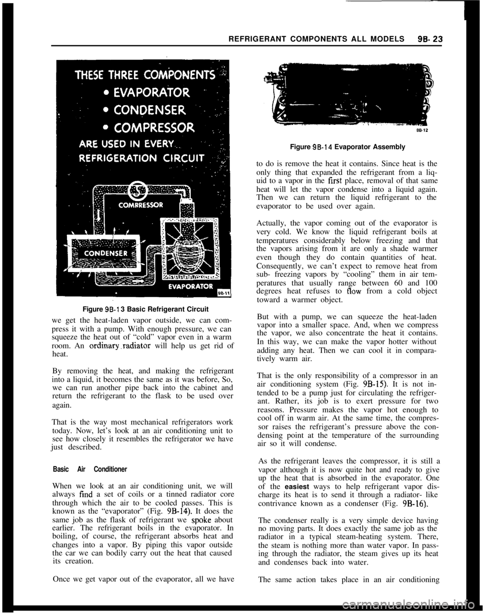
REFRIGERANT COMPONENTS ALL MODELS96.23Figure 96-l 3 Basic Refrigerant Circuit
we get the heat-laden vapor outside, we can com-
press it with a pump. With enough pressure, we can
squeeze the heat out of “cold” vapor even in a warm
room. An ordinary.radiator will help us get rid of
heat.
By removing the heat, and making the refrigerant
into a liquid, it becomes the same as it was before, So,
we can run another pipe back into the cabinet and
return the refrigerant to the flask to be used over
again.
That is the way most mechanical refrigerators work
today. Now, let’s look at an air conditioning unit to
see how closely it resembles the refrigerator we have
just described.
Basic Air ConditionerWhen we look at an air conditioning unit, we will
always find a set of coils or a tinned radiator core
through which the air to be cooled passes. This is
known as the “evaporator” (Fig.
9B-14). It does the
same job as the flask of refrigerant we
spok.e about
earlier. The refrigerant boils in the evaporator. In
boiling, of course, the refrigerant absorbs heat and
changes into a vapor. By piping this vapor outside
the car we can bodily carry out the heat that caused
its creation.
Once we get vapor out of the evaporator, all we haveFigure 98.14 Evaporator Assembly
to do is remove the heat it contains. Since heat is the
only thing that expanded the refrigerant from a liq-
uid to a vapor in the first place, removal of that same
heat will let the vapor condense into a liquid again.
Then we can return the liquid refrigerant to the
evaporator to be used over again.
Actually, the vapor coming out of the evaporator is
very cold. We know the liquid refrigerant boils at
temperatures considerably below freezing and that
the vapors arising from it are only a shade warmer
even though they do contain quantities of heat.
Consequently, we can’t expect to remove heat from
sub- freezing vapors by “cooling” them in air tem-
peratures that usually range between 60 and 100
degrees heat refuses to
flow from a cold object
toward a warmer object.
But with a pump, we can squeeze the heat-laden
vapor into a smaller space. And, when we compress
the vapor, we also concentrate the heat it contains.
In this way, we can make the vapor hotter without
adding any heat. Then we can cool it in compara-
tively warm air.
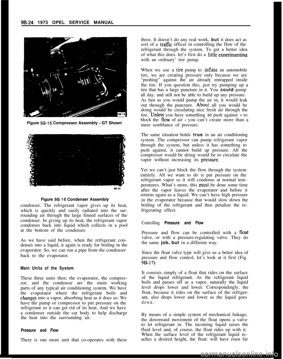
That is the only responsibility of a compressor in an
air conditioning system (Fig.
9B-15). It is not in-
tended to be a pump just for circulating the refriger-
ant. Rather, its job is to exert pressure for two
reasons. Pressure makes the vapor hot enough to
cool off in warm air. At the same time, the compres-
sor raises the refrigerant’s pressure above the con-
densing point at the temperature of the surrounding
air so it will condense.
As the refrigerant leaves the compressor, it is still a
vapor although it is now quite hot and ready to give
up the heat that is absorbed in the evaporator. One
of the easiest ways to help refrigerant vapor dis-
charge its heat is to send it through a radiator- like
contrivance known as a condenser (Fig. 9B-16).
The condenser really is a very simple device having
no moving parts. It does exactly the same job as the
radiator in a typical steam-heating system. There,
the steam is nothing more than water vapor. In pass-
ing through the radiator, the steam gives up its heat
and condenses back into water.
The same action takes place in an air conditioning
Page 533 of 625
9B-24 1973 OPEL SERVICE MANUAL
Figure 9B-15 Compressor Assembly - GT Shown
Figure 3B-16 Condenser Assembly
condenser. The refrigerant vapor gives up its heat,
which is quickly and easily radiated into the sur-
rounding air through the large finned surfaces of the
condenser. In giving up its heat, the refrigerant vapor
condenses back into liquid which collects in a pool
at the bottom of the condenser.
As we have said before, when the refrigerant con-
denses into a liquid, it again is ready for boiling in the
evaporator. So, we can run a pipe from the condenser
back to the evaporator.
Main Units of the SystemThese three units then; the evaporator, the compres-
sor, and the condenser are the main working
parts of any typical air conditioning system. We have
the evaporator where the refrigerant boils andchanges into a vapor, absorbing heat as it does so. We
have the pump or compressor to put pressure on the
refrigerant so it can get rid of its heat. And we have
a condenser outside the car body to help discharge
the heat into the surrounding air.
Pressure and FlowThere is one more unit that co-operates with thesethree. It doesn’t do any real work, but it does act as
sort of a traffic officer in controlling the flow of the
refrigerant through the system. To get a better idea
of what this does. let’s first do a li,ttle exoerimentine
with an ordinary’ tire pump.
When we use a
t,ire pump to Sate an automobile
tire, we are creating pressure only because we are
“pushing” against the air already entrapped inside
the tire. If you question this, just try pumping up a
tire that has a large puncture in it. You could pump
all day, and still not be able to build up any pressure.
As fast as you would pump the air in, it would leak
out through the puncture.
Abou~t all you would be
doing would be circulating nice fresh air through the
tire.
1Jnless you have something lo push against - to
block the tlow of air
- you can’t create more than a
mere semblance of pressure.
The same situation holds true in an air conditioning
system. The compressor can pump refrigerant vapor
through the system, but unless it has something to
push against, it cannot build up pressure. All the
compressor would be doing would be to circulate the
vapor without increasing its
pres,sure.Yet we can’t just block the flow through the system
entirely. All we want to do is put pressure on the
refrigerant vapor so it will condense at normal tem-
peratures. What’s more, this
musi: be done some time
after the vapor leaves the evaporator and before it
returns again as a liquid. We can’t have high pressure
in the evaporator because that would slow down the
boiling of the refrigerant and thus penalize the re-
frigerating effect.
Controlling Pressure and FlowPressure and flow can be controlled with a float
valve, or with a pressure-regulating valve. They do
the same job, but in a different way.
Since the float valve type will give us a better idea of
pressure and flow control, let’s look at it first (Fig.
9B-17).It consists simply of a float that rides on the surface
of the liquid refrigerant. As the refrigerant liquid
boils and passes off as a vapor, naturally the liquid
level drops lower and lower. Correspondingly, the
float, because it rides on the surface of the refriger-
ant, also drops lower and lower as the liquid goes
down.By means of a simple system of mechanical linkage,
the downward movement of the float opens a valve
to let refrigerant in. The incoming liquid raises the
fluid level and, of course, the float rides up with it.
When the surface level of the refrigerant liquid re-
aches a desired height, the float: will have risen far
Page 535 of 625
98-26 1973 OPEL SERVICE MANUAL
greater than the opposing pressure in the power ele-
ment. Therefore, the valve remains closed. When the
compressor is started, it will reduce the pressure and
temperature of the refrigerant in the cooling coil to
a point where the vapor pressure in the power ele-
ment becomes the stronger. The seat then moves off
the orifice and liquid starts to flow through the valve
orifice into the cooling coil.
The purpose of the power element is to help deter-
mine the quantity of liquid that is being metered into
the cooling coil. As the temperature of the low pres-
sure line changes at the bulb, the pressure of
the
vapor in the power element changes, resulting in a
change of the position of the seat. For example, if the
cooling coil gets more liquid than is required, the
temperature of the low pressure line is reduced and
the resultant lowering of the bulb temperature
reduces the pressure of the vapor in the power ele-
ment, allowing the seat to move closer to the orifice.
This immediately reduces the amount of liquid leav-
ing the valve. Under normal operation, the power
element provides accurate control of the quantity of
refrigerant to the cooling coil.
To employ our tire pump analogy once more for
clarity, it is the same situation that would exist if you were inflating a tire with a very slow leak. Providing
you pumped the air into the tire as fast as it leaked
out, you would be able to maintain pressure even
though the air would merely be circulating through the tire and leaking out through the puncture.
To Sum Up
So far, we’ve discussed only what each unit in an air
conditioning system does. We’ve learned that the
evaporator is the unit in which liquid refrigerant
soaks up heat from the air, the compressor is a pump
for squeezing this heat out of the vapor, the con-
denser is a radiator for getting rid of the heat, and the
thermostatic expansion valve is a device for regulat-
ing the pressure on the refrigerant. Now, let’s
find
out how the temperature of the cooled air is con-
trolled.
METHOD OF TEMPERATURE CONTROL
To achieve temperature control, the compressor is
run intermittently, automatically turning on and off
as necessary to maintain proper temperature.
Thermostatic Switch
The compressor can be started and stopped au-
tomatically through the use of an electro-magnetic
clutch and a thermostat affected by variations of temperature.
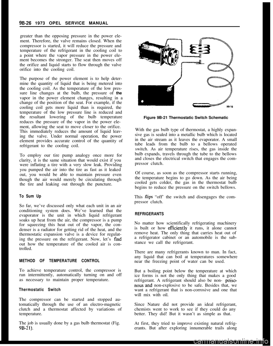
The job is usually done by a gas bulb thermostat (Fig.
9B-21).
Figure 9B-21 Thermostatic Switch Schematic
With the gas bulb type of thermostat, a highly expan-
sive gas is sealed into a metallic bulb which is located
in the air stream as it leaves the evaporator. A small
tube leads from the bulb to a bellows operated switch. As air temperature rises, the gas inside the
bulb expands, travels through the tube to the bellows
and closes the electrical switch that engages the com-
pressor clutch.
Of course, as soon as the compressor starts running,
the temperature begins to go down. As the air being
cooled gets colder, the gas in the thermostat bulb
begins to reduce the pressure on the switch bellows.
This
Ilips “off’ the switch and disengages the com-
pressor clutch.
REFRIGERANTS
No matter how scientifically refrigerating machinery
is built or how
efftciently it runs, it alone cannot
remove heat. The only thing that carries heat out of
a refrigerator cabinet or an automobile is the sub-
stance we call the refrigerant.
There are many refrigerants known to man. In fact,
any liquid that can boil at temperatures somewhere
near the freezing point of water can be used.
But a boiling point below the temperature at which
ice forms is not the only thing that makes a good
refrigerant. A refrigerant should also be non-
poiso-
nowand non-explosive to be safe. Besides that, we
want a refrigerant that is non-corrosive and one that
will mix with oil.
Since Nature did not provide an ideal refrigerant,
chemists went to work to see if they could do any
better. They did! But it wasn’t as simple as that.
At first, they tried to improve existing natural refrig-
erants. But after exploring innumerable trails along