Pump OPEL MANTA 1973 Manual PDF
[x] Cancel search | Manufacturer: OPEL, Model Year: 1973, Model line: MANTA, Model: OPEL MANTA 1973Pages: 625, PDF Size: 17.22 MB
Page 542 of 625
REFRIGERANT COMPONENTS ALL MODELS99- 33
That the attraction of the drying material for mois-
ture is so powerful that if the receiver is left open,
moisture will be drawn in from the outside air.
That just one drop of water added to the refrigerantwill start chemical changes that can result in corro-
sion and eventual breakdown of the chemicals in the
system. Hydrochloric acid is the result of an R-12
mixture with water.
That the smallest amount of air in the refrigeration
system may start reactions that can cause malfunc-
tions.
That the drying agent in the receiver-dehydrator is
Activated Silica Alumina (silica-gel).
That
the inert gas in the expansion valve capillary
line is carbon dioxide.
DESCRIPTION OF AIR CONDITIONING
COMPONENTS
Compressor
The compressor is located in the engine compart-
ment. The purpose of the unit is to draw the low
pressure,gas from the evaporator and compress this
gas into a high temperature, high pressure gas. This
action will result in the refrigerant having a higher
temperature than the surrounding air.
The
cortipressor is of basic double action piston de-
sign. Three horizontal double acting pistons make up
a six cylinder compressor (See Figure
9B-162). The
pistons operate in
l-1/2 inch bore and have a l-1/8
inch stroke. A
wash plate keyed to the shaft drives
the pistons. The shaft is belt driven through a mag-
netic clutch and pulley arrangement. An oil pump
mounted at the rear of the compressor picks up oil
from the
botto’m of the compressor and lubricates the
bearings’and other internal parts of the compressor.
Reed type valves at each end of the compressor open
or close to control the flow of incoming and outgoing refrigerant. Two gas tight passages interconnect
chambers of the front and rear heads so that there is
one common suction port, and one common dis-
charge port. The internal parts of the compressor
function, as follows:
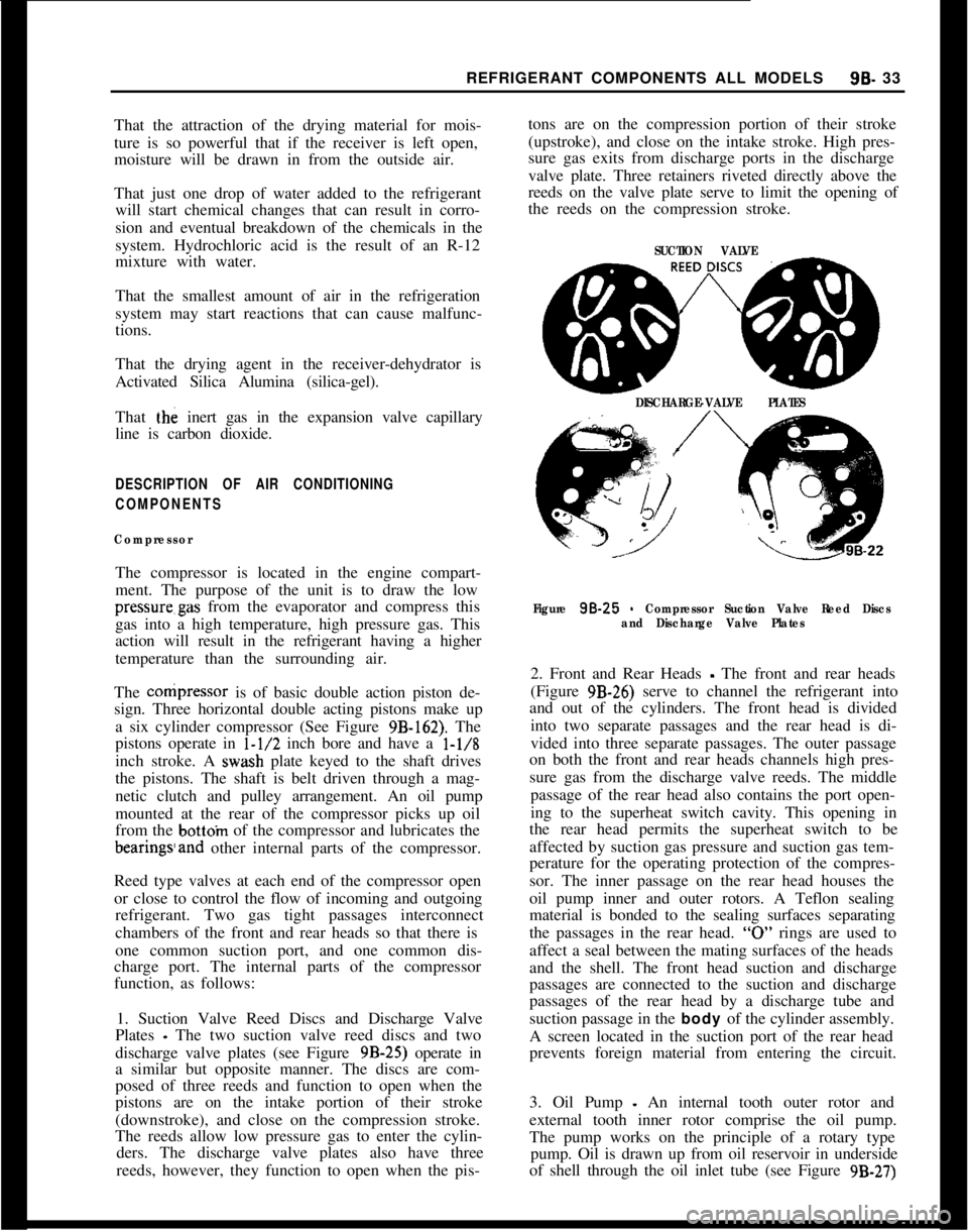
1. Suction Valve Reed Discs and Discharge Valve
Plates
_ The two suction valve reed discs and two
discharge valve plates (see Figure
9B-25) operate in
a similar but opposite manner. The discs are com-
posed of three reeds and function to open when the
pistons are on the intake portion of their stroke
(downstroke), and close on the compression stroke.
The reeds allow low pressure gas to enter the cylin- ders. The discharge valve plates also have three
reeds, however, they function to open when the pis- tons are on the compression portion of their stroke
(upstroke), and close on the intake stroke. High pres-
sure gas exits from discharge ports in the discharge
valve plate. Three retainers riveted directly above the
reeds on the valve plate serve to limit the opening of
the reeds on the compression stroke.
SUCTION VALVE
DISCHARGE-VALVE PLATES
Figure
98-25 - Compressor Suction Valve Reed Discs
and Discharge Valve Plates
2. Front and Rear Heads - The front and rear heads
(Figure
9B-26) serve to channel the refrigerant into
and out of the cylinders. The front head is divided
into two separate passages and the rear head is di-
vided into three separate passages. The outer passage
on both the front and rear heads channels high pres-
sure gas from the discharge valve reeds. The middle
passage of the rear head also contains the port open-
ing to the superheat switch cavity. This opening in
the rear head permits the superheat switch to be
affected by suction gas pressure and suction gas tem-
perature for the operating protection of the compres-
sor. The inner passage on the rear head houses the
oil pump inner and outer rotors. A Teflon sealing
material is bonded to the sealing surfaces separating
the passages in the rear head.
“0” rings are used to
affect a seal between the mating surfaces of the heads
and the shell. The front head suction and discharge
passages are connected to the suction and discharge
passages of the rear head by a discharge tube and
suction passage in the
body of the cylinder assembly.
A screen located in the suction port of the rear head
prevents foreign material from entering the circuit.
3. Oil Pump
- An internal tooth outer rotor and
external tooth inner rotor comprise the oil pump.
The pump works on the principle of a rotary type pump. Oil is drawn up from oil reservoir in underside
of shell through the oil inlet tube (see Figure
9B-27)
Page 551 of 625

98-42 1973 OPEL SERVICE MANUAL
SCHRADER VALVE
ADAPTER J-54201COMPRESSOR(TOP VIEW)[/--DISCHARGE LINE
ILOW PRESSURE\ GAUGE
MANIFOLD AND
-GAUGE SET
J-5725-01
rGAUGE LINES
(5) J-541899-31
Figure 98.41 Set-Up For Discharging System
tion. With the gauge disconnected from the refrigera-
tion system, be sure that the pointer indicates to the
center of zero. Lightly tap gauge a few times to be
sure pointer is not sticking. If necessary, calibrate as
follows:
A. Remove cover from gauge.
B. Holding gauge pointer adjusting screw firmly with
one hand, carefully force pointer in the proper direc-
tion in proper amount to position pointer through
the center of
“0” position. Tap gauge a few times to
be sure pointer is not sticking. Replace gauge cover.
2. If gauge is not already connected to compressor,
connect as follows:
A. Close hand shut-off valves on gauge set by turning
clockwise.B. Remove caps from gauge fittings on the compres-
sor adapter fitting.
C. Attach valve adapter (J-5420) to end of the hosefrom the low pressure gauge and connect thisadapl:er fitted hose to suction gauge fitting.
D. Attach valve adapter (J-9459) to end of hose from
the high pressure gauge and connect this adapter
fitted hose to the discharge fitting.
3. Attach a flexible gauge hose to center fitting of
the gauge set and attach the other end of this hose
to vacuum pump (J-5428-03).
Evacuating Complete System
1. Turn hand shut-off valve on low pressure gauge
of gauge set to full clockwise position.
2. Slowly turn valve on high pressure gauge coun-
terclockwise from full clockwise position, letting any
pressure build-up escape completely. Close high
pressure valve.
3. Check oil level in vacuum pump and, if neces-
sary, add refrigeration oil. Make sure dust cap on
discharge side of pump has been removed.
Page 552 of 625
REFRIGERANT COMPONENTS ALL MODELS9B- 43
4. Start the vacuum pump and slowly open low and
high pressure sides of manifold gauge set to avoid
forcing oil out of refrigeration system and pump,
Pressure is now being reduced on both sides of the
refrigeration system. If oil is blown from the vacuum
pump, it should be refilled to the proper level.
5. Observe low pressure gauge and operate vacuum
pump until gauge shows 28-29 inches vacuum. In all
evacuating procedures, specifications of 28-29 inchesof vacuum is used. This evacuation can only be at-
tained at or near sea level.
For each 1000 feet above sea level where this operat-ion is being-performed, the specification should be
lowered by one inch of mercury vacuum. At 5000
feet elevation, only 23 inches to 24 inches of vacuum
can normally be obtained.
If vacuum cannot be pulled to the minimum specifi-
cation for the respective altitude, it indicates a leak
in the system or gauge connections or a defective
vacuum pump. In this case, it will be necessary to
check for leaks as described under “Leak Testing
Refrigerant System”.
When specified vacuum level (28-29 inches at sea
level) is obtained, continue to run vacuum pump for
ten (10) ‘additional minutes. During these ten (10)
minutes:
A. Prepare for charging the system. If using a charg-
ing station, till charging cylinder. If using manifold
gauge set, make all preparations for charging system
as described under “Disposable Can Method” or
“Refrigerant Drum Method”.
B. Measure oil loss collected as a result of rapid
discharge.
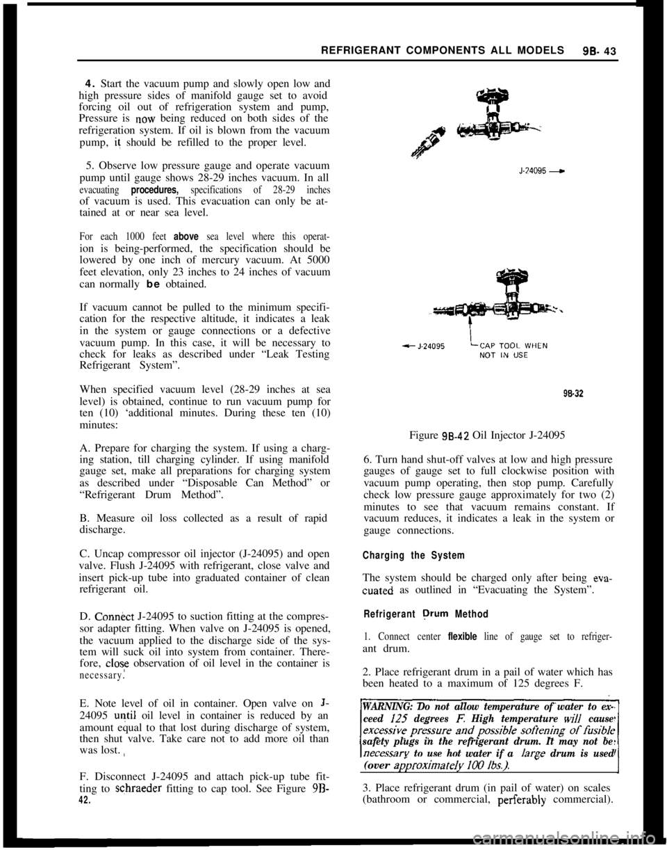
C. Uncap compressor oil injector (J-24095) and open
valve. Flush J-24095 with refrigerant, close valve and
insert pick-up tube into graduated container of clean
refrigerant oil.
D. Con&ct J-24095 to suction fitting at the compres-
sor adapter fitting. When valve on J-24095 is opened,
the vacuum applied to the discharge side of the sys-
tem will suck oil into system from container. There-
fore,
close observation of oil level in the container is
necessary.E. Note level of oil in container. Open valve on
J-24095
u+il oil level in container is reduced by an
amount equal to that lost during discharge of system,
then shut valve. Take care not to add more oil than
was lost. ,,
F. Disconnect J-24095 and attach pick-up tube fit-
ting to schraeder fitting to cap tool. See Figure 9B-
42.J-24095
-98.32
Figure 98.42 Oil Injector J-24095
6. Turn hand shut-off valves at low and high pressure
gauges of gauge set to full clockwise position with
vacuum pump operating, then stop pump. Carefully
check low pressure gauge approximately for two (2)
minutes to see that vacuum remains constant. If
vacuum reduces, it indicates a leak in the system or
gauge connections.
Charging the SystemThe system should be charged only after being eva-cuated as outlined in “Evacuating the System”.
Refrigerant orurn Method
1. Connect center flexible line of gauge set to refriger-ant drum.
2. Place refrigerant drum in a pail of water which has
been heated to a maximum of 125 degrees F.
WARNING: Do not allow temperature of water to ex-
ceed I25
degrees E High temperature will cause
safety plugs in the refrigerant drum. It may not be
necessarv to use hot water if a /arae drum is used(over
ap)roximateIy 100 lbs.).-I3. Place refrigerant drum (in pail of water) on scales
(bathroom or commercial, perferably commercial).
Page 554 of 625

REFRIGERANT COMPONENTS ALL MODELS9t3- 45
B. If system is charged using J-6272-02, close the
valve of opener after all cans are empty. Release the locking lever and discard the three (3) empty cans.
If this tool will be used to complete the charge with
additional cans to provide the required refrigerant
charge, leave the empty cans in position, locate one
full can and lock the lever into place. These empty
cans balance the assembly and prevent the loss of
refrigerant through the open “series” passage. Align
the pierced hole in the empty can with the punch in
the cover of the tool.
If the J-6271 valve for single cans is available, com-
plete charging as explained in 4a above.
5. Close high side valve on manifold gauge set,
WARNING: Prior to starting up engine, the high side
valve on the charging manifold must be closed due
to excessive pressure
bui/d-up which can result in
bursting of the container(s) causing serious injury. If
you are inexperienced in the use of this procedure, seek professional assistance.
6. Operate engine at 2000 RPM with temperature
control knob at full cold position and blower speed
on Max Hi. If air inlet temperature at the condenser
is below 70 degrees F. when this check is made,
bubbles may appear, even though the proper amount
of refrigerant is in the system. Air inlet temperature
must be 70 degrees F. or above to make an accurate
check.
7. When refrigerant has been installed, continue to
operate system and test for proper operation as ou-
tlined
under “Operational Test”.
8. When satisfied that the air conditioning system
is operating properly, stop engine, remove gauge set
and replace protective caps on suction and discharge
fittings.
from thegauge fitting to prevent damage-or injury to
personnel.
9. Using a leak detector, check complete system for
leaks.
Charging Station Method
INSTALLING J-8393-02
-
1. Be ceitain compressor hand shut-off valves to
gauge fittings are closed (counterclockwise).
2. Be certain all valves on charging station are
closed.
3. Connect high pressure gauge line to compressor
high pressure gauge fitting.
4. Turn high pressure hand shut-off valve one turn
clockwise, and high pressure control one turn coun-
terclockwise (open). Crack open low pressure con-
trol and allow refrigerant gas to hiss from low
pressure gauge line for three seconds, then connect
low pressure gauge line to low pressure gauge fitting
on compressor adapter fitting. (Place J-9459 adapter
on hose, then attach adapter to gauge fitting.)
FILLING CHARGING CYLINDER
1. Open Control valve on refrigerant container.
2. Open valve on bottom of charging cylinder, al-
lowing refrigerant to enter cylinder.
3. Bleed charging cylinder to valve (behind control
panel) only as required to allow refrigerant to enter
cylinder. When refrigerant reaches desired charge
level, close valve at bottom of charging cylinder and
be certain cylinder bleed valve is closed securely.
While filling the cylinder, it will be necessary to close
the bleed valve periodically to allow boiling to sub-
side so that refrigerant level in the charging cylinder
can be accurately read.
CHARGING THE SYSTEM USING J-8393-02
1. With charging station connected, as previously
described, remove low pressure gauge line at com-
pressor adapter fitting.
2. Crack open high and low pressure control valves
on station and allow refrigerant gas to purge from
system. Purge slowly enough so, that oil does not
escape from system along with refrigerant.
3. When refrigerant flow nearly stops, connect low
pressure gauge line to
compress& adapter fitting.
4. Turn on vacuum pump and open vacuum control
valve.
5. With system purged as
abovk, run pump until
26-28 inches of vacuum is obtained Continue to run
pump for 15 minutes after the system reaches 26-28
inches vacuum.
In all evacuating procedures, the specification of
26.
28 inches of mercury vacuum is used. These figures
are only attainable at or near sea level. For each 1000
feet above sea level where this operation is being
performed, the specifications should be lowered by 1
inch. For example, at 5000 feet elevation, only 21 to
23 inches vacuum can normally be obtained.
6. If 26-28 inches vacuum (corrected to sea level)
cannot be obtained, close vacuum: control valve and
Page 555 of 625
98-46 1973 OPEL SERVICE MANUAL
shut off vacuum pump. Open refrigerant control
valve and allow some refrigerant to enter system.
Locate and repair all leaks.
7. After evacuating for 15 minutes, add l/2 lb. of
refrigerant to system. Purge this
l/2 lb. and reevacu-
ate for 15 minutes. This second evacuation is to be
certain that as much contamination is removed from
the system as possible.
8. Only after evacuating as above, system is ready
for charging. Note reading on sight glass of charging
cylinder. If it does not contain a sufficient amount
for a full charge, till to proper level.
9. Close low pressure valve on charging station.
Fully open station refrigerant control valve and al-
low all liquid refrigerant to enter system. When full
charge of refrigerant has entered system, turn off
refrigerant control valve and close both hand shut-
off valves.
10. If full charge of refrigerant will not enter system,
close high pressure control and refrigerant control
valves. Start engine and run at low idle with com-
pressor operating. Crack refrigerant control valve
and low pressure control on station. Watch low side
gauge and keep gauge below 50 psi by regulating
refrigerant control valve. Closing valve will lower
pressure. This is to prevent liquid refrigerant from
reaching the compressor while the compressor is op-
erating. When required charge has entered system,
close refrigerant control valve and close low pressure
control.
11. System is now charged and should be perform-
ance- tested before removing gauges.
Adding Refrigerant
The following procedure should be used in adding
small amounts of refrigerant that may have been lost
by leaks or while opening system for servicing the
compressor. Before adding refrigerent to replace that
lost by leaks, check for evidence of oil loss and add
oil if necessary.
This procedure will only apply if the air inlet temper-
ature is above 70 degrees F. at the condenser.
1. Remove caps from compressor gauge fittings.
Attach gauge set to gauge fittings, making sure
adapter (J- 5420) is between low pressure gauge hose
and suction gauge fitting, and J-9459 is between high
pressure gauge hose and discharge gauge fitting.
2. Start engine, turn air conditioning temperature
control knob to full cold position, blower switch to
Max Hi. Operate for ten
(IO) minutes at 2000 RPM
to stabilize system.
3. Observe the refrigerant through the sight glasscover of receiver-dehydrator with the system operat-
ing,
IO see if there are any bubbles evident.
a. If no bubbles are evident, then bleed system slowly
through the discharge valve until bubbles appear in
the receiver-dehydrator. Add 1 lb. of refrigerant as
explained under “Charging the
ISystem”.b. If bubbles are visible in the receiver-dehydrator
with the temperature control krlob in the full cold
position and the blower at MAX speed, it indicates
a partial or complete plug in a line, a shortage of
refrigerant, or both. Correct condition. Add refriger-
ant
u~ntil the sight glass clears, then add another 1 lb.
of refrigerant.
4. Attach flexible hose from center fitting of gauge
set loosely to refrigerant drum or on disposable can
valvxs. Open high and low pressure valves on the
gauge set slightly to purge pressure gauge lines of air.
Tighten fitting of refrigerant drum or can when satis-
fied ihat all air has been removed from gauge lines.
Close (clockwise) both hand shut-off valves or gauge
set.5. Partially charge system.
REFRIGERANT DRUM METHOD:
A. Place pail containing hot water that does not have
a temperature exceeding 125 degrees F. on scales,
place refrigerant drum in pa” containing water, note
weig,ht and only open low pressure valve on gauge
set.B. Start engine, turn temperature control knob to full
cold position and place blower switch in Max Hi.
Operate engine for 10 minutes at 2000 RPM to sta-
bilize system.
C. With compressor operating, slowly open valve on
refrigerant drum and allow refrigerant to flow into
system (through manifold gauge set) until liquid in-
dicator clears up and immediately shut off valve ai
gauge set or on refrigerant drum. Check weight of
refrigerant drum and pail of water. Then slowly open
valve on gauge set (or refrigerant drum) and add one
more lb. of refrigerant. Note total amount of refriger-
ant added.
DISPOSABLE CAN METHOD:
A. Make sure the outlet valve on the J-6271 valve is
fully clockwise and attach the J-6271 to a 1 lb. can
of refrigerant by backing off the valve from the top
of the retainer, slipping the valve onto the can and
turning the valve into the retainer until tight. DO
NOT accidentally open outlet valve during this oper-
ation, as turning the valve into the retainer punctures
the top of the can to make it ready for charging.
.
Page 578 of 625

REFRIGERANT COMPONENTS ALL MODELS96.69
J-9481\J-8092
/BEARING
Disassembly of Rear Head, Oil Pump, Rear
Discharge Valve Plate, and Rear Suction Valve
Reed Disc
If compressor is not going to be disassembled any
further than removal of rear head, oil pump, rear
discharge valve plate, or rear suction valve reed disc,
omit Steps “1, 2 and
4”.
1. Disassemble clutch drive plate and shaft seal.
2. Disassemble pulley assembly, and coil and hous-
ing assembly.
3. Clean surface of compressor shell and dry with
compressed air.
4. Remove compressor from holding fixture
(J-
9396), unscrew drain screw. Drain, measure and re-
cord amount of oil in compressor.
Figure
98-121 Installing Bearing into Pulley Assembly 5. Reinstall compressor in holding fixture (J-9396)
positioned as shown in Figure 9B-123.
Figure SB-122 Installing Pulley Assembly
6. Reassemble clutch drive plate.
DISASSEMBLY AND REASSEMBLY OF INTERNAL
PARTS OF COMPRESSOR AND LEAK TESTING
COMPRESSOR
A clean work area and a place for each part removed
is required to properly disassemble and reassemble compressor. The internal parts of the compressor
must be kept free of dirt or foreign material.
When working with compressor, under no circum-
stances should compressor be rested on pulley end.
PRESSURE
Figure 96.123 Compressor Installed in Holding
Fixture
6. Unscrew and discard four lock nuts from rear of
compressor, and lift off rear head by tapping it with
a mallet. If Teflon sealing surface is damaged (see
Figure
9B-124), replace rear head. Clean or replace
suction screen as necessary.
7. Pencil mark top side of both oil pump rotors and
lift out rotors. Replace both oil pump inner and outer
rotors if one or both are damaged or worn.
Page 587 of 625

98-78 1973 OPEL SERVICE MANUAL
der assembly and align with dowel pins, suction poitand discharge port (see Figure
9B-153).2. Assemble front discharge valve plate to front of
cylinder assembly and align with dowel pins.
3. Coat sealing surfaces on front head (see Figure9B- 154) with No. !?5 viscosity cdl.
Figure 98.152 Installing Discharge Tube O-Ring and
BushingFigure 98.154 Placing Front Head on Cylinder
Assembly4. Murk with pencil on side of front head the loca-
tion of dowel pin holes (see Figure 9B-154), align
front head with dowel pins, and tap head lightly with
mallet to seat on cylinder assembly.
5. Place new shell to head
“0” ring on shoulder of
front head (see Figure 9B-155) and liberally coat
“0” ring and front head sealing surface with No. 525
viscosity oil.
6. Install she11 in holding fixture (J-9396) and posi-
tion so that rear studs of shell are up. Coat inside
surface of shell with No. 525 viscosity oil.
Figure 9B-153 Front Suction Valve Reed Disc
installed7. Reassemble, as a unit, cylinder assembly and
front head into the shell. See Figure 9B-156. Extreme
care must be used to prevent she11 to head
“0” ring
seal from being damaged.
Reassembly of Rear Suction Valve Reed Disc, Rear
Discharge Valve Plate, Oil Pump and Rear Head
1. Rotate the cylinder assembly and front head until
Page 588 of 625

REFRIGERANT COMPONENTS ALL MODELS9B- 79
HELL TO HEAD
O-RING(BE SURE
INSIDE SHELL
GRASP FRON
Figure SB-156 Installing Front Head and Cylinder
Assembly in Shell
Figure
96-155 Shell To Front Head O-Ring Installment
the hole for the oil inlet tube in the cylinder assembly
is aligned with the reservoir hole in the shell, and
reassemble the oil inlet tube and
“0” ring.
2. Assemble suction reed valve disc to rear of cylin-
der assembly and align with dowel pins, suction port,
and discharge port of cylinder assembly.
3. Assemble rear discharge valve plate to rear of
cylinder assembly and align with dowel pins.
4. Reassemble inner and outer oil pump rotors so
that the sides previously identified are in their origi-
nal location, and then position oil pump outer rotor
as shown in Figure
9B-157.5. Generously coat with No. 525 viscosity oil new
“0” ring and install in shell (see Figure shell to head
9B-157).6. Coat Teflon sealing surface of rear head with No.
525 viscosity oil, mark with pencil on side of rear
head the lpcation of the dowel pin holes and reassem-
ble onto compressor.Figure
98.157 Positioning Oil Pump Outer Rotor
It may be necessary to repositipn oil pump outer
rotor slightly in order to install rear head. In addi-
tion, if dowel pins do not engage’ holes in rear head,
grasp front head and rotate cylinder assembly
slightly (see Figure
9B-158).7. Assemble new nuts to threaded shell studs and
torque to 10 lb. ft. If pressure relief valve has been
removed, reassemble using a
riew pressure relief
valve gasket.
8. Reassemble new lubricated suction and discharge
Page 594 of 625

REFRIGERANT COMPONENTS ALL MODELSSB- 85
123 45 6 7a910 11 12 131415 lb1718 19
_202122232425 26 272a2930313233 34 35 3b
I. Rear Head13. Coil and Housing
Assemblv
2. Rear Head to Shell “0” Ring
3. Rear Discharge Valve Plate14. coil Housiq Retaining Ring25. Thrust Race
4. Rear Suction Reed Plate
15. Pulley and Bearing Assembly26. Thrust &zarin~27.16. Pulley BearingThrust Race
28.
5.
PistonRingCompressor Shell6. Piston Drive Ball17. Pulley Bearing Retainer Ring
18. Pulley and
Bearing Retainer Ring29. Cylinder Assembh30.Shaft Seal
7. Ball Seat (Shae Disc)
8. Piston
19. Clutch Hub and Drive Plate Assembly 31. Shaft Seal Seat “0” Rjn820. Oil Pump Gears
32. Shaft Seal sear
9. Front Suction Reed Plate
10. Front Discharge Valve Plate21. Mainshaft
Bearing (Rear)
22. Oil inlet Tube “0” Ring33. Shaft Seal Seat Rrrainer Ring
11. Fr&t Head to Shell “0” Rin8 23. Oil Inlet Tube34. Spacer
12. Front Head24. Wobble
(Skash) Plate and Mainshaft35. Clutch flub Retainer Ring36:Shaft Nut
Assembly98.131Figure 98.162 Compressor Section View
Page 597 of 625
AIR CONDITIONER SYSTEM -OPEL 1900 - MANTASB- 89
cJ 6084
J
14OVSJ
5428.03
,J 23390
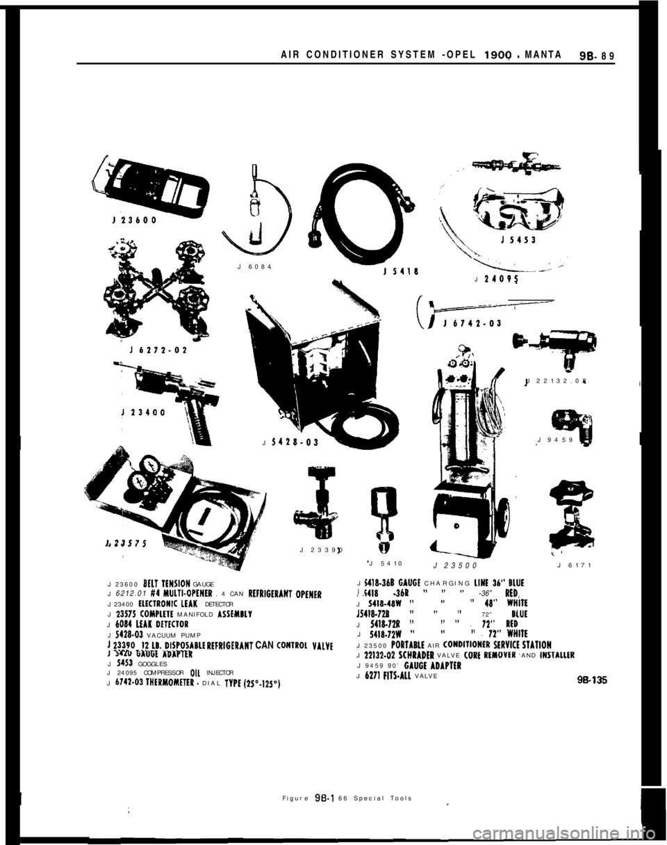
J 23600 BELT IENSION GAUGE
J 6212.01 #4 MlJLTI.OPtNtR . 4 CAN RtFRIGtRANT OPENER
J 23400
tlKlRONIC LEAK DETECTOR
J 23575 COMPLHE MANIFOLD ASSfYBLY
J 6034 LEAK WtClORJ 5418-03 VACUUM PUMP
! ?!!~O~!~~~..~I~poIIRL~ REFRIGERANT CAN CONIROL VALVEI WI" 6A"Gt ADAPTEK
J 5453 GOGGLES
J 24095 COMPRESSOR OIL INJECTOR
J 6742.03 IHtRMOMETER
- DIAL TYPE (2S”.lZ5~)J 22132.02
I
J 9459
1J 5410
J 23500J 6171
141%360 GAUGt CHARGING LINE 36” BLUEi418 -36R ” ” ” -36” RED, J!I I, .J 5418.48W ””” 48” WHIIEJ5418.728
” ” ” 72” BLUI
J 5418.72s ”” I’ . 11” RtD
J 5418.7ZW ””” . 72” WWllt
J 23500 PORlARLt AIR ~ONDIlIONtR SERVlCt STAllON
J 22132.D2 SCWRADER VALVE
J 6271 FIlS.ALL VALVE98136I
IFigure 96-l 66 Special Tools