Push PEUGEOT LANDTREK 2023 Owners Manual
[x] Cancel search | Manufacturer: PEUGEOT, Model Year: 2023, Model line: LANDTREK, Model: PEUGEOT LANDTREK 2023Pages: 164, PDF Size: 6.1 MB
Page 32 of 164
30
Ease of use and comfort
Correct driving position
For safety reasons, adjustments must
only be made when the vehicle is
stationary.
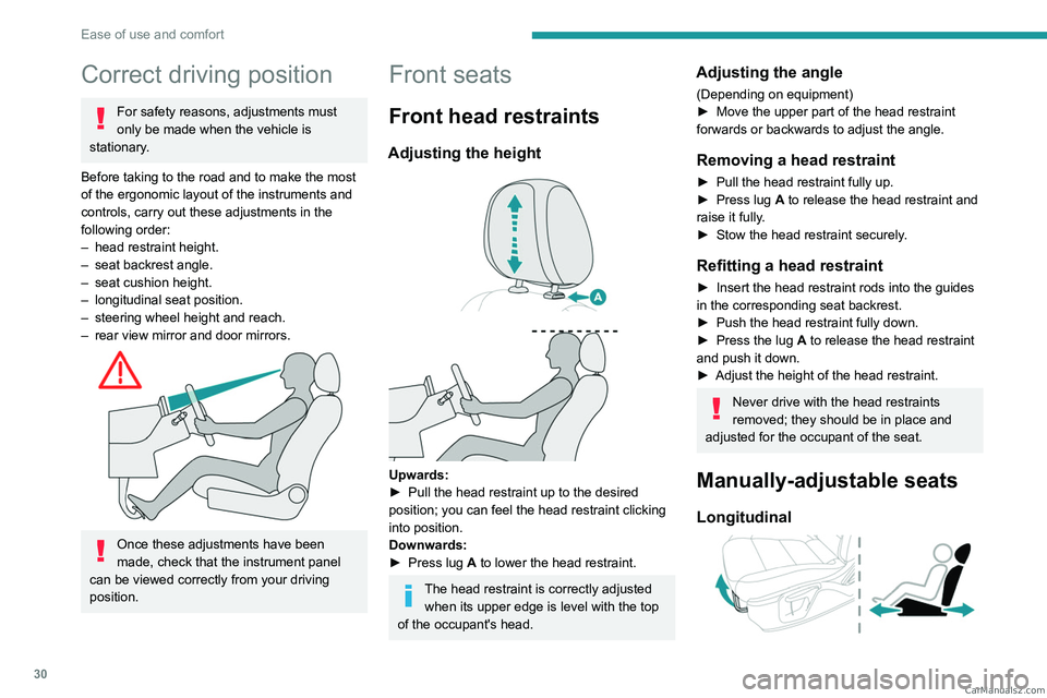
Before taking to the road and to make the most
of the ergonomic layout of the instruments and
controls, carry out these adjustments in the
following order:
–
head restraint height.
–
seat backrest angle.
–
seat cushion height.
–
longitudinal seat position.
–
steering wheel height and reach.
–
rear view mirror and door mirrors.
Once these adjustments have been
made, check that the instrument panel
can be viewed correctly from your driving
position.
Front seats
Front head restraints
Adjusting the height
Upwards:
► Pull the head restraint up to the desired
position; you can feel the head restraint clicking
into position.
Downwards:
►
Press lug
A to lower the head restraint.
The head restraint is correctly adjusted when its upper edge is level with the top
of the occupant's head.
Adjusting the angle
(Depending on equipment)
► Move the upper part of the head restraint
forwards or backwards to adjust the angle.
Removing a head restraint
► Pull the head restraint fully up.
► Press lug A to release the head restraint and
raise it fully.
►
Stow the head restraint securely
.
Refitting a head restraint
► Insert the head restraint rods into the guides
in the corresponding seat backrest.
►
Push the head restraint fully down.
►
Press the lug
A to release the head restraint
and push it down.
►
Adjust the height of the head restraint.
Never drive with the head restraints
removed; they should be in place and
adjusted for the occupant of the seat.
Manually-adjustable seats
Longitudinal
CarM an uals 2 .c o m
Page 33 of 164

31
Ease of use and comfort
3► Raise the control bar and slide the seat
forwards or backwards.
►
Release the control bar to lock the seat in
position on one of the notches.
Backrest angle
► Pull the control all the way up and tilt the
backrest forwards or backwards to adjust it.
Height
(driver only)
► Pull the control upwards to raise or push it
downwards to lower , until you obtain the position
required.
Electrically-adjustable seats
Longitudinal
► Push the control forwards or backwards to
slide the seat.
Backrest angle
► Tilt the control forwards or rearwards.
Cushion height and angle
(driver only)
► Tilt the rear of the control upwards or
downwards to obtain the required height and
angle.
Electric lumbar adjustment
(driver only)
► Press and hold the front or rear of the
control to increase or reduce the lumbar
support.
2-seat front bench seat
It includes 2 fixed cushions with 2 independent
backrests (adjustable and foldable in the table
position).
The backrest of the seat located next to the
driver, once in the table position, can also be
used as an armrest and has 2 cup/can holders
and a support strap.
For more information on the Seat belts,
refer to the corresponding section. CarM an uals 2 .c o m
Page 34 of 164
32
Ease of use and comfort
Folding the backrests
The backrests must only be operated with the vehicle stationary.
While driving, having a passenger in the rear,
behind the front benchseat is prohibited if the
benchseat backrests are tilted.
When sharp deceleration occurs, objects
placed on the folded backrest can turn into
projectiles.
Preliminary operations:
►
Lower the head restraints.
►
Check that no person or object will interfere
with folding down the backrests (clothing,
luggage, etc.).
►
Check that the outer seat belt is properly
tensioned along the pillars, the central belt is
stowed and the tongues of the belts are correctly
in the stowed position.
Deactivation of the front passenger
airbag is recommended.
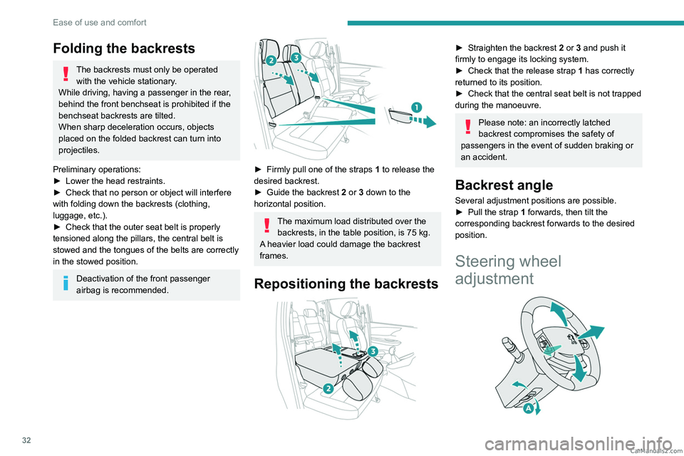
► Firmly pull one of the straps 1 to release the
desired backrest.
►
Guide the backrest
2 or 3 down to the
horizontal position.
The maximum load distributed over the backrests, in the table position, is 75 kg.
A heavier load could damage the backrest
frames.
Repositioning the backrests
► Straighten the backrest 2 or 3 and push it
firmly to engage its locking system.
►
Check that the release strap 1
has correctly
returned to its position.
►
Check that the central seat belt is not trapped
during the manoeuvre.
Please note: an incorrectly latched
backrest compromises the safety of
passengers in the event of sudden braking or
an accident.
Backrest angle
Several adjustment positions are possible.
► Pull the strap 1 forwards, then tilt the
corresponding backrest forwards to the desired
position.
Steering wheel
adjustment
CarM an uals 2 .c o m
Page 35 of 164
33
Ease of use and comfort
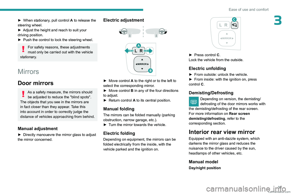
3► When stationary, pull control A to release the
steering wheel.
►
Adjust the height and reach to suit your
driving position.
►
Push the control to lock the steering wheel.
For safety reasons, these adjustments
must only be carried out with the vehicle
stationary.
Mirrors
Door mirrors
As a safety measure, the mirrors should be adjusted to reduce the "blind spots".
The objects that you see in the mirrors are
in fact closer than they appear. Take this
into account in order to correctly judge the
distance of vehicles approaching from behind.
Manual adjustment
► Directly manouevre the mirror glass to adjust
the mirror concerned.
Electric adjustment
► Move control A to the right or to the left to
select the corresponding mirror.
►
Move control
B in any of the four directions
to adjust.
►
Return control A
to its central position.
Manual folding
The mirrors can be folded manually (parking
obstruction, narrow garage, etc.).
►
T
urn the mirror towards the vehicle.
Electric folding
Depending on equipment, the mirrors can be
folded electrically from the inside, with the
vehicle parked and the ignition on.
► Press control C.
Lock the vehicle from the outside.
Electric unfolding
► From outside: unlock the vehicle.
► From inside: with the ignition on, press
control
C.
Demisting/Defrosting
Depending on version, the demisting/
defrosting of the door mirrors works with
the demisting/defrosting of the rear screen.
For more information on Rear screen
demisting/defrosting , refer to the
corresponding section.
Interior rear view mirror
Equipped with an anti-dazzle system, which
darkens the mirror glass and reduces the
nuisance to the driver caused by the sun,
headlamps of other vehicles, etc.
Manual model
Day/night position CarM an uals 2 .c o m
Page 36 of 164
34
Ease of use and comfort
► Pull the lever to change to the anti-dazzle
"night" position.
►
Push the lever to change to the normal "day"
position.
Adjustment
►
Adjust the mirror to the normal "day" position.
Rear bench seat
Bench seat with folding cushions (giving access
to storage compartments) and split folding
backrests (2/3-1/3).
Rear head restraints
High position (use):
► Pull the head restraint fully up.
Low position (stowing; when the seats are not
in use):
►
Press the lug
A to release the head restraint
and push it down.
The rear head restraints can be removed.
Removing a head restraint
► Pull the head restraint fully up.
► Press the lug A to release the head restraint
and remove it completely.
►
Store the head restraint.
Refitting a head restraint
► Insert the head restraint rods into the guides
in the corresponding seat backrest.
►
Push the head restraint down as far as it will
go.
►
Press the lug
A to release the head restraint
and push it fully down.
Never drive with passengers seated at
the rear when the head restraints are
removed; the head restraints should be in
place and in the high position.
The head restraint for the centre seat
and those for the outer seats are not
interchangeable.
Folding the backrests
Manoeuvring the backrests should only
be done when the vehicle is stationary.
First steps:
► Lower the head restraints.
►
If necessary
, move the front seats forward.
►
Check
that no person or object might interfere
with the folding of the backrests (e.g.
clothing,
luggage).
►
Check that the seat belts are free, not
engaged in the buckles. Release them so that
the backrest can be moved.
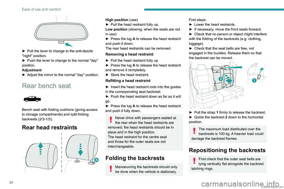
► Pull the strap 1 firmly to release the backrest.
► Guide the backrest 2 down to the horizontal
position.
The maximum load distributed over the backrests is 100 kg. A heavier load could
damage the backrest frames.
Repositioning the backrests
First check that the outer seat belts are
lying vertically flat alongside the backrest
latching rings. CarM an uals 2 .c o m
Page 37 of 164

35
Ease of use and comfort
3
► Put the backrest 2 in the upright position and
push it firmly to latch it home.
►
Check that the release strap 1
has correctly
returned to its position.
►
Ensure that the outer seat belts were not
trapped during the operation.
Please note: an incorrectly latched
backrest compromises the safety of
passengers in the event of sudden braking or
an accident.
Tilting the seat cushions
Manoeuvring the seat cushions must
only be done with the vehicle stationary.
First steps:
►
If necessary
, move the front seats forward. ►
Check that no person or object could interfere
with the tilting of the seat cushions (clothing,
luggage, etc.).
►
Check that the seat belts are free, not
engaged in the buckles.
► Take strap 1 out of the case (located under
the seat cushion) and pull it firmly to release the
seat cushion.
►
T
ilt the seat cushion 2 to the vertical position
(against the backrest).
► Attach hook 3 of strap 1 onto the head
restraint rod.
Under-seat storage boxes
Storage boxes are accessible under the
cushions of the rear bench seat.
► With the cushion raised, lift the carpet to
access the storage compartments and the tool
kit (depending on version). CarM an uals 2 .c o m
Page 38 of 164

36
Ease of use and comfort
For more information on the Tool kit,
refer to the corresponding section.
Repositioning the seat
cushions
Before lowering the seat cushion to the
normal position, make sure that you take
the seat belt buckle and hold it during the
operation.
► Remove hook 3 from the head restraint rod.
► Guide seat cushion 2
to the horizontal
position and push it firmly to lock it.
►
Check that the release strap 1
has correctly
returned to its position, then store it in its case.
►
Check that the seat belt buckles did not slip
under the seat cushions during the manoeuvre.
Heating and Ventilation
Air intake
The air circulating in the passenger compartment
is filtered and originates either from the
exterior, via the grille located at the base of the
windscreen, or from the inside in air recirculation
mode.
Controls
The controls are grouped together on the centre
console panel.
Air distribution
1. Windscreen demisting/de-icing vents
2. Front side window demisting/de-icing vents
3. Adjustable and closable side air vents
4. Adjustable and closable central air vents
5. Air outlets to the front footwells
6.Air outlets to the rear footwells (depending on
version)
7. Adjustable and closable air vents, with blower
(depending on version)
Advice
Using the ventilation and air
conditioning system
►
T
o ensure that air is distributed evenly,
keep the external air intake grilles at the base
of the windscreen, the nozzles, the vents, the
air outlets and the air extractor in the boot
free from obstructions.
►
Do not cover the sunshine sensor located
on the dashboard; this sensor is used to
regulate the automatic air conditioning
system.
►
Operate the air conditioning system for at
least 5 to 10 minutes once or twice a month to
keep it in good working order
.
►
If the system does not produce cold air
,
switch it off and contact a PEUGEOT dealer
or a qualified workshop.
When towing a large load on a steep gradient
in high temperatures, switching off the air
conditioning increases the available engine
power, enhancing the towing capacity.
Avoid driving for too long with the ventilation off or with prolonged operation CarM an uals 2 .c o m
Page 47 of 164

45
Ease of use and comfort
3Load retaining partition
On the structure of the loading bay, behind the
rear window, a vertical separation protects the
driver and passengers against the risk of load
movement.
Bars separate the loading area from the cab.
Retractable hooks, integrated into the upper bar,
are used to secure the loads in the loading bay.
Recommendations on
loading
The weight of the load must comply with the Gross Train Weight (GTW).
For more information on Engine technical
data and towed loads , refer to the
corresponding section.
Make sure that the size, shape and
volume of the loads carried are
compatible with the highway code and safety
regulations and do not impair the driver’s field
of vision.
The load must be evenly distributed in the loading area so as not to interfere
with driving the vehicle.
Place the load close to the side wall panels,
or push it against the side wall panels
between the wheel arches.
However, it is recommended that heavy
objects are placed as close to the cab as
possible as a precaution in case of sharp
braking.
Secure all loads firmly using the stowing
rings present on the side panels of the
loading bay.
For more information on the Loading bay
fittings, and in particular on the stowing
rings, refer to the corresponding section.
To avoid the risk of injury or accident, the load must be made stable so that it
cannot slide, tip over, fall or be projected. To
do this, use only retaining straps that conform
to current standards (DIN, for example).
For more information on putting straps in
place, refer to the manufacturer’s user guide.
To prevent the load from sliding, there must
not be any empty spaces between the load
items and the vehicle wall panels.
As well as the straps, optimise the stability
of the load with stable handling equipment
(wedges, rigid blocks of wood or padding).
When washing the vehicle, never clean
the interior directly with a water jet.
12 V accessory socket
(Depending on version)
► To connect a 12 V accessory (maximum
power: 120 W), lift the cover and plug in a
suitable adaptor.
►
Switch the ignition on.
The connection of an electrical device not approved by PEUGEOT, such as a
USB charger, may adversely affect the
operation of vehicle electrical systems,
causing faults such as poor radio reception or
interference with displays in the screens. CarM an uals 2 .c o m
Page 49 of 164
47
Lighting and visibility
4Exterior lighting control
stalk
Main lighting
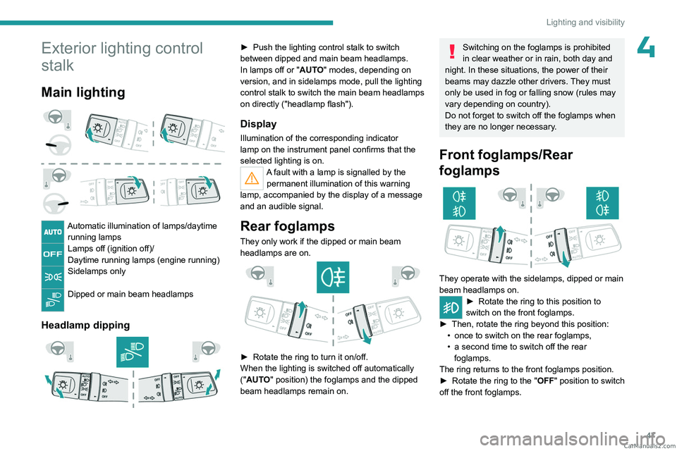
Automatic illumination of lamps/daytime running lamps
Lamps off (ignition off)/
Daytime running lamps (engine running)
Sidelamps only
Dipped or main beam headlamps
Headlamp dipping
► Push the lighting control stalk to switch
between dipped and main beam headlamps.
In lamps off or "
AUTO" modes, depending on
version, and in sidelamps mode, pull the lighting
control stalk to switch the main beam headlamps
on directly ("headlamp flash").
Display
Illumination of the corresponding indicator
lamp on the instrument panel confirms that the
selected lighting is on.
A fault with a lamp is signalled by the permanent illumination of this warning
lamp, accompanied by the display of a message
and an audible signal.
Rear foglamps
They only work if the dipped or main beam headlamps are on.
► Rotate the ring to turn it on/off.
When the lighting is switched off automatically
("
AUTO" position) the foglamps and the dipped
beam headlamps remain on.
Switching on the foglamps is prohibited
in clear weather or in rain, both day and
night. In these situations, the power of their
beams may dazzle other drivers. They must
only be used in fog or falling snow (rules may
vary depending on country).
Do not forget to switch off the foglamps when
they are no longer necessary.
Front foglamps/Rear
foglamps
They operate with the sidelamps, dipped or main
beam headlamps on.
► Rotate the ring to this position to
switch on the front foglamps.
►
Then, rotate the ring beyond this position:
•
once to switch on the rear foglamps,
•
a second time to switch off the rear
foglamps.
The ring returns to the front foglamps position.
►
Rotate the ring to the "
OFF" position to switch
off the front foglamps. CarM an uals 2 .c o m
Page 67 of 164
65
Safety
5An incorrectly installed child seat in a vehicle compromises the child's safety in
the event of an accident.
Strictly observe the fitting instructions
provided in the user guide supplied with the
child seat.
Manual child lock
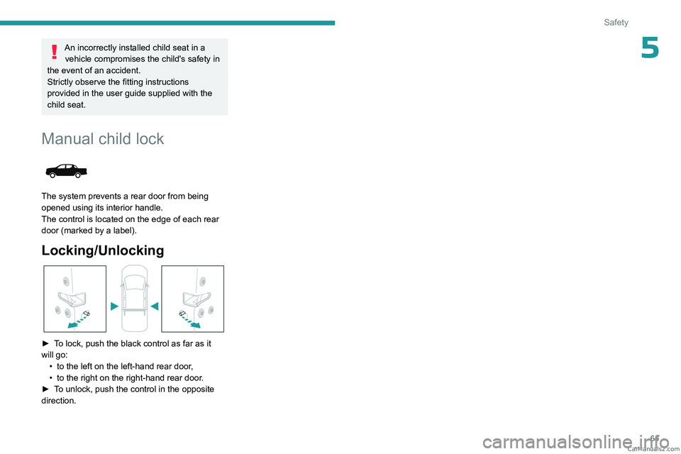
The system prevents a rear door from being
opened using its interior handle.
The control is located on the edge of each rear
door (marked by a label).
Locking/Unlocking
► To lock, push the black control as far as it
will go: •
to the left on the left-hand rear door
,
•
to the right on the right-hand rear door
.
►
T
o unlock, push the control in the opposite
direction. CarM an uals 2 .c o m